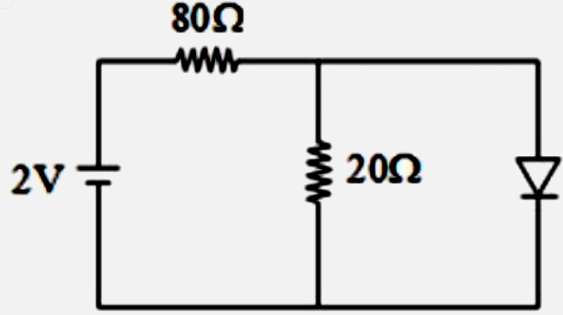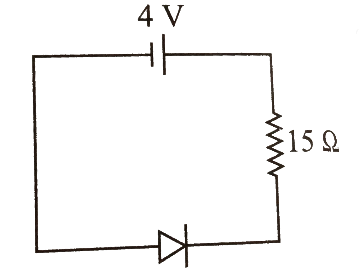
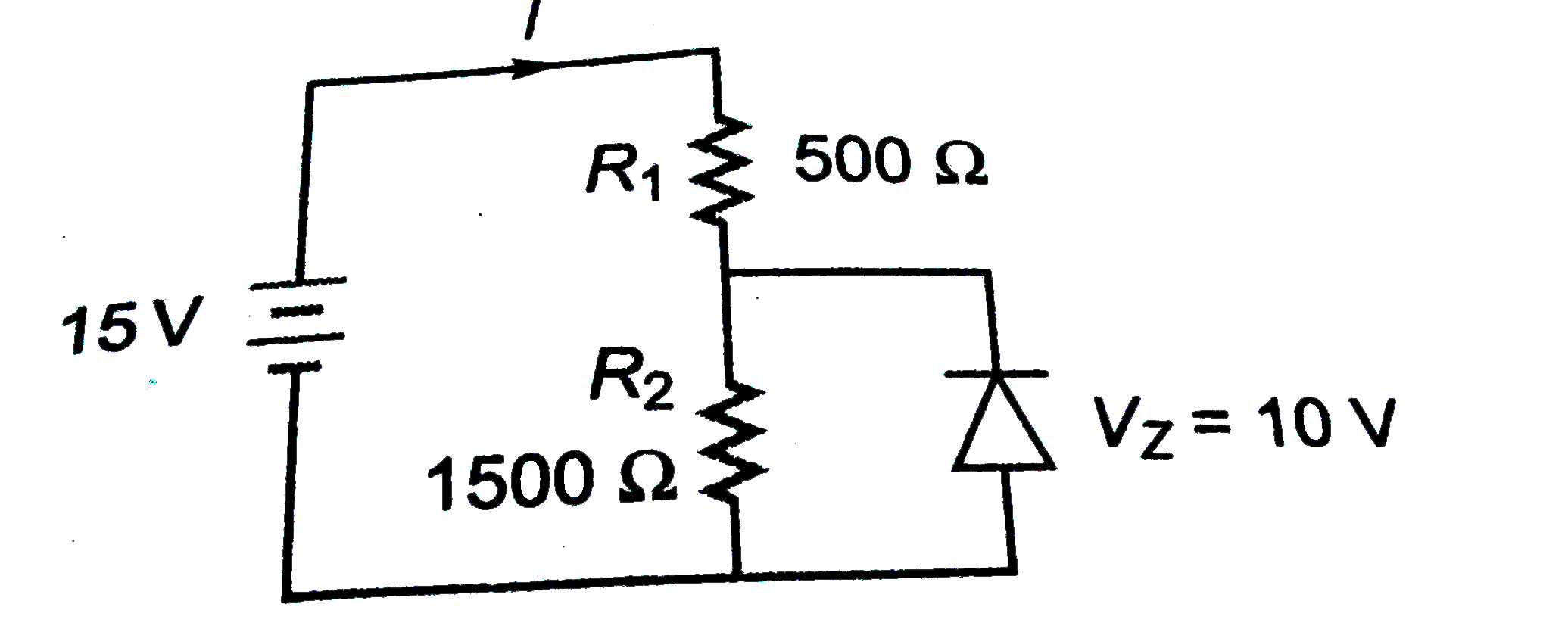
In the circuit shown if current for the diode is , the potential difference across the diode is
A
2 V
B
4.5V
C
4 V
D
2.5 V
Video Solution
Text Solution
The correct Answer is:C
Since the diode is reversed biased, only drift current exists in circuit which is
Potential drop across resistor
Potential difference across the diode = 4 -0.0003 = 3.99 = 4V.
|
Topper's Solved these Questions
- SEMICONDUCTOR ELECTRONICS : MATERIALS , DEVICES AND SIMPLE CIRCUITS BOOK - NCERT FINGERTIPSCHAPTER - SEMICONDUCTOR ELECTRONICS : MATERIALS , DEVICES AND SIMPLE CIRCUITS EXERCISE - Application Of Junction Diode As A Rectifier
5 Videos
- SEMICONDUCTOR ELECTRONICS : MATERIALS , DEVICES AND SIMPLE CIRCUITS BOOK - NCERT FINGERTIPSCHAPTER - SEMICONDUCTOR ELECTRONICS : MATERIALS , DEVICES AND SIMPLE CIRCUITS EXERCISE - Special Purpose P-N Junction Diode
8 Videos
- SEMICONDUCTOR ELECTRONICS : MATERIALS , DEVICES AND SIMPLE CIRCUITS BOOK - NCERT FINGERTIPSCHAPTER - SEMICONDUCTOR ELECTRONICS : MATERIALS , DEVICES AND SIMPLE CIRCUITS EXERCISE - P-N Junction
6 Videos
- RAY OPTICS AND OPTICAL INSTRUMENTSBOOK - NCERT FINGERTIPSCHAPTER - RAY OPTICS AND OPTICAL INSTRUMENTSEXERCISE - Assertion And Reason
15 Videos
- WAVE OPTICSBOOK - NCERT FINGERTIPSCHAPTER - WAVE OPTICSEXERCISE - Assertion And Reason
15 Videos
Similar Questions
Knowledge Check

In the circuit shown if current for the diode is 20μA, the potential difference across the diode isA2VB4.5VC4VD2.5VIn the circuit shown in figure , the diode is ideal The potential difference between A and B is
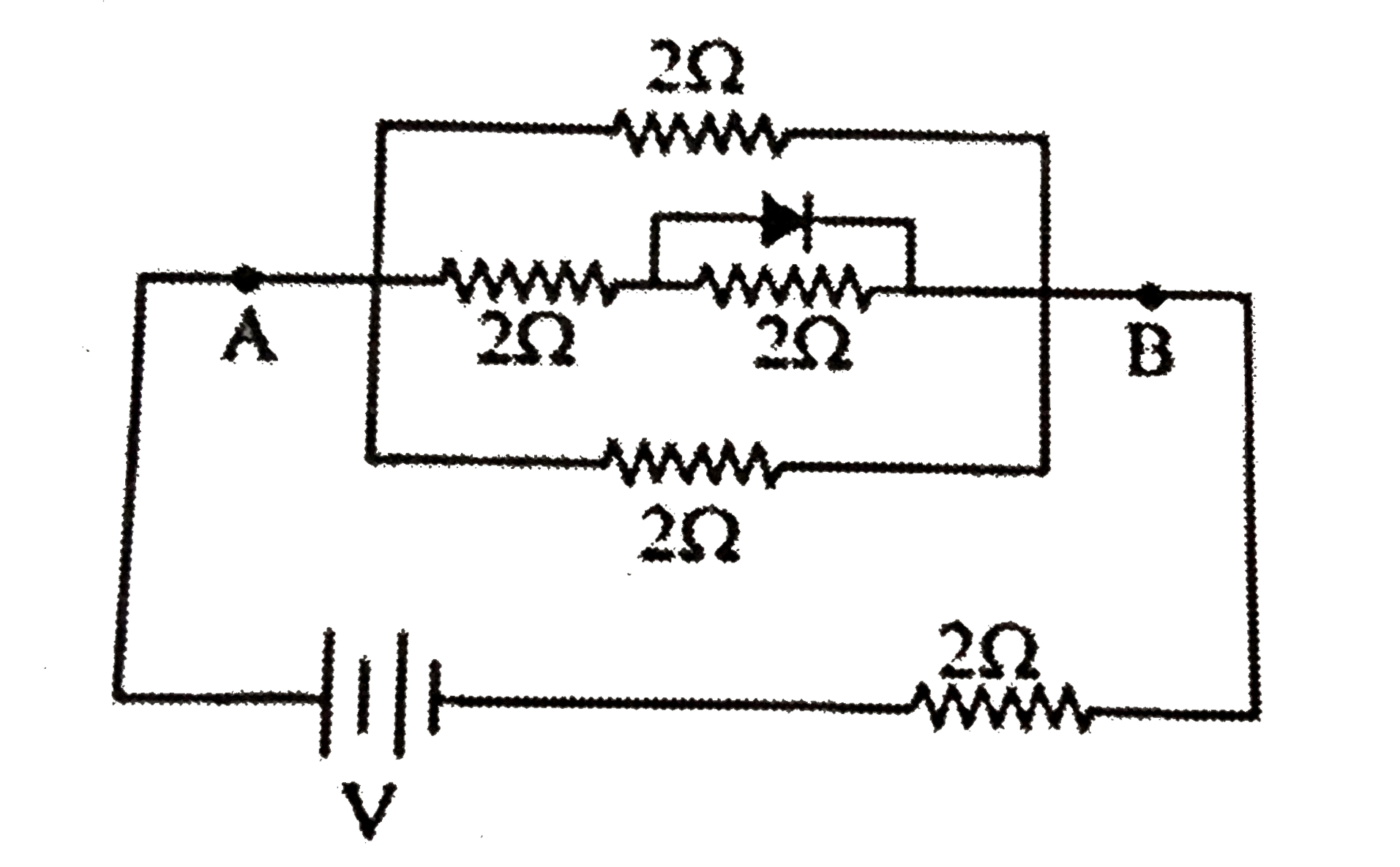 AV/4BVCzeroDV/2
In the diode circuit shown in figure,
 AD1andD2 are reverse biasedBD1andD2 are forward biasedCD1 is forward biased and D2 is reverse biased.DD1 is reverse biased and D2 is forward biased.
In the circuit given the current through the Zener diode is
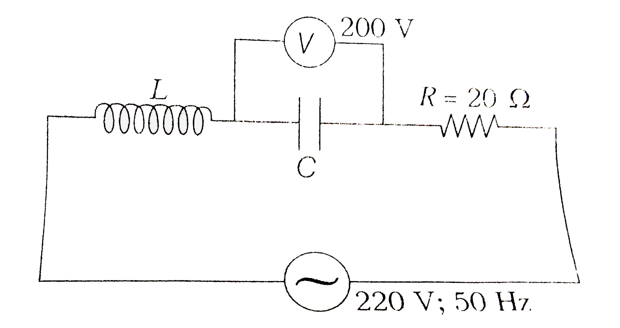
View SolutionIn the circuit shown, rms circuit is 11 A . The potential difference across the inductor is
View SolutionIn the circuit, Fig.he current through the zener diode is
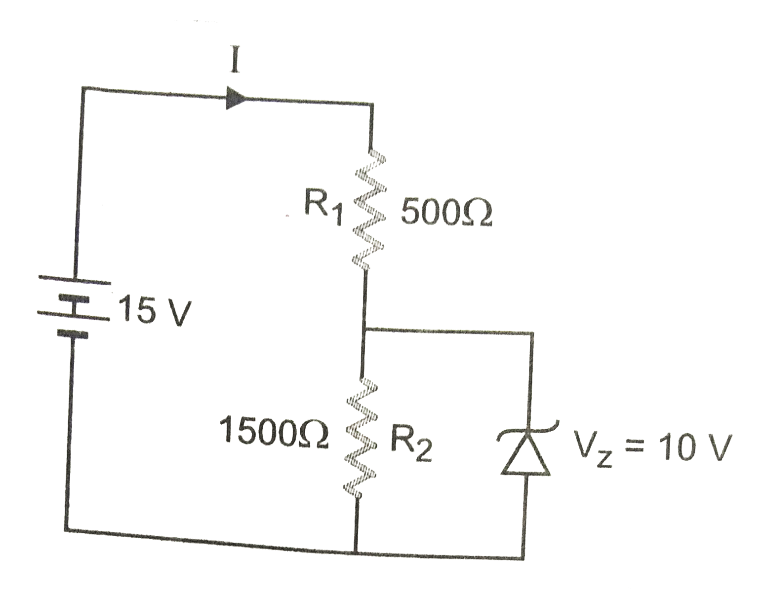
View SolutionIn the circuit given, the current through the Zener diode is

View SolutionIn the shown circuit, what is the potential difference across A and B
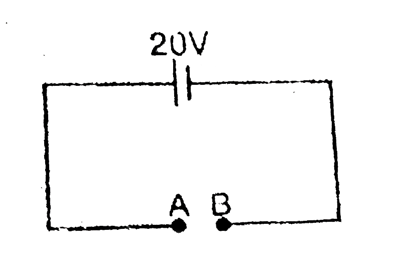
View Solution

