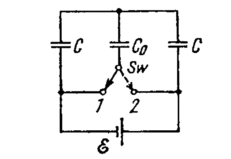
In the circuit shown in Fig. 12.3, when the switch is moved to ‘ON’ position
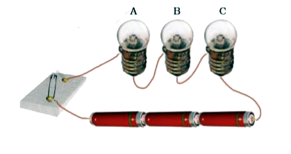
the bulb A will glow first.
the bulb B will glow first.
the bulb C will glow first
all bulbs will glow together
The correct Answer is:D
Step by step video & image solution for In the circuit shown in Fig. 12.3, when the switch is moved to ‘ON’ position by Physics experts to help you in doubts & scoring excellent marks in Class 6 exams.
Updated on:21/07/2023Topper's Solved these Questions
- ELECTRICITY AND CIRCUITSBOOK - NCERT EXEMPLARCHAPTER - ELECTRICITY AND CIRCUITSEXERCISE - VERY SHORT ANSWER QUESTIONS
2 Videos
- ELECTRICITY AND CIRCUITSBOOK - NCERT EXEMPLARCHAPTER - ELECTRICITY AND CIRCUITSEXERCISE - SHORT ANSWER QUESTIONS
10 Videos
- FUN WITH MAGNETSBOOK - NCERT EXEMPLARCHAPTER - FUN WITH MAGNETSEXERCISE - LONG ANSWER QUESTIONS
7 Videos
Similar Questions
Knowledge Check
In the circuit shown in Fig. 7.45,
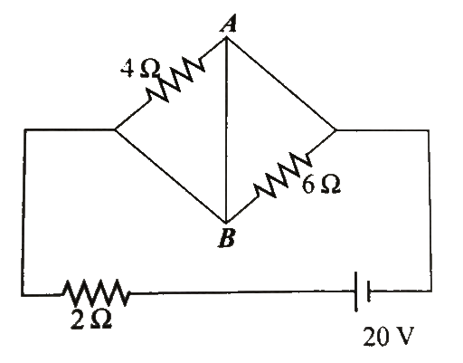 APower supplied by the battery is 200WBcurrent flowing in the circuit is 5ACPotential difference across the 4Ω resistance is equal to the potential difference across the 6Ω resistanceDcurrent in wire AB is zero
In the circuit shown in the following figure, the switch is moved to position 1 at t = 0. Which of the following most closely represents the current I as a function of time?
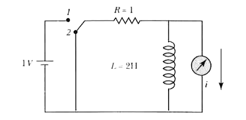 A
A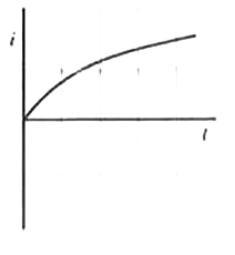 B
B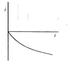 C
C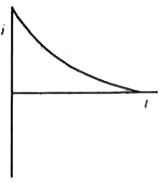 D
D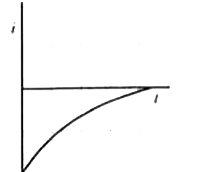
In the circuit shown in fig. when the switch is closed, the capacitor charges with a time constant
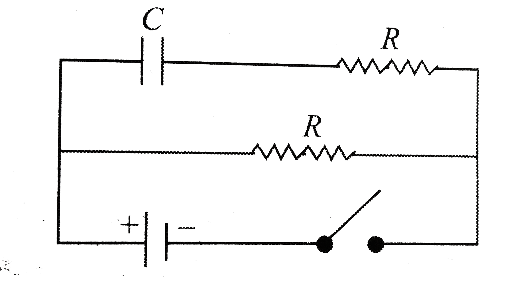 ARCB2 RCC12RCDRC log2
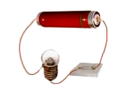
An electric bulb is connected to a cell through a switch as shown in Fig. 12.7. When the switch is brought in ‘ON’ position, the bulb does not glow. What could be the possible reason/s for it? Mention any two of them.
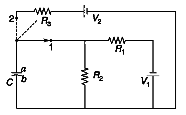
View SolutionIn the circuit shown in fig. the switch is kept closed in position 1 for a long time. At time t=0 the switch is moved to position 2. Write the dependence of voltage (VC) across the capacitor as a function of time (t). Take VC to be positive when plate a is positive.
Given: R1=20Ω,R2=60Ω,R3=400kΩ,V1=40V,V2=90VandC=0.5μF.
View Solution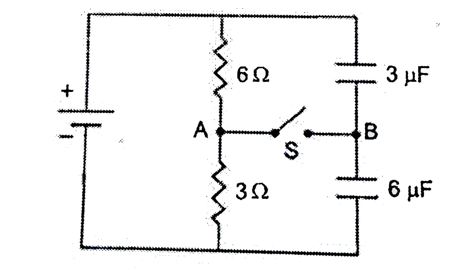
In the circuit shown above, when then switch S is closed,
View SolutionIn the circuit shows in Fig the switch is closed at t=0.

View SolutionIn the circuit shown in figure-3.348 when the switch is closed, the initial current through the 1Ω resistor just after closing the switch is
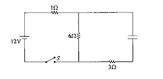
View Solution


