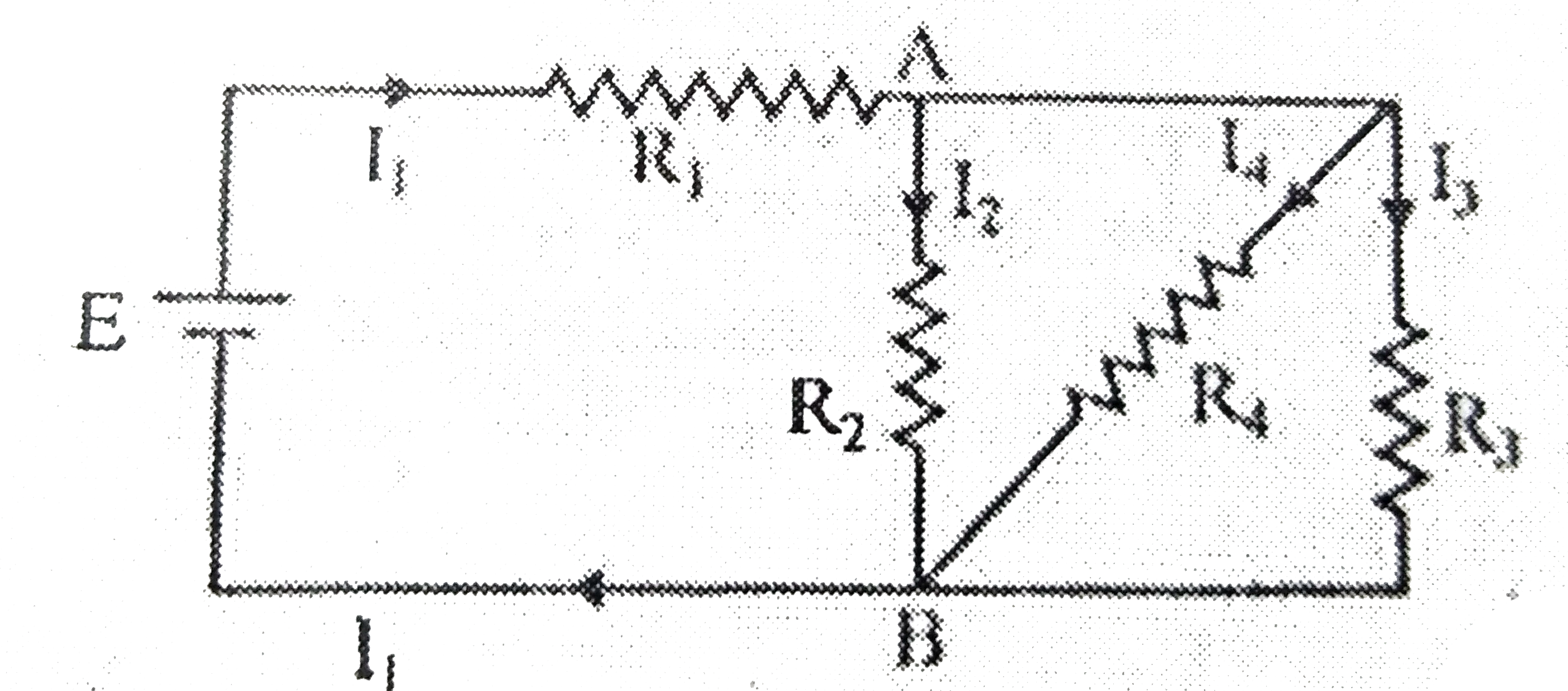
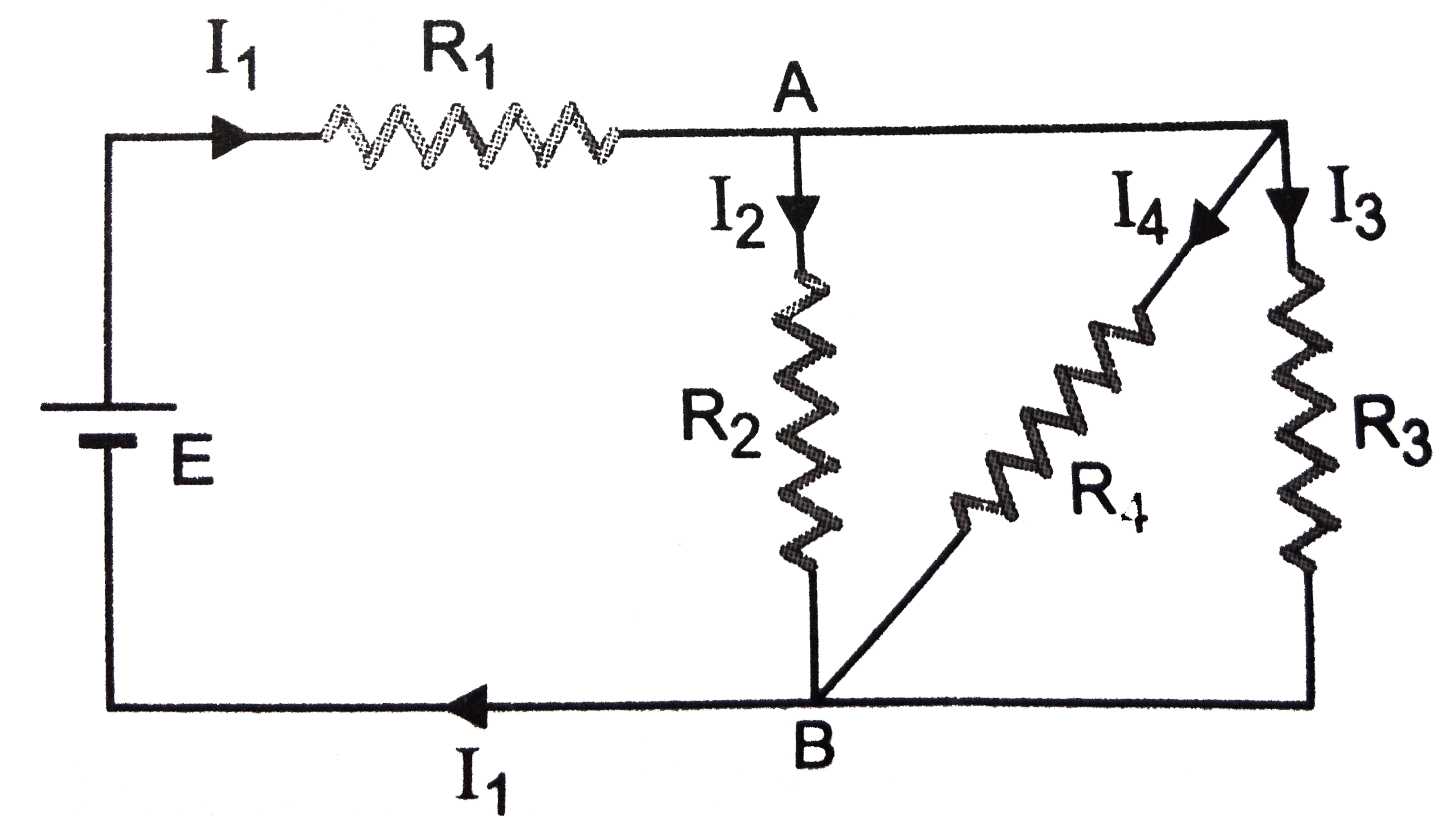
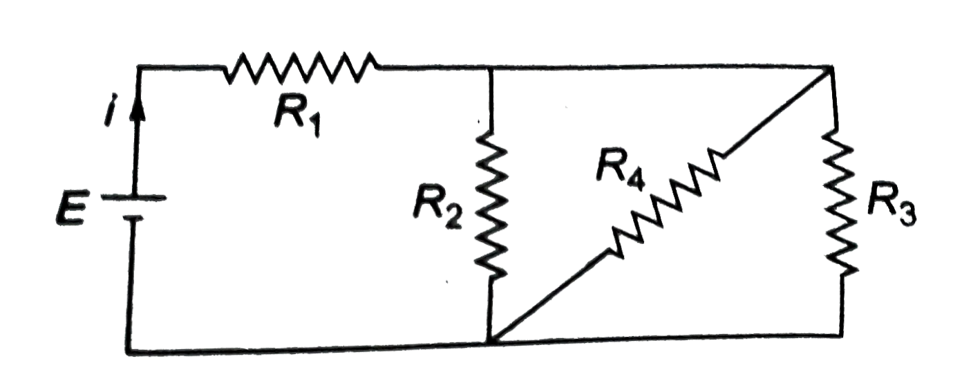
In the circuit shown in Fig. 4.19. R1=100Ω,R2=R3=50Ω,R4=75Ω and E=4.75 V. Work out the equivalent resistance of the circuit and the current in each resistor.
Step by step video & image solution for In the circuit shown in Fig. 4.19. R_(1)=100 Omega, R_(2)=R_(3)=50 Omega, R_(4)=75 Omega and E=4.75 V. Work out the equivalent resistance of the circuit and the current in each resistor. by Physics experts to help you in doubts & scoring excellent marks in Class 12 exams.
Updated on:21/07/2023Topper's Solved these Questions
- CURRENT ELECTRICITYBOOK - SL ARORACHAPTER - CURRENT ELECTRICITYEXERCISE - Problems From Competitive
18 Videos
- CURRENT ELECTRICITYBOOK - SL ARORACHAPTER - CURRENT ELECTRICITYEXERCISE - Problems For Self
101 Videos
- CHEMICAL EFFECT OF CURRENTBOOK - SL ARORACHAPTER - CHEMICAL EFFECT OF CURRENTEXERCISE - TYPE-B
5 Videos
- ELECTRIC POTENTIAL AND ELECTRIC FLUXBOOK - SL ARORACHAPTER - ELECTRIC POTENTIAL AND ELECTRIC FLUXEXERCISE - Problems for self practive
61 Videos
Similar Questions
Knowledge Check
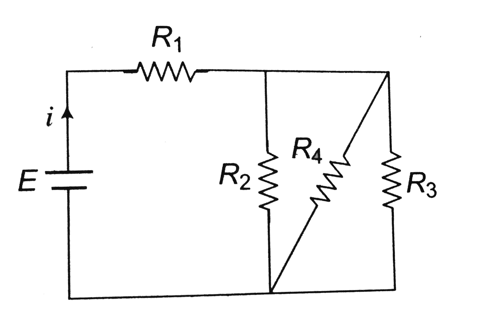
In the circuit given E=6.0V,R1=100ohms,R2=R3=50ohms,R4=75ohms. The equivalent resistance of the circuit, in ohms, is
 A11.875B26.31C118.75DNone of these
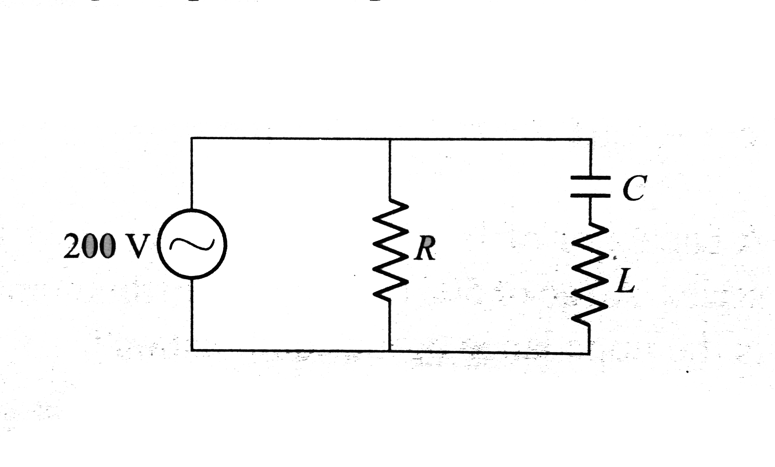
In the circuit shown in fig. XC=100Ω,(XL)=200ΩandR=100Ω. The effective current through the source is
 A2AB2√2AC0.5AD√0.4A
In the circuit shown below E1=4.0V,R1=2Ω,E2=6.0V,R2=4Ω and R3=2Ω. The current I1 is
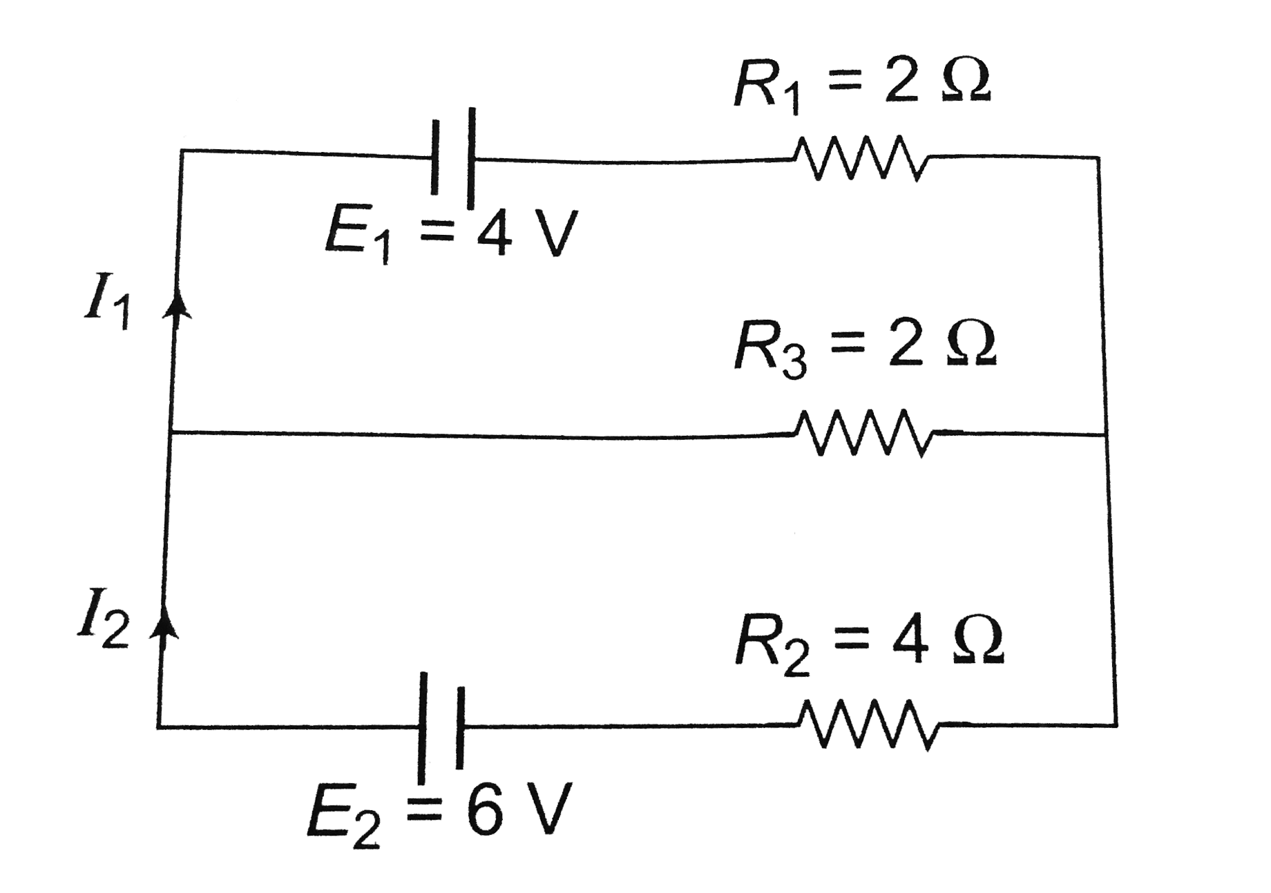 A1.6AB1.8AC1.25AD1.0A
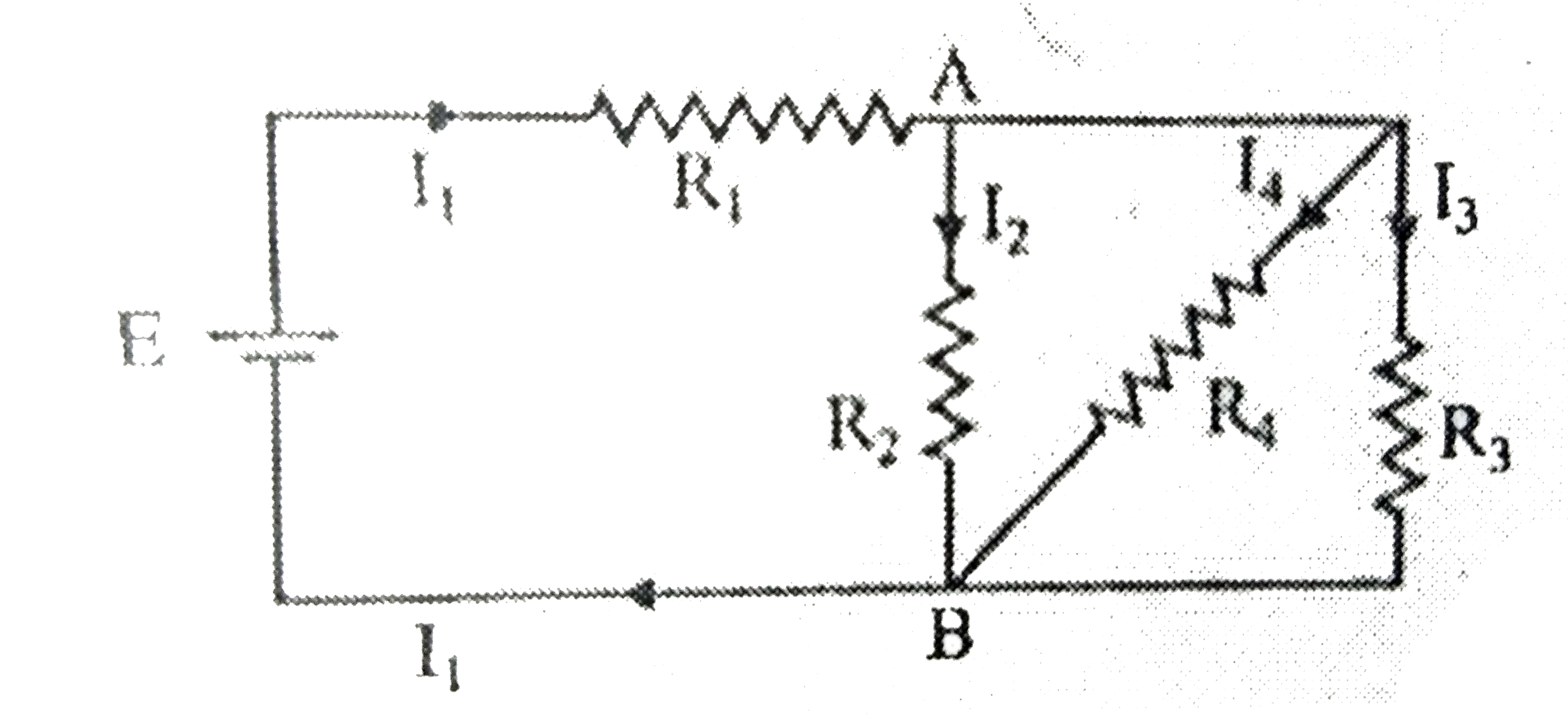
In the circuit shown , R1=4Ω,R2=R3=15Ω,R4=30Ω and ε=10V . Calculate the equivalent resistance of the circuit and the current in each resistor.
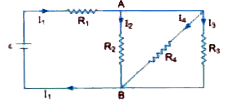
View SolutionIn the circuit shown, R1=4Ω,R2=R3=15Ω,R4=30ΩandE=10V. Caculate the equivalent resistance of te circuit and the current in each resistor.
View SolutionIn the circuit given E = 6.0 volt, R1=100Ω,R2=R3=50Ω and R4=75Ω. The equivalent resistance of the circuit, in ohms is
View SolutionFind a potentail difference φ1−φ2 between points 1 and 2 of the circuit shown in Fig if R11=10Ω,R2=20Ω,E1=5.0V, and E2=2.0V. The internal resisances of the current sources are negligible.

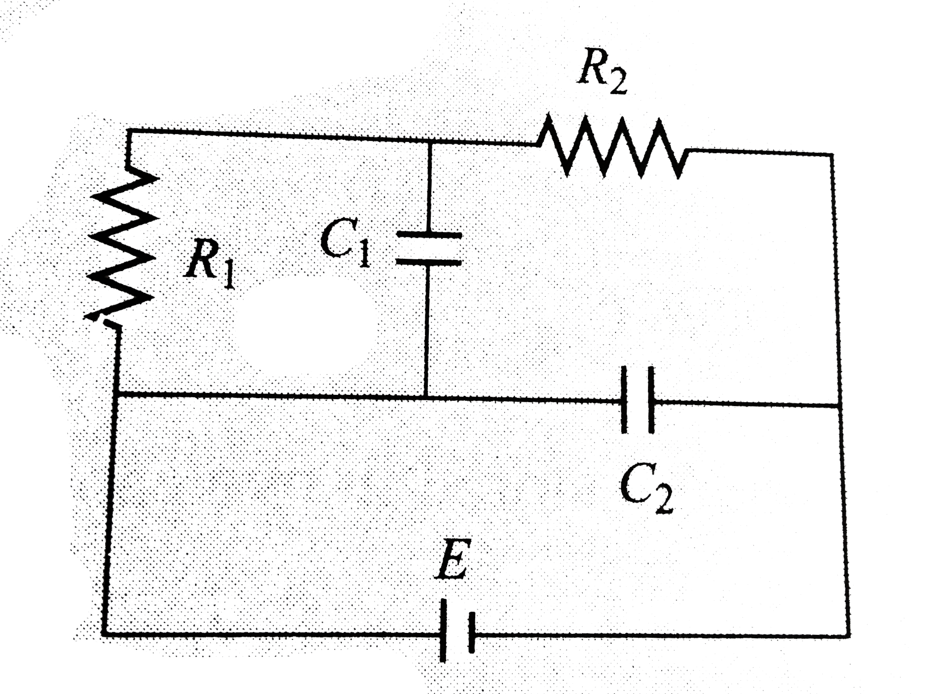
View SolutionIn the circuit shown in fig. R1=10Ω,R2=Ω,C1=1μF,C2=2μF, and E =6V. Calculate the charge on each capactor in the stedy state.
View Solution

