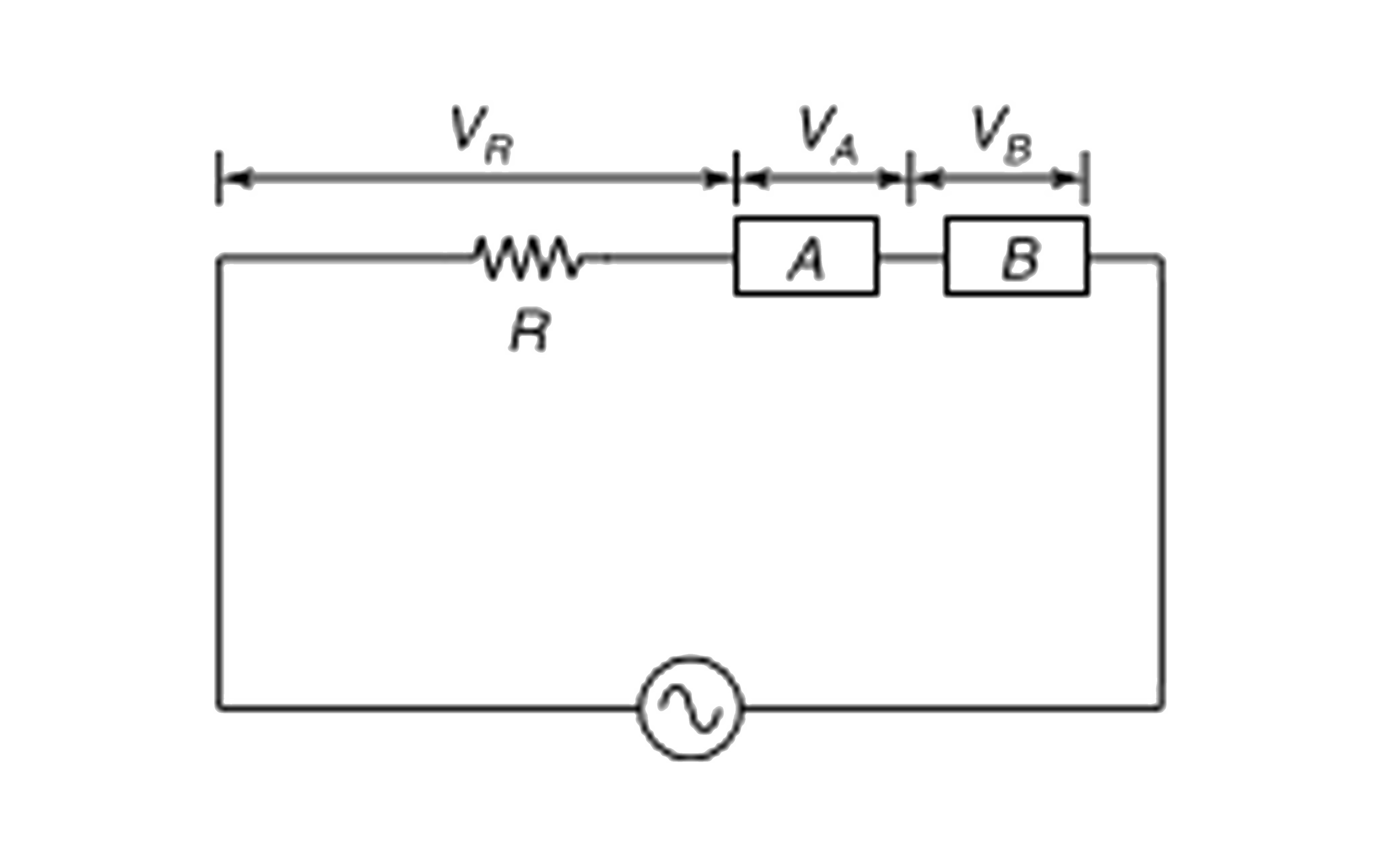
In the circuit shown in the Figure, the voltage across resistance R, box A and box B are represented as
vR=vsin(ωt),vA=√2Vsin(ωt+π4)and
vB=vsin(ωt+π2)Find the phase difference between current and the applied voltage.

The correct Answer is:45∘
Step by step video, text & image solution for In the circuit shown in the Figure, the voltage across resistance R, box A and box B are represented as v_(R)=vsin(omegat),v_(A)=sqrt(2)Vsin(omegat+(pi)/(4))and v_(B)=vsin(omegat+(pi)/(2))Find the phase difference between current and the applied voltage. by Physics experts to help you in doubts & scoring excellent marks in Class 12 exams.
Topper's Solved these Questions
Similar Questions
Knowledge Check
- Question 1 - Select One
Two simple harmonic motions A and B are given respectively by the following equations.
y1=asin[ωt+π6]
y2=asin[ωt+3π6]
Phase difference between the waves isAπ2Bπ6Cπ3DZero - Question 2 - Select One
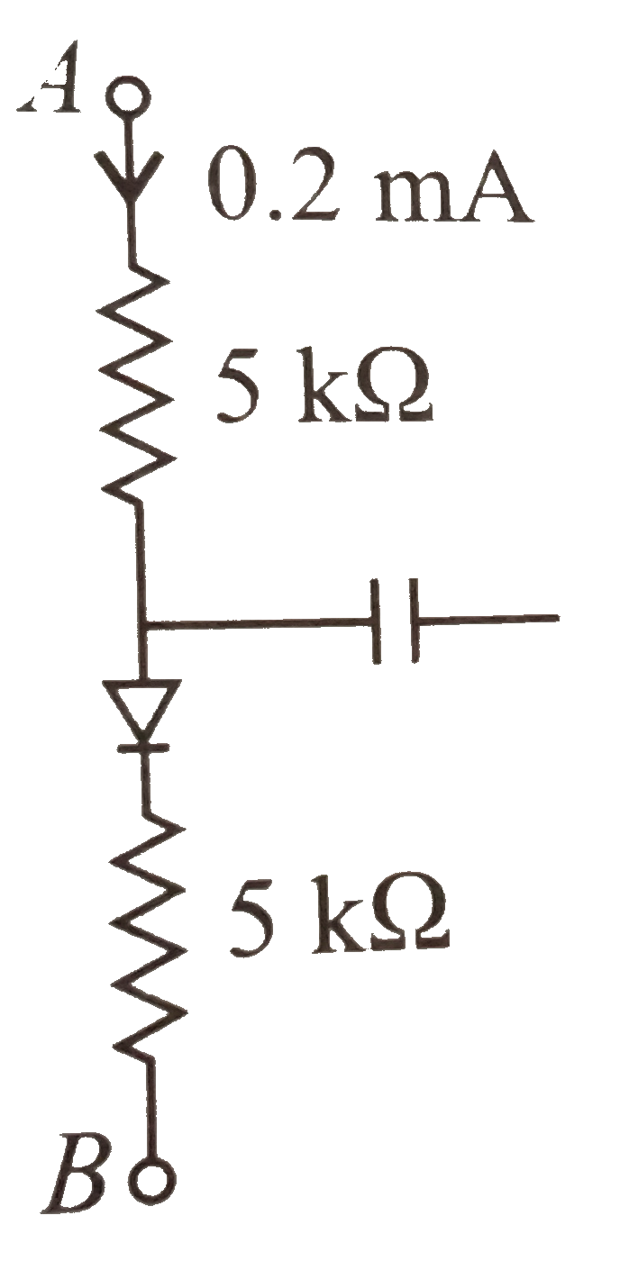
In the circuit shown in figure, if the A diode forward voltage drop is 0.3 V, the voltage difference between A and B is
 A1.3 VB2.3 VC0D0.5 V
 - Question 3 - Select One
In the circuit shown in figure, if the diode forward voltage drop is 0.3 V, then the voltage difference between A to B is,
 A1.3 VB2.3 VCzeroD0.5V
The instantaneous voltages at three terminals marked X, Y and Z are given by
VX=V0sinωt,VY=V0sin(ωt=2π3)andVz=V0sin(ωt=4π3)
An ideal voltmeter is configured to read runs value of the potential difference between its terminals. is connected between points X and Y and then between Y and Z. The reading the voltmeter will beView SolutionTwo SHMs are respectively represented by y1=asin(ωt−kx)andy2=bcos(ωt−kx). The phase difference between the two is
View SolutionThe instantaneous voltages at three terminals marked X, Y and Z are given by [
Vx=V0sinωt,
VY=V0sin(ωt+2π3) and
VZ=V0sin(ωt+4π3)
An ideal voltmeter is configured to read rms value of the potential difference between its terminals. It is connected between points X and Y and then between Y and Z. The reading(s) of the voltmeter will beView SolutionWhat is the phase difference between two simple harmonic motions represented by x1=Asin(ωt+π6) and x2=Acosωt?
View SolutionIn the circuit given below, V(t) is the sinusoidal voltage source, voltage drop VAB(t) across the resistance R is
 View Solution

