In the figure shown, the currents through the series resistance and load resistance are respectively
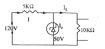
9mA, 14mA
14mA, 5mA
1mA, 14mA
1mA, 6mA
The correct Answer is:B
Step by step video & image solution for In the figure shown, the currents through the series resistance and load resistance are respectively by Physics experts to help you in doubts & scoring excellent marks in Class 12 exams.
Updated on:21/07/2023Topper's Solved these Questions
- SEMICONDUCTOR DEVICESBOOK - AAKASH SERIESCHAPTER - SEMICONDUCTOR DEVICESEXERCISE - EXERCISE - III
3 Videos
- SEMICONDUCTOR DEVICESBOOK - AAKASH SERIESCHAPTER - SEMICONDUCTOR DEVICESEXERCISE - EXERCISE - IB
7 Videos
- RAY OPTICSBOOK - AAKASH SERIESCHAPTER - RAY OPTICSEXERCISE - PROBLEMS ( LEVEL-II)
60 Videos
- UNITS AND MEASUREMENTBOOK - AAKASH SERIESCHAPTER - UNITS AND MEASUREMENTEXERCISE - PRACTICE EXERCISE
45 Videos
Similar Questions
A zener diode of voltage VZ(=6 volt) is used to maintain a constant voltage across a load resistance RL(=1000Ω) by using a series resistance RS(+100Ω). If the emf or source is E(=9V), clculate the value of current through series resistance, zener diode and load resistance. What is the power being dissipated in zener diode.
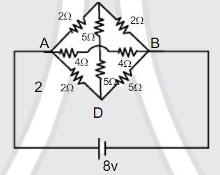
View SolutionFind current through 4ohm resistance
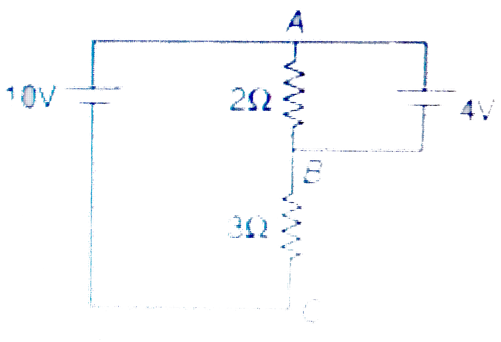
View SolutionIn the situation shown, the currents through 3Ω and 2Ωresistances are in the ratio.

View SolutionIn the circuit, the current flowing through 10Ω resistance is
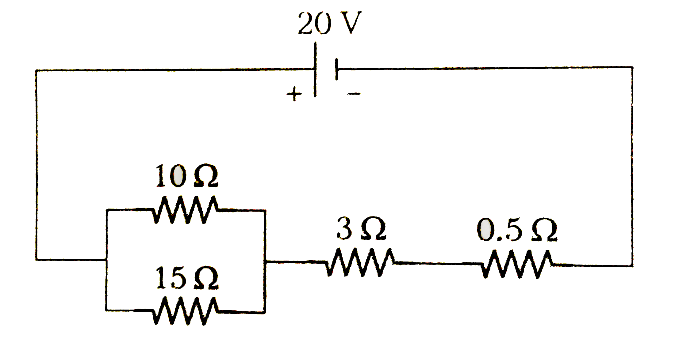
View SolutionCurrent passing through 3Ω resistance is
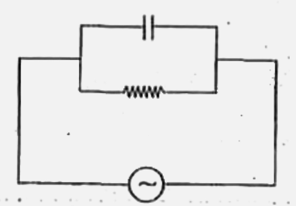
View SolutionIn the attemating current circuit shown in the figure, the currents through resistor and capacitor are 3 A and 4 A respectively. The current drawn from generator is
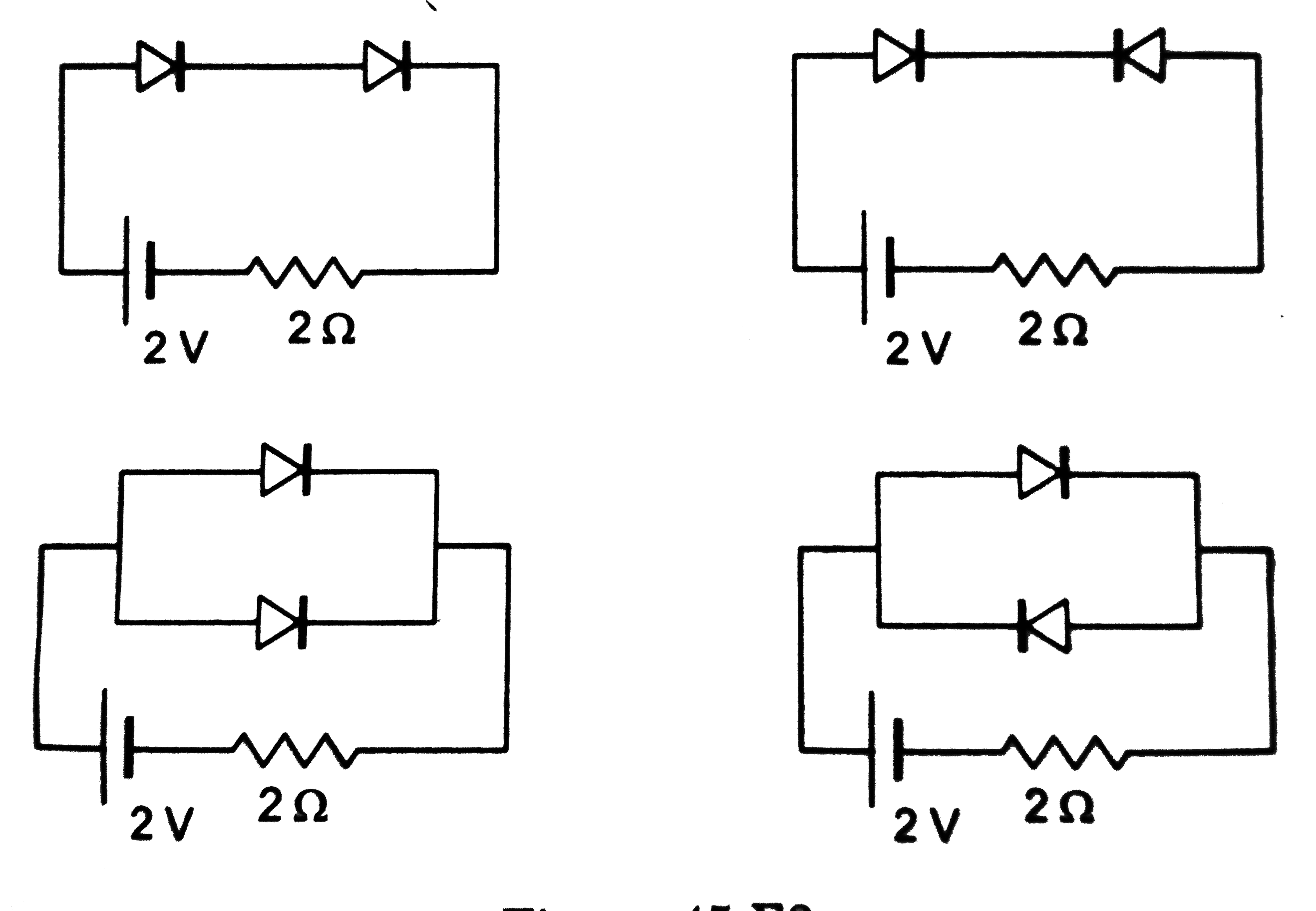
View SolutionFind the current through the resistance in the circuits shown in figure
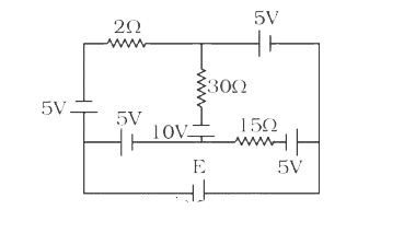
View SolutionIn the circuit shown, current through the resistance2Ω isi1 and current through the resistance30Ω is i2. The ratio i1i2 is equal to
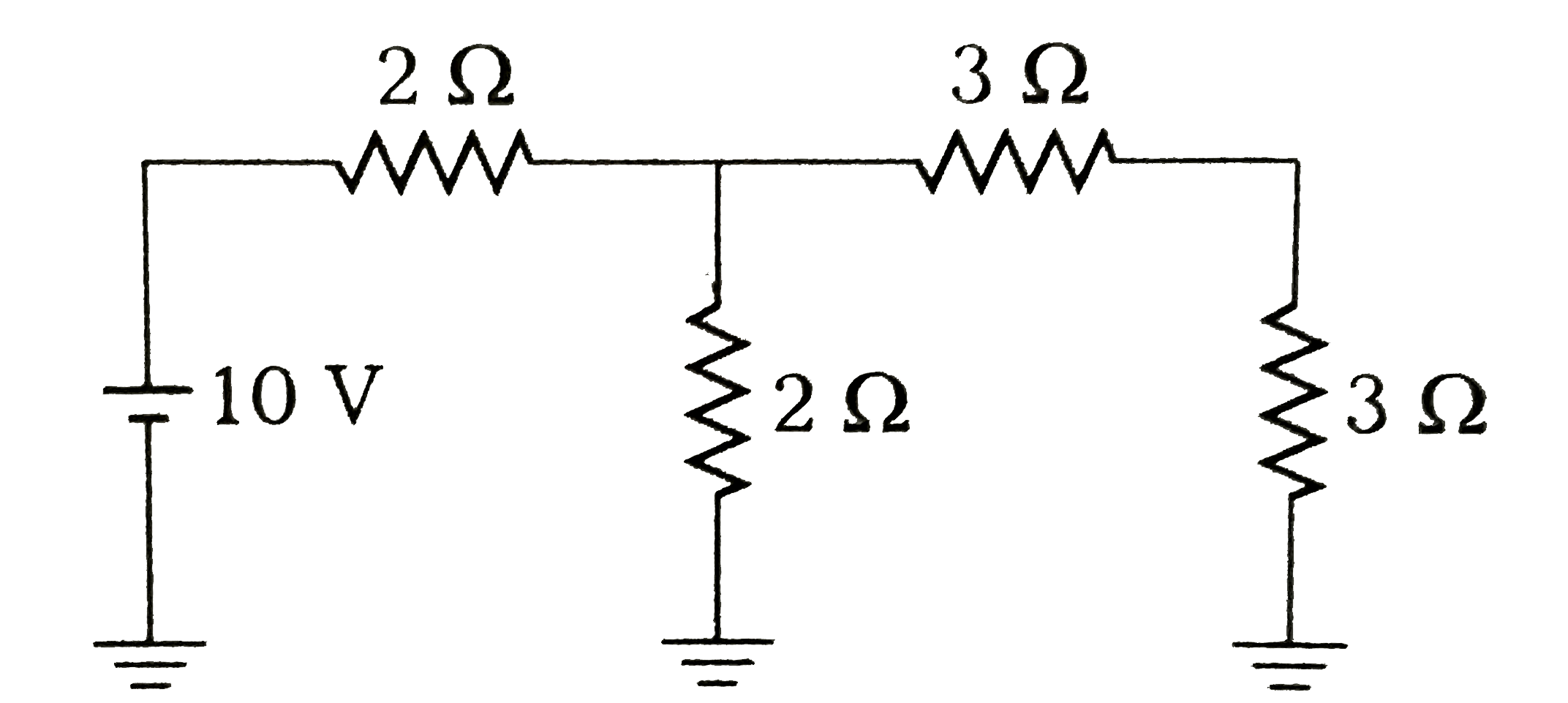
View SolutionIn the circuit shown, the current in 3Ω resistance is
View SolutionIn the given circuit, the current through the resistance R is __________ A.
View Solution
