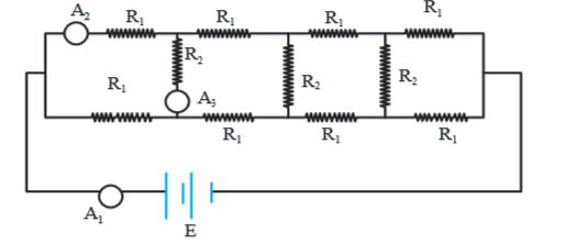
In the given circuit, R1 = 10Ω R2=6Ω and E = 10V, then correct statement is
The errors of measurement of two students are the same
Errors of measurement do depend on the accuracy with which R2andR1 can be measured
If the student uses large values of R2andR1 the currents through the arms will be feeble. This will make determination of null point accurately more difficult.
Whatstone bridge is a very accurate instrument and has no errors of measurement.
The correct Answer is:B, C
Given, for first student, R2=10Ω,R1=5Ω,R3=5Ω
For second student, R1=500Ω,R3=5Ω.
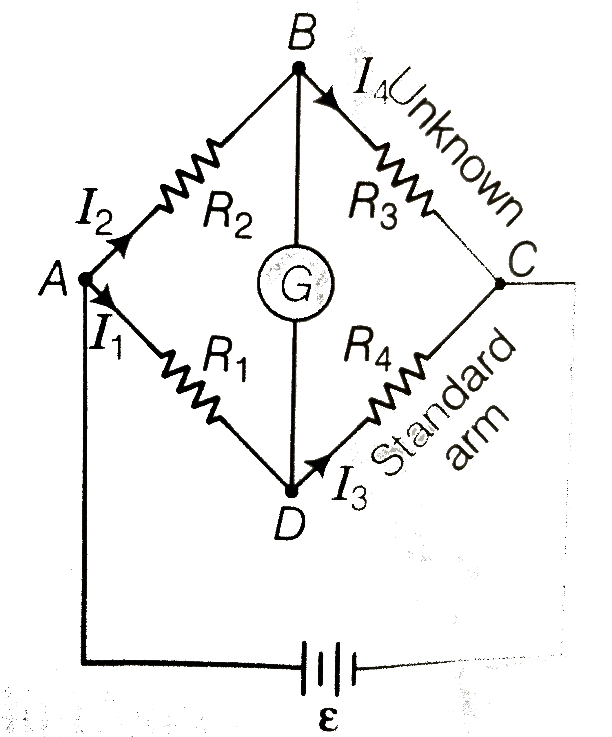
Now, according to whatstone bridge rule,
R2R=R1R3⇒R=R3×R2R1
Now putting all the values in Eq. (i) we get R=10Ω for both students. Thus, we can analyse that the wheatstone bridge is mot sensitive and accurate if resistances are of same value.
Thus, the errors of measurement of the two students depend on the accuracy and sensitivity of the bridge, which inturn depends on the accuracy with which R2andR1 can be measured. when R2andR1 are larger, the currents through the arms of bridge is very weak. this can make the determination of null point accurately more difficult.
Topper's Solved these Questions
- BOOK - NCERT EXEMPLAR ENGLISHCHAPTER - CURRENT ELECTRICITYEXERCISE - Very Short Answer Type Question.20videos
CURRENT ELECTRICITY
- BOOK - NCERT EXEMPLAR ENGLISHCHAPTER - CURRENT ELECTRICITYEXERCISE - Very Short Answer Type Question.20videos
CURRENT ELECTRICITY
- BOOK - NCERT EXEMPLAR ENGLISHCHAPTER - COMMUNICATION SYSTEMEXERCISE - LONG ANSWER TYPE QUESTIONS5videos
COMMUNICATION SYSTEM
- BOOK - NCERT EXEMPLAR ENGLISHCHAPTER - DUAL NATURE OF RADIATION AND MATTEREXERCISE - LONG ANSWER TYPE QUESTION5videos
DUAL NATURE OF RADIATION AND MATTER
Similar Questions
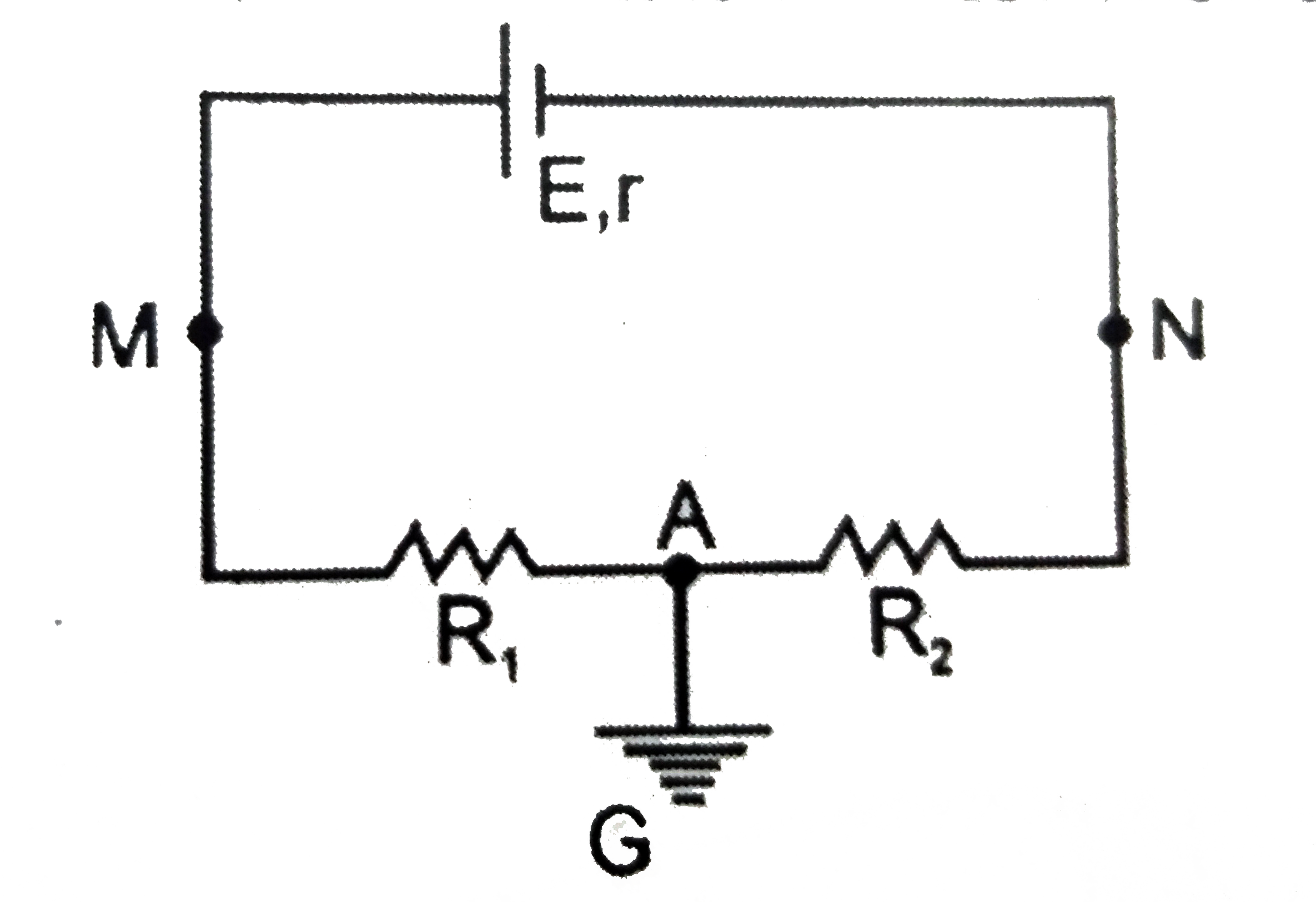
In the given figure, E=12V, R1=3Ω,R2=2Ω and r=1Ω. The choose the correct option/s
 View Solution
In an AC series circuit, R=10Ω,XL=20Ω and XC=10Ω.Then, choose the correct options
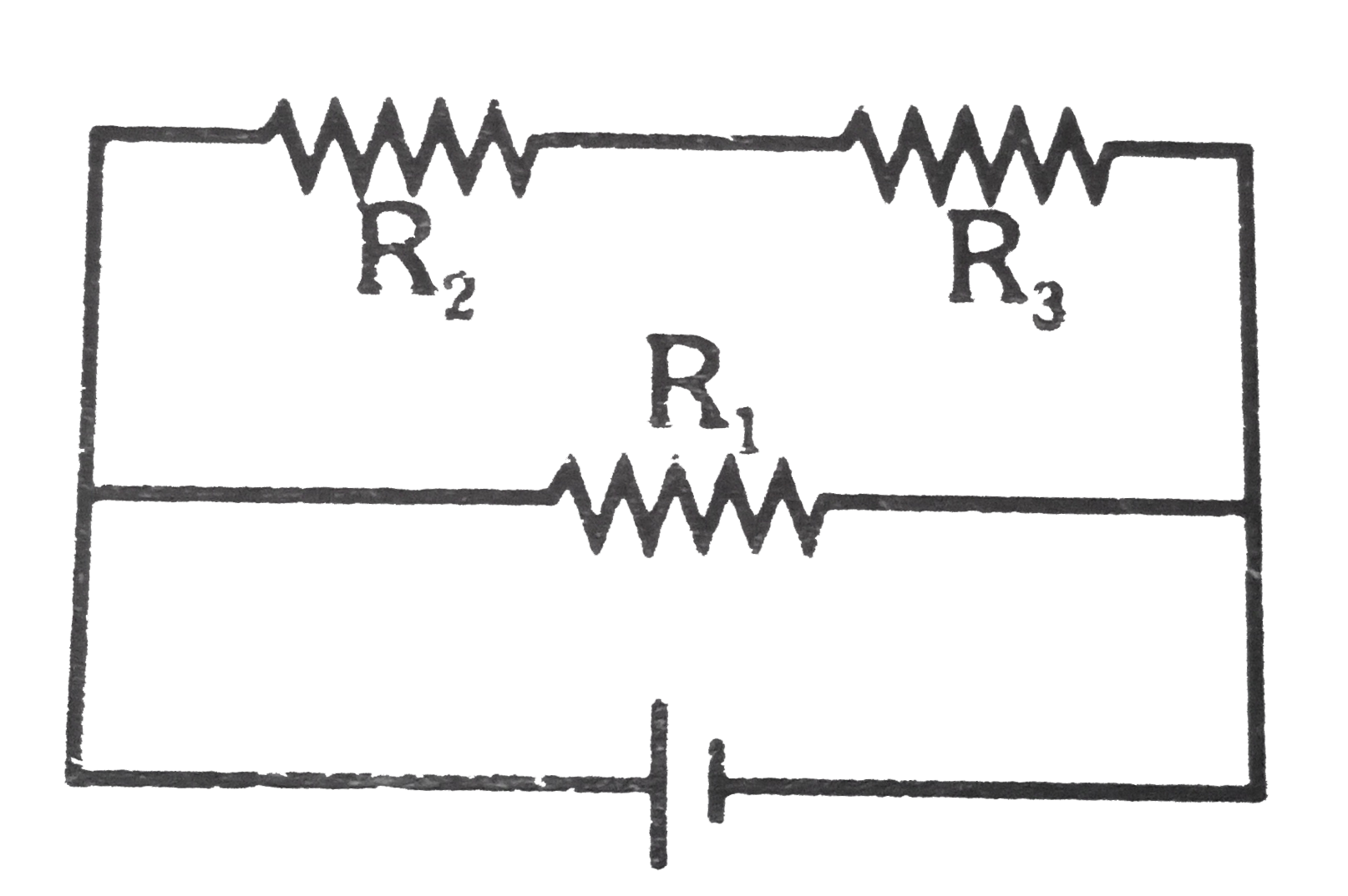
View SolutionIn given circuit R1=5Ω,R2=3Ω=7Ω and supply voltage is 10V. Calculate power dissipated in R1 and R3.
 View Solution
In an L-C-R series circuit R = 10Ω,XL=8Ωand XC=6Ωthe total impedance of the circuit is -
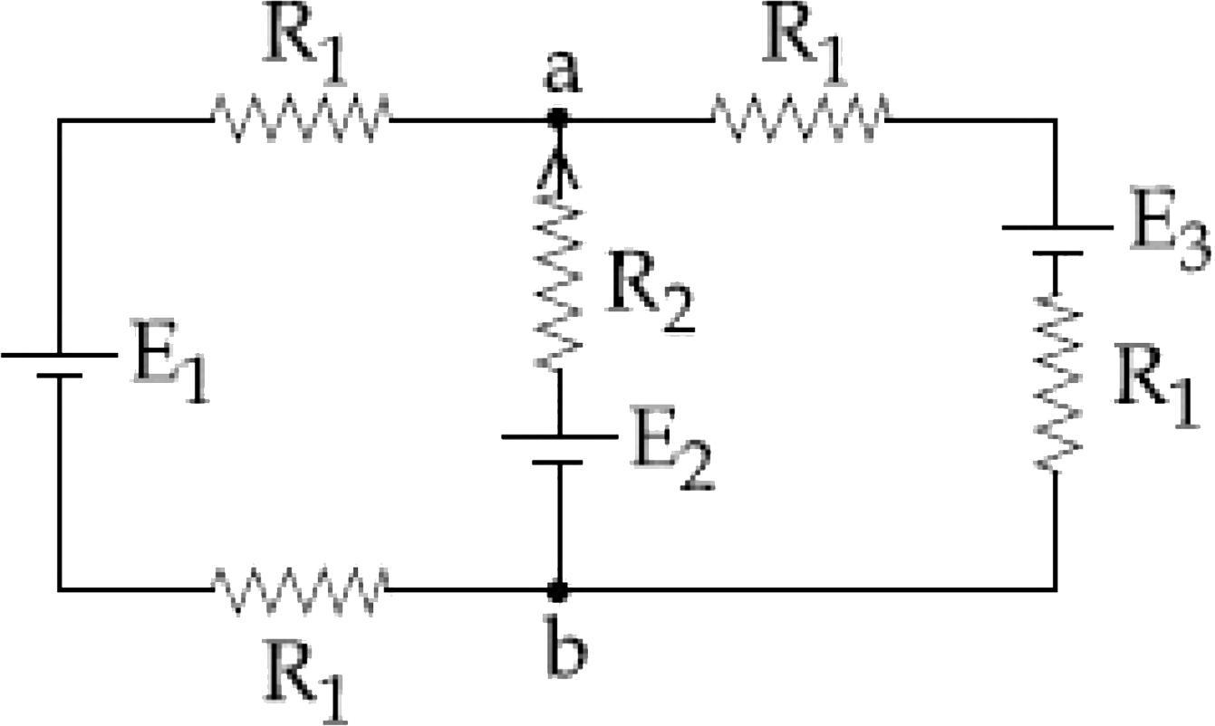
View SolutionFor the circuit shown, with R1=1.0Ω,R2=2.0Ω,E1=2V and E2=E3=4V, the potential difference between the points 'a' and 'b' is approximately (in V):
 View Solution
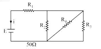
In the given circuit, E=8V,R1=1Ω,R2=R3=R4=5Ω.The current through the resistance R4 is (in A):
 View Solution
Find the current flowing through the resistance R1 of the circuit shown in Fig. If the resistances are equal to R1=10Ω.R2=20Ω and R3=30Ω, and the potential of points 1,2 and 3 are equal to φ1=10V,φ2=6V, and φ3=5V
 View Solution
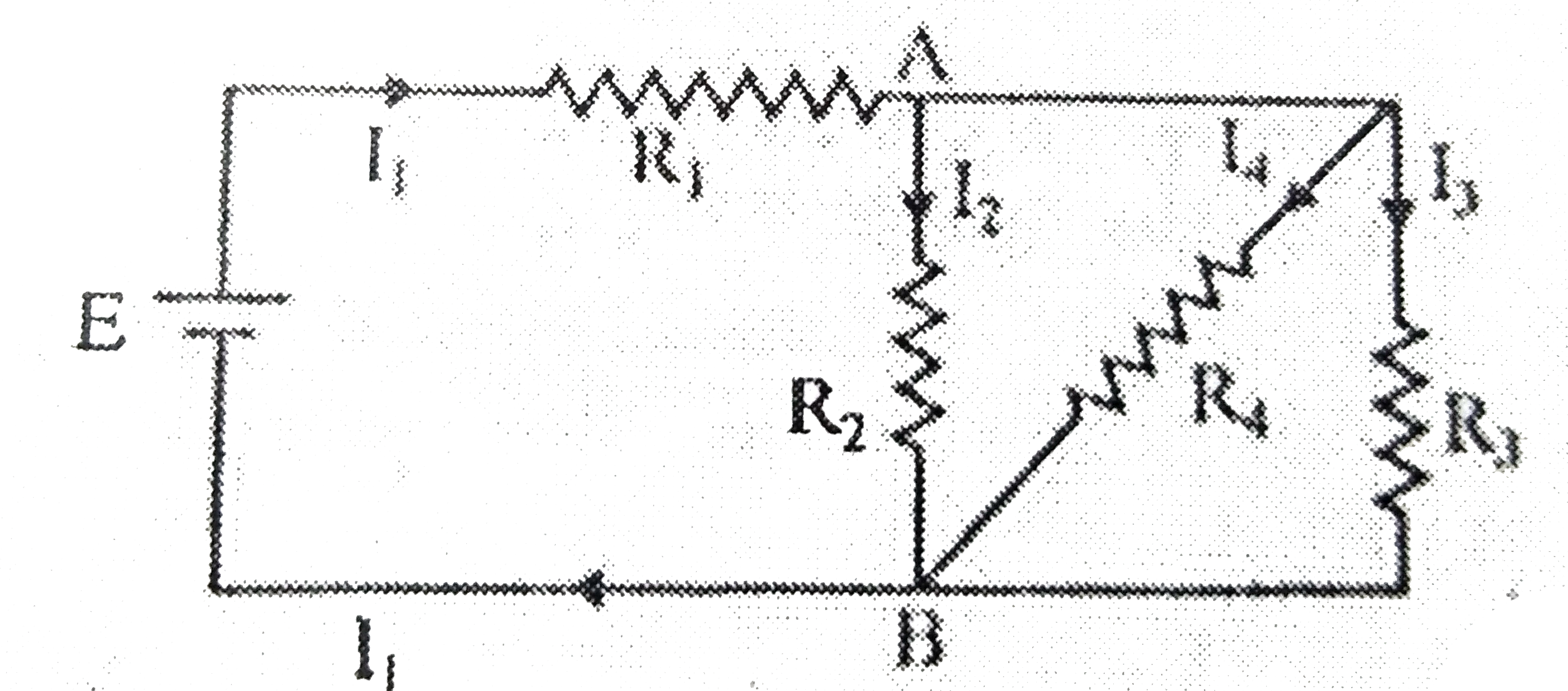
In the circuit shown, R1=2Ω,R2=R3=10Ω,R4=20ΩandE=6V. Work out the equivalent resistance of the circuit and the current in each resistor.
 View Solution
In the circuit shown, R1=2Ω,R2=R3=10ΩandE=6V. Work out the equivalent resistance of the circuit and the current in each resistor.
 View Solution
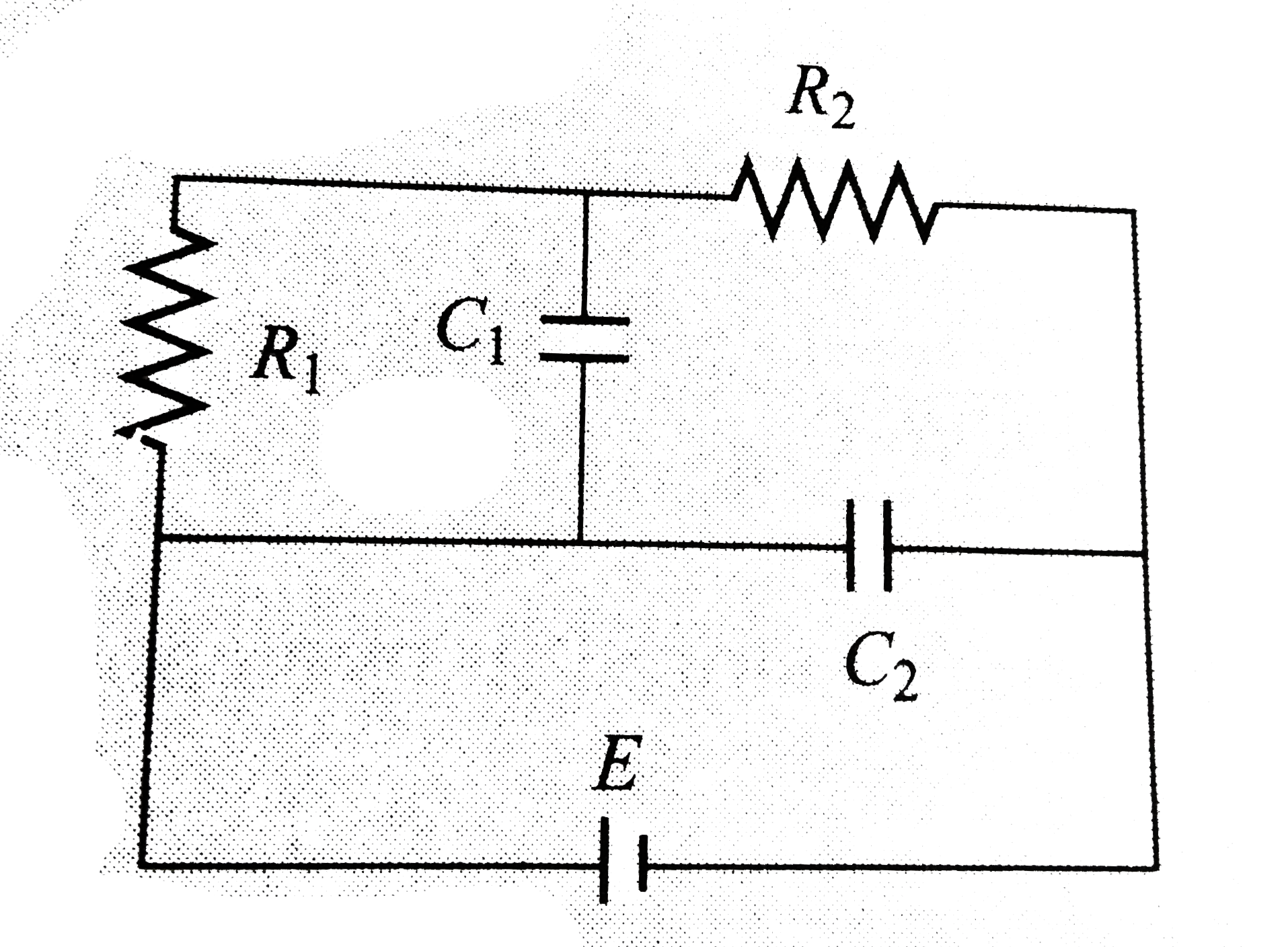
In the circuit shown in fig. R1=10Ω,R2=5Ω,C1=1μF,C2=2μF, and E =6V. Calculate the charge on each capactor in the stedy state.
 View Solution

