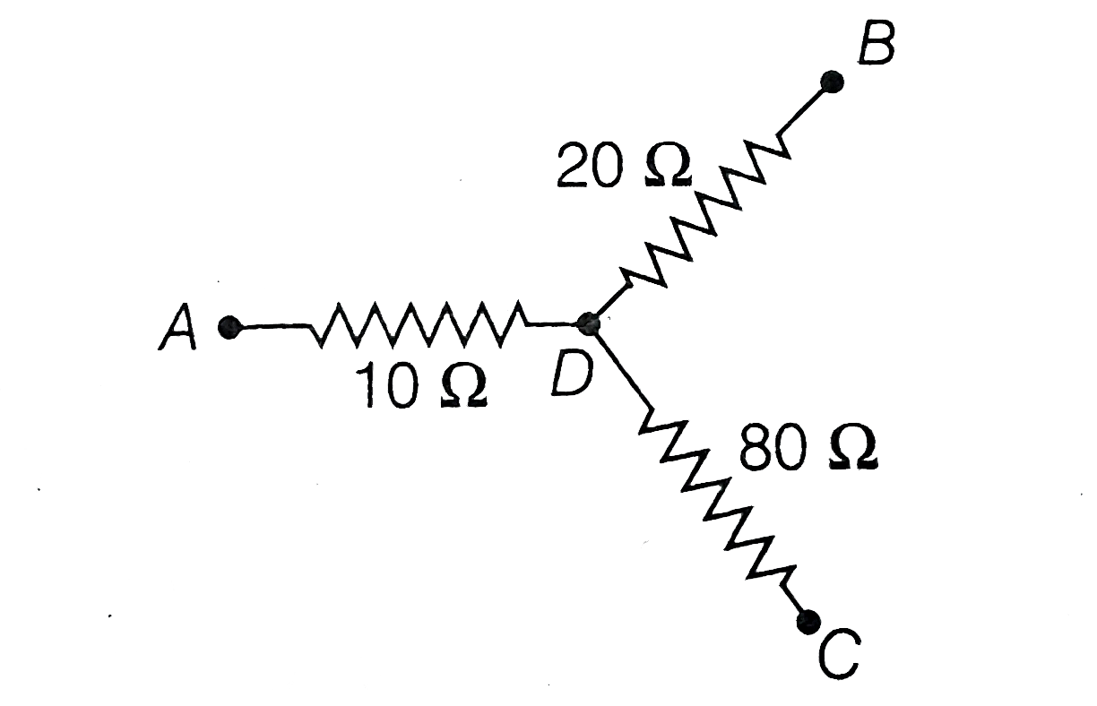
In the network shown in fig. , points A, B, and C are at potentials of 70 V, 0, and 10V, respectively.
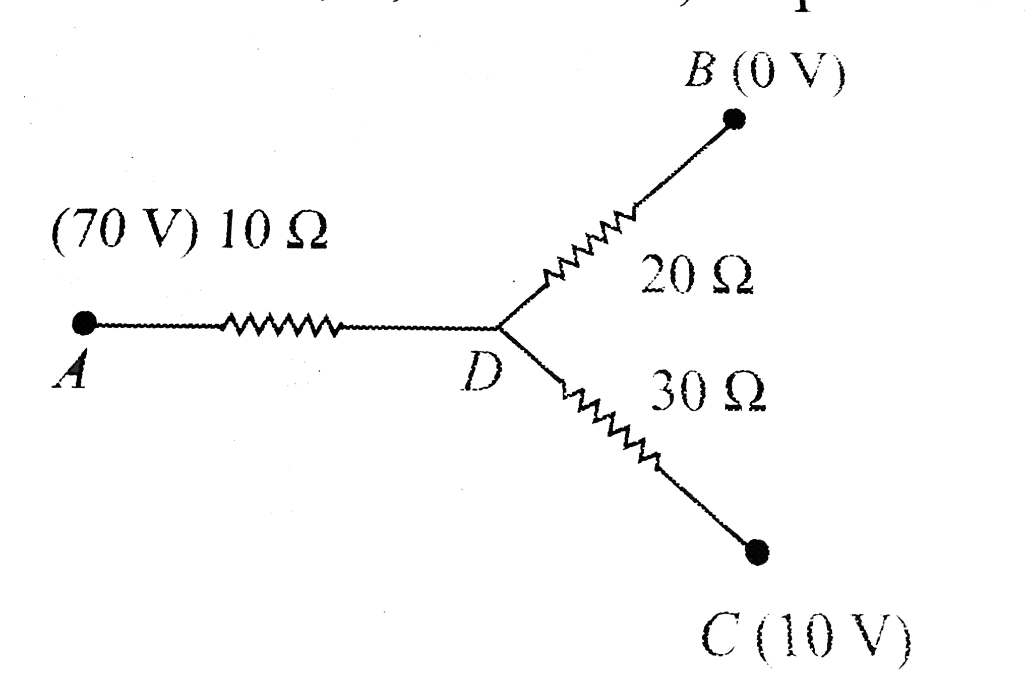
Point D is at a potential of 40V.
The currents in the sections AD,DB,DC are int eh ratio 3:2:1
The currents in the sections AD,DB,DC are in the ratio 1:2:3
The network draws a total power of 200W
The correct Answer is:A, B, D
Step by step video, text & image solution for In the network shown in fig. , points A, B, and C are at potentials of 70 V, 0, and 10V, respectively. by Physics experts to help you in doubts & scoring excellent marks in Class 12 exams.
Updated on:21/07/2023Topper's Solved these Questions
Similar Questions
Knowledge Check
For the network shown in figure, points A, B and C are at potentials of 70 V, zero and 10 V respectively
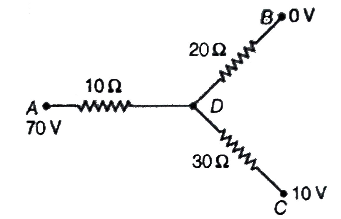 Apoint D is at a potential of 40 VBthe currents in the sections AD, DB and DC are in the ratio 4:3:2Cthe current in the sections AD, DB and DC are in the ratio 1:2:3Dthe network draws a total power of 100 W
In the network shown in fig. , the potential differene across A and B is
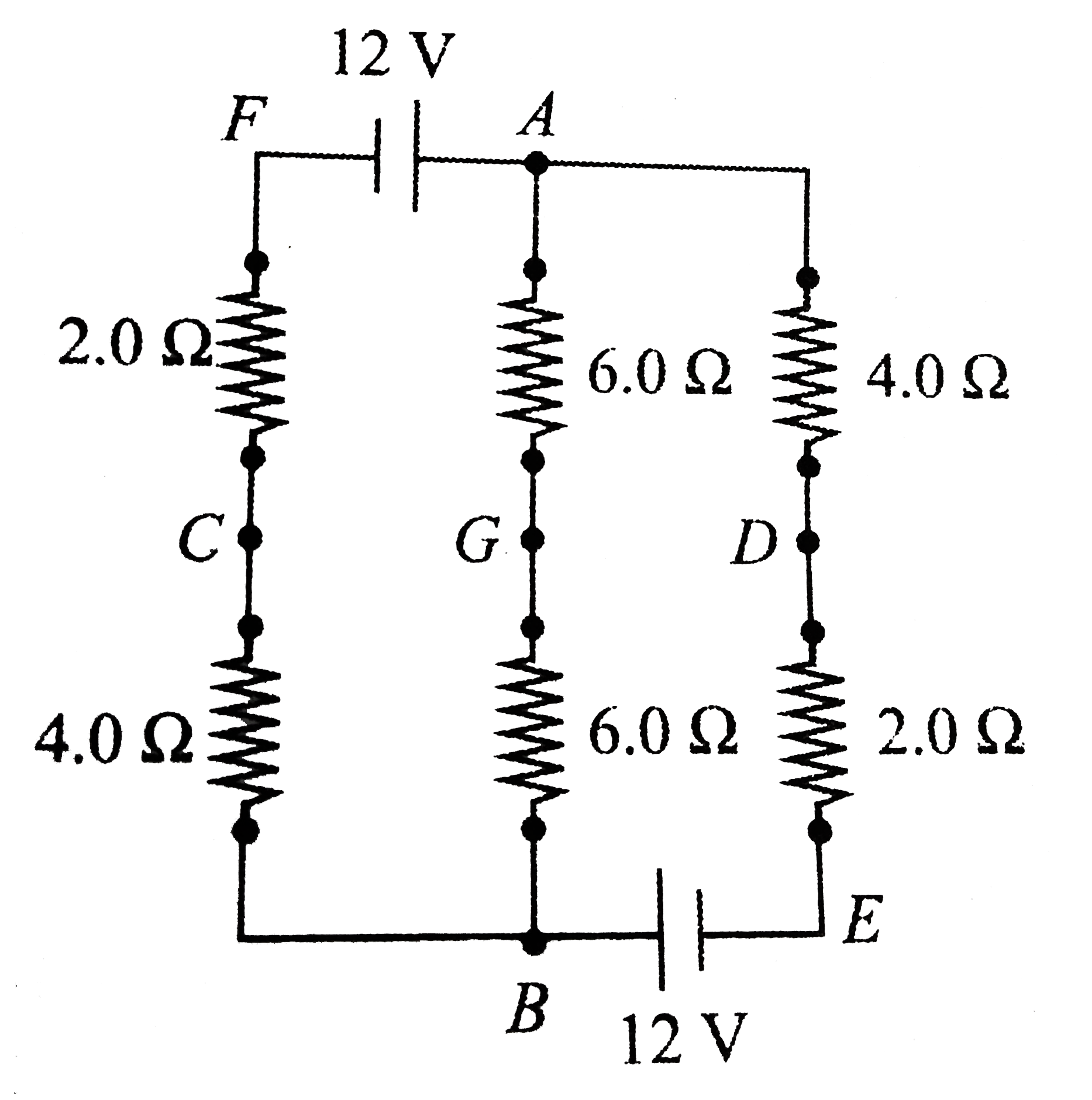 A6VBzeroC2VD4V
A hollow conducting sphere is placed in an electric field produced by a point charge placed at P as shown in figure.
Let VA,VB,VC be the potentials at points A,BandC respectively. Then
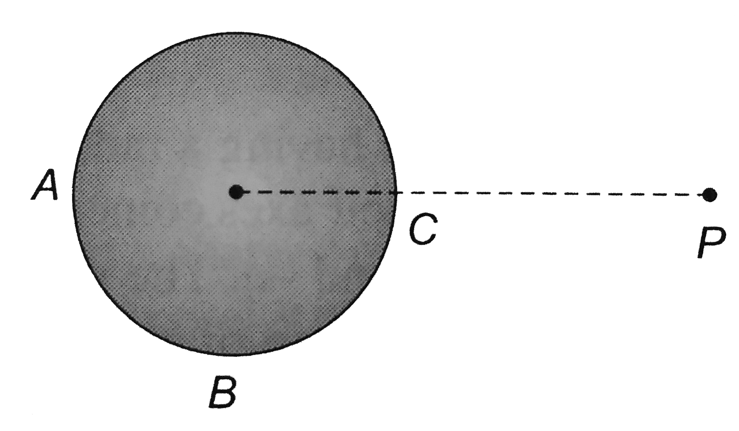 AVC>VBBVB>VCCVA>VBDVA=VC
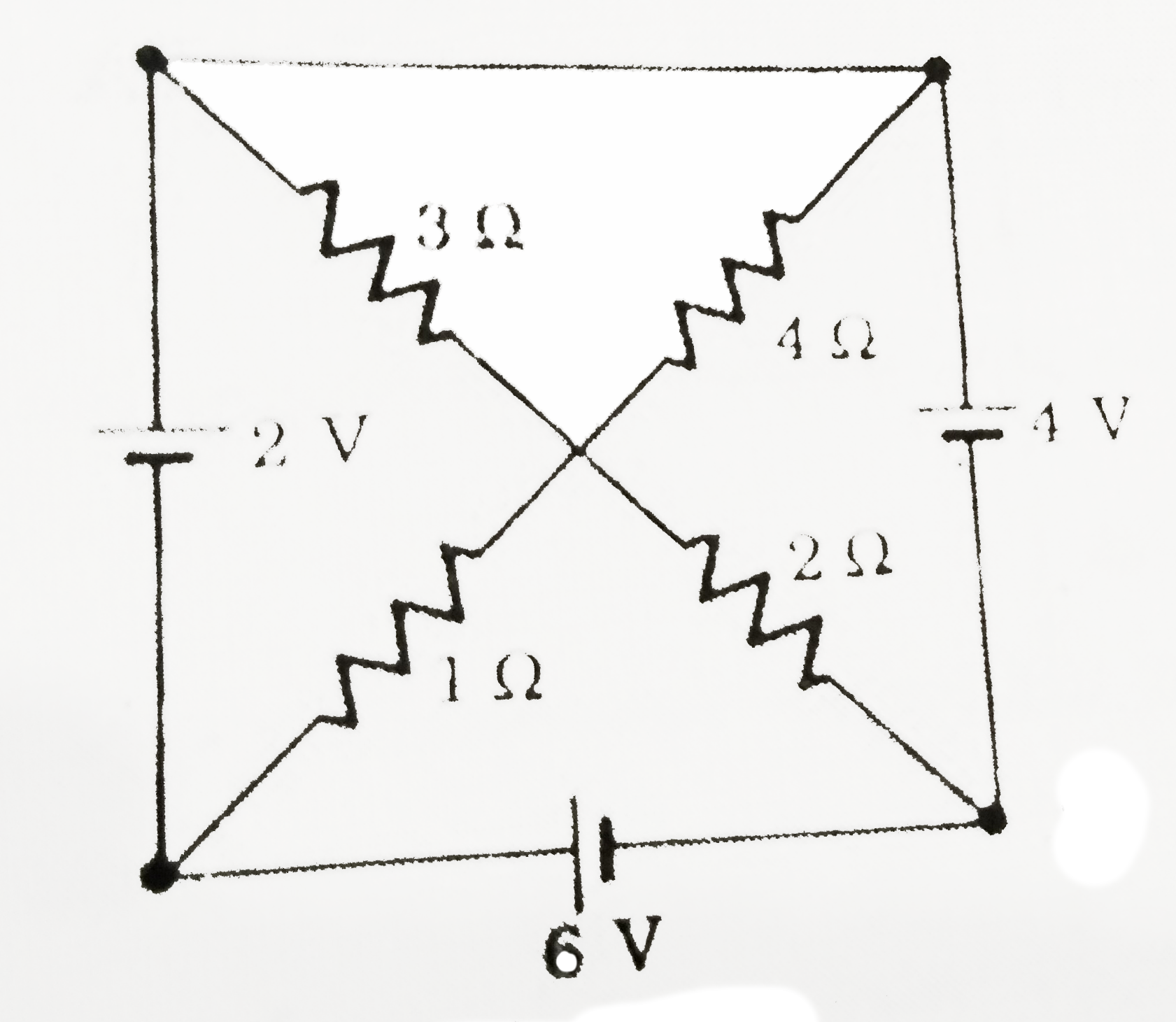
In the network shown in figure. (i) calculate the current of the 6V battery and (ii) determine the potential difference between the points A and B.
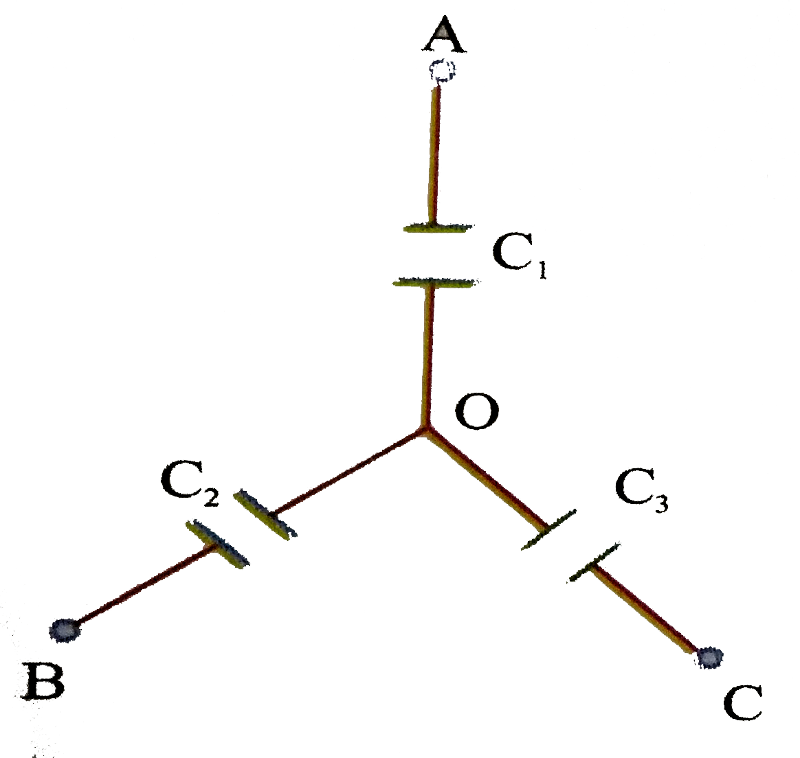
View SolutionThree uncharged capacitors of capacities C1,C2 and C3 are connected as shown in the figure to one another and the potentials V1,V2 and V3 respectively. Then the potential at O will be
 .
.
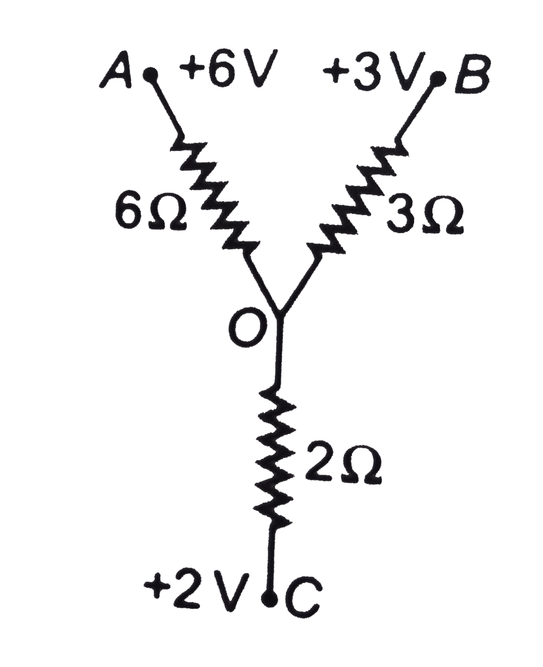
View SolutionThree resistance are joined together to form a letter Y, as shown in figure. If the potentials of the terminals A,B and C are 6V,3V and 2V respectively, then the potential of the point O will be
View SolutionTwo points P and Q are maintained at the potentials of 10V and -4V, respectively. The work done in moving 100 electrons from P to Q is:
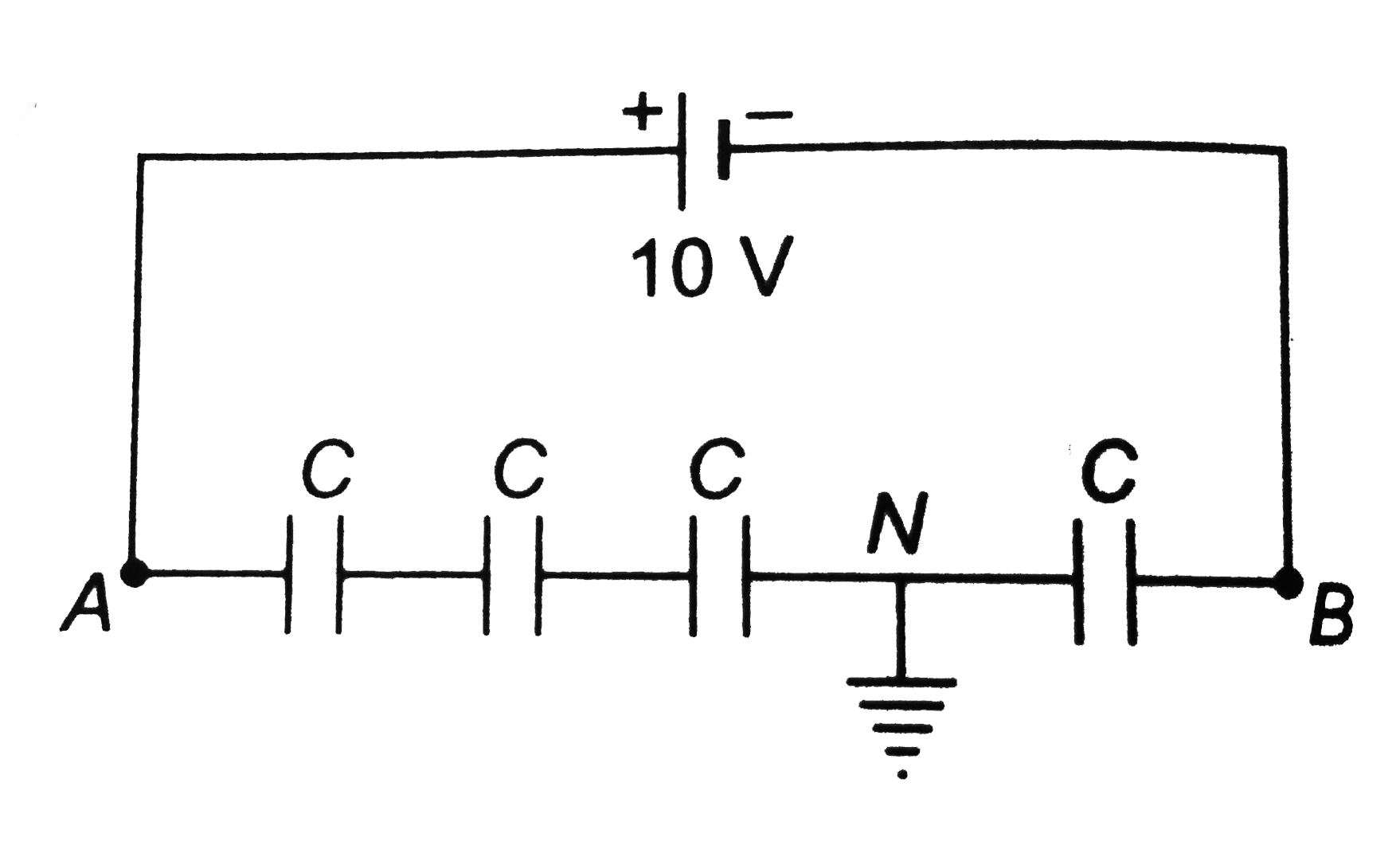
View SolutionFour identical capacitors are connected in series with a 10V battery as shown in the figure. The point N is earthed. The potentials of points A and B are
View Solution
 .
.