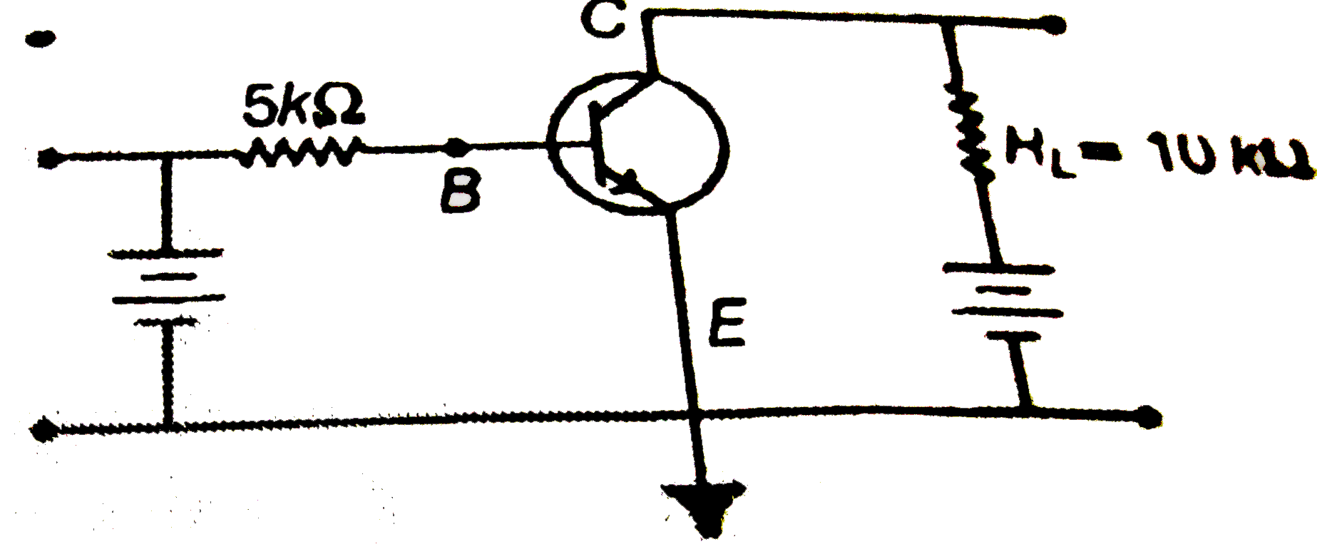
The adjoining diagram shows the biasing of an npn-transistor in common emitter configuration used in an amplifer. The design of the transistor is such that 98% of the charge carries passing through the emitter reach the collector. If base current changes from 50μA to 100μA, then the corresponding change in the voltage across the load resistance RL will be

0.25 V
0.5 V
24.5 V
49.0 V
The correct Answer is:C
Topper's Solved these Questions
- SEMICONDUCTORS AND ELECTRONIC DEVICESBOOK - DC PANDEYCHAPTER - SEMICONDUCTORS AND ELECTRONIC DEVICESEXERCISE - More than One Option is Correct
3 Videos
- ROTATIONAL MOTIONBOOK - DC PANDEYCHAPTER - ROTATIONAL MOTIONEXERCISE - Integer Type Questions
17 Videos
- SIMPLE HARMONIC MOTIONBOOK - DC PANDEYCHAPTER - SIMPLE HARMONIC MOTIONEXERCISE - Integer type questions
14 Videos
Similar Questions
Consider an n−p−n transistor amplifer in common-emitter configuration. The current gain of the transistor is 100. If the collector current changes by 1mA, what will be the change in emitter current?
View SolutionA transistor is operated in common emitter configuration at constant collector voltage Vc=1.5V such that a change in the base current from 100μA to 150μA produces a change in the collector current from 5mA to 10mA. The current gain (β) is
View Solution
Knowledge Check
For a transistor in common emitter configuration, the current amplification factor is 4 . If the transistor is connected in the common base connected and change in emitter current be 6mA, then the collector current will be
A2.4 mAB3.6 mAC4.8 mAD7.2 mAConsider an n−p−n transistor amplifer in common-emitter configuration. The current gain of the transistor is 100. If the collector current changes by 1mA, what will be the change in emitter current?
A1.01mAB1.1mAC0.01mAD10mAA transistor is operated in common emitter configuration at constant collector voltage Vc=1.5V such that a change in the base current from 100μA to 150μA produces a change in the collector current from 5mA to 10mA. The current gain (β) is
A67B75C100D50
A transistor is operated in common emitter configuration at constant collector voltage Vc=1.5V such that a change in the base current from 100 μA to 150 μA produces a change in the collector current from 5 mA to 10 mA. The current gain (β) is :-
View SolutionA transistor is used in common emitter configuration. Given its α=0.9, calculate the change in collector current when the base current changes by 2μA.
View SolutionA transistor is used in common emitter configuration. Given its α=0.9, calculate the change in collector current when the base current changes by 2μA.
View SolutionA transistor is operated in common emitter configuration at VC=2V. Such that a change in the base current from 100μA to 200μA produces a change in the collector current of 5mA to 10 mA. The current gain is
View SolutionA transistor is operated in common emitter configuration at VC=2V. Such that a change in the base current from 100μA to 200μA produces a change in the collector current of 5mA to 10 mA. The current gain is
View Solution
