The carrier freqeuncy of a station is 40 MHz. A resistor of 10k and capacitor of CpF are available in the detector circuit. The possible value of C will be
12
8.2
5.6
All of these
The correct Answer is:D
To solve the problem, we need to determine the possible value of the capacitor C in the detector circuit, given the carrier frequency and the resistance. Here’s a step-by-step breakdown of the solution:
Step 1: Identify Given Values
- Carrier frequency fc=40 MHz
- Resistance R=10 kΩ
Step 2: Convert Units
Convert the carrier frequency from MHz to Hz:
fc=40 MHz=40×106 Hz=4×10⁷ Hz
Convert the resistance from kΩ to Ω:
R=10 kΩ=10×103 Ω=104 Ω
Step 3: Calculate the Time Period
The time period T of the carrier frequency is the reciprocal of the frequency:
T=1fc=14×107=2.5×10⁻⁸ seconds
Step 4: Determine the Time Constant
The time constant τ for an RC circuit is given by:
τ=R×C
Where C is in farads.
Step 5: Set Up the Condition
For the detection circuit to work effectively, the time period T should be less than the time constant τ:
T<τ
This implies:
2.5×10⁻⁸<R×C
Step 6: Substitute the Values
Substituting the value of R:
2.5×10⁻⁸<104×C
Rearranging gives:
C>2.5×10−8104=2.5×10⁻¹² F=2.5 pF
Step 7: Evaluate Possible Values of C
Now, we will evaluate the provided options for C (12 pF, 8.2 pF, and 5.6 pF):
1. For 12 pF:
τ=104×12×10−12=1.2×10⁻⁷ seconds
T<τ is satisfied.
2. For 8.2 pF:
τ=104×8.2×10−12=8.2×10⁻⁸ seconds
T<τ is satisfied.
3. For 5.6 pF:
τ=104×5.6×10−12=5.6×10⁻⁸ seconds
T<τ is satisfied.
Conclusion
All options provided (12 pF, 8.2 pF, and 5.6 pF) satisfy the condition T<τ. Therefore, the possible values of C can be any of the given options.
- Carrier frequency fc=40 MHz
- Resistance R=10 kΩ
Convert the carrier frequency from MHz to Hz:
fc=40 MHz=40×106 Hz=4×10⁷ Hz
Convert the resistance from kΩ to Ω:
R=10 kΩ=10×103 Ω=104 Ω
The time period T of the carrier frequency is the reciprocal of the frequency:
T=1fc=14×107=2.5×10⁻⁸ seconds
The time constant τ for an RC circuit is given by:
τ=R×C
Where C is in farads.
For the detection circuit to work effectively, the time period T should be less than the time constant τ:
T<τ
This implies:
2.5×10⁻⁸<R×C
Substituting the value of R:
2.5×10⁻⁸<104×C
Rearranging gives:
C>2.5×10−8104=2.5×10⁻¹² F=2.5 pF
Now, we will evaluate the provided options for C (12 pF, 8.2 pF, and 5.6 pF):
1. For 12 pF:
τ=104×12×10−12=1.2×10⁻⁷ seconds
T<τ is satisfied.
τ=104×8.2×10−12=8.2×10⁻⁸ seconds
T<τ is satisfied.
τ=104×5.6×10−12=5.6×10⁻⁸ seconds
T<τ is satisfied.
All options provided (12 pF, 8.2 pF, and 5.6 pF) satisfy the condition T<τ. Therefore, the possible values of C can be any of the given options.
Topper's Solved these Questions
- COMMUNITCATION SYSTEMSBOOK - NCERT FINGERTPS ENGLISHCHAPTER - COMMUNITCATION SYSTEMSEXERCISE - NCERT
9 Videos
- COMMUNITCATION SYSTEMSBOOK - NCERT FINGERTPS ENGLISHCHAPTER - COMMUNITCATION SYSTEMSEXERCISE - CORNER
15 Videos
- COMMUNITCATION SYSTEMSBOOK - NCERT FINGERTPS ENGLISHCHAPTER - COMMUNITCATION SYSTEMSEXERCISE - Assertion And Reason
30 Videos
- ATOMS BOOK - NCERT FINGERTPS ENGLISHCHAPTER - ATOMS EXERCISE - Assertion And Reason
15 Videos
- CURRENT ELECTRICITYBOOK - NCERT FINGERTPS ENGLISHCHAPTER - CURRENT ELECTRICITYEXERCISE - Assertion And Reason
15 Videos
Similar Questions
An inductor of 10mH is connected to a 18V battery through a resistor of 10kΩ and a switch After a long time, when the maximum current is set up in the circuit, the current is switched off. Calculate the cur- rent in the circuit after 2 μs.
View SolutionAn alternating current of 1.5 mA and angular frequency omega = 300 rad/s flows through 10 Omega resistor and a 0.50 muF capacitor in series. Find the r.m.s. voltage across the capacitor and impedance of the circuit
View Solution
Knowledge Check
The carrier freqeuncy of a station is 40 MHz. A resistor of 10k Ω and capacitor of 12 pF are available in the detector circuit. The possible value of C will be
A12B8.2C5.6DAll of theseIn a diode AM detector with the output circuit consists of R=1MΩ and C=1pF would be more suitable for detecting a carrier signal of
A1MHzB0.1 MHzC0.5MHzD10MHzA 0.2kΩ resistor and 15μF capacitor are connected in series to a 220 V, 50 Hz ac source. The impadance of the circuit is
A250ΩB268ΩC29.15ΩD291.5Ω
An a.c. source of angular frequency ω is fed across a resistor R and a capacitor C in series. The current registered is I. If now the frequency of the source is changed to ω/3 (but maintaining the same voltage), the current in the circuit is found to be halved. calculate the ratio of reactance to resistance at the original frequency ω.
View SolutionThe natural frequency of an LC- circuit is 1,25,000 cycles per second. Then the capacitor C is replaced by another capacitor with a dielectric medium of dielectric constant k. In this case, the frequency decreases by 25 kHz. The value of k is
View SolutionAn alternating e.m.f of 220V is applied to a circuit containing a resistor R having resistance of 160Ω and a capacitor .C. in series. The current is found to lead the supply voltage by an angle θ=tan−1(3/4)
Calculate: Impedance of the circuit
View SolutionAn alternating e.m.f of 220V is applied to a circuit containing a resistor R having resistance of 160Ω and a capacitor .C. in series. The current is found to lead the supply voltage by an angle θ=tan−1(3/4)
Calculate: Current flowing in the circuit
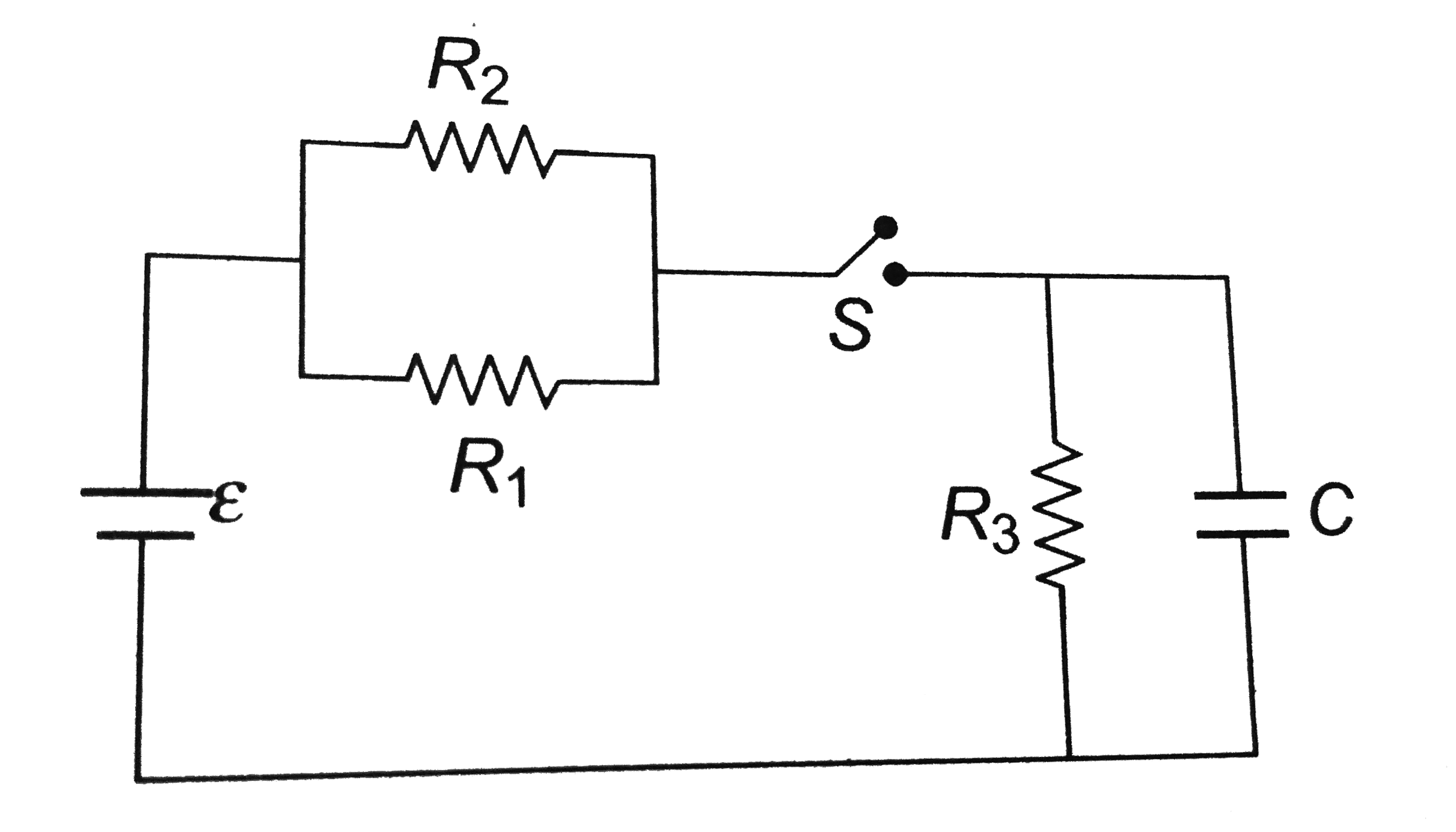
View SolutionThe circuit shown in the figure consists of a battery of emf ε=10V , a capacitor of capacitance C=1.0μF and three resistors of value R1=2Ω,R2=2Ω and R3=1Ω, Initially the capacitor is completely uncharged and the switch S is open. The switch S is closed at t=0. Then

View Solution
