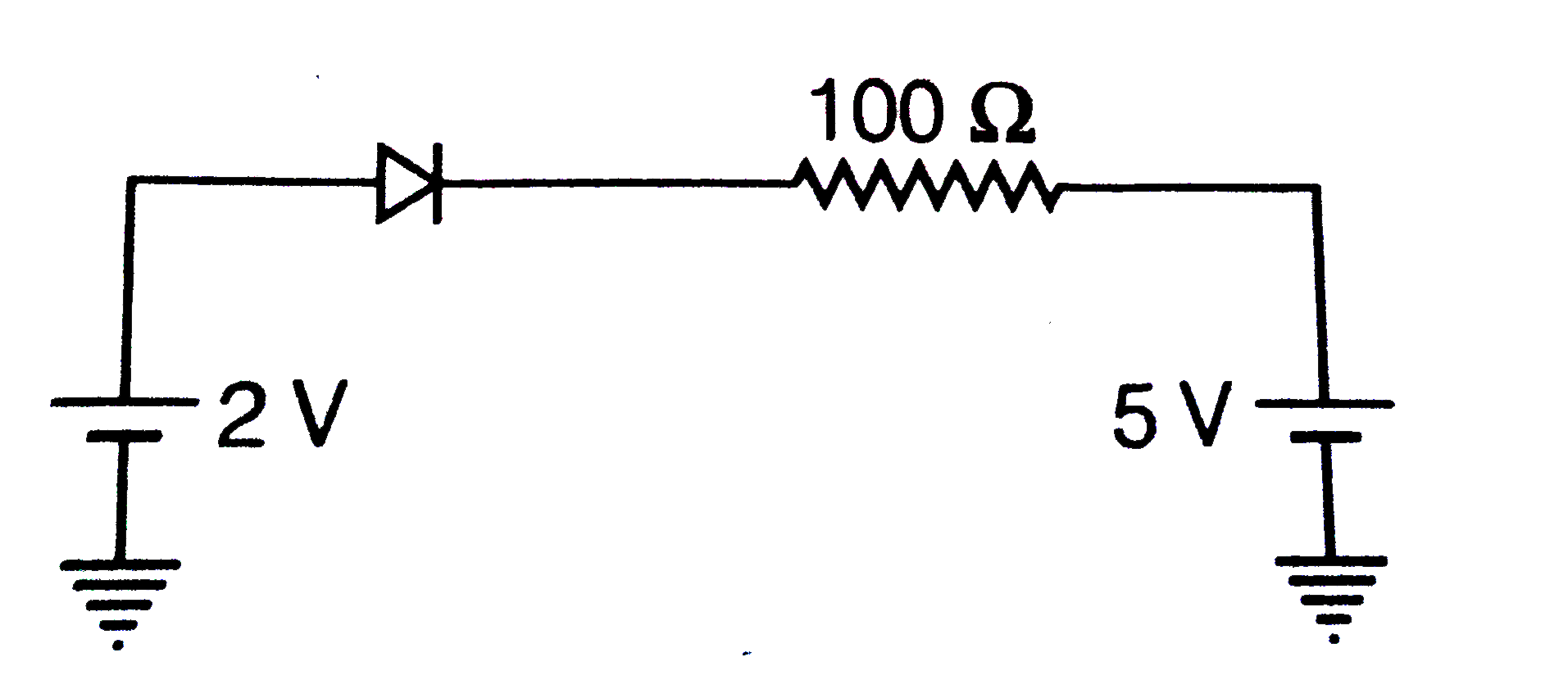
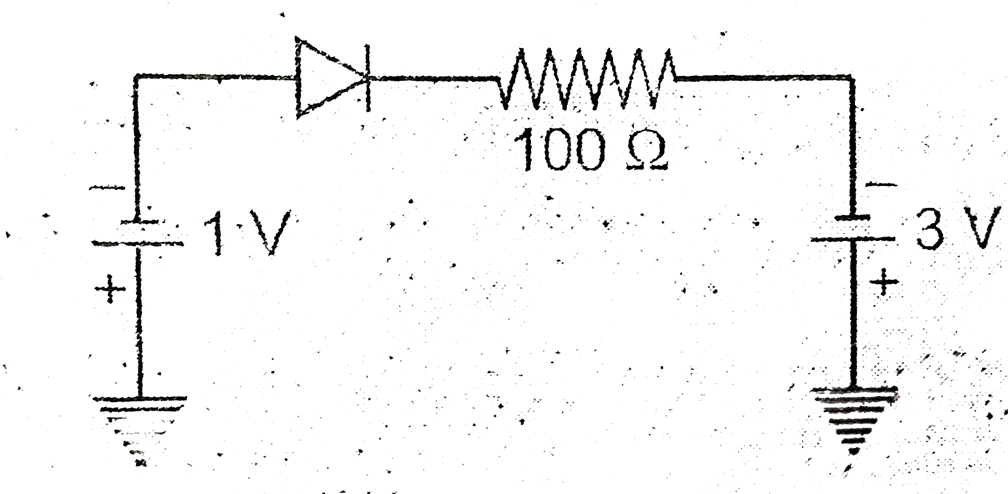
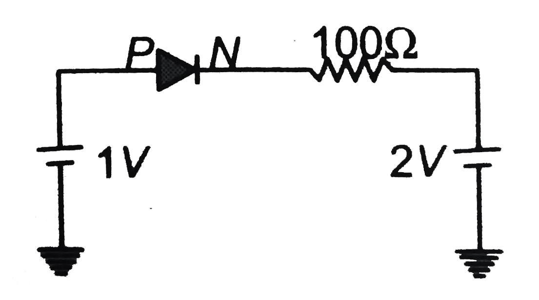
The current through an ideal PN-junction shown in the following circuit diagram will be
A
zero
B
1mA
C
10mA
D
30mA
Video Solution
Text Solution
The correct Answer is:A
The diode is in reverse biasing so current through it is zero.
|
Topper's Solved these Questions
- SEMICONDUCTOR ELECTRONICSBOOK - A2ZCHAPTER - SEMICONDUCTOR ELECTRONICSEXERCISE - Junction Transistor
47 Videos
- SEMICONDUCTOR ELECTRONICSBOOK - A2ZCHAPTER - SEMICONDUCTOR ELECTRONICSEXERCISE - Digital Electronics
40 Videos
- SEMICONDUCTOR ELECTRONICSBOOK - A2ZCHAPTER - SEMICONDUCTOR ELECTRONICSEXERCISE - Junction Diode
57 Videos
- NUCLEAR PHYSICSBOOK - A2ZCHAPTER - NUCLEAR PHYSICSEXERCISE - Section D - Chapter End Test
29 Videos
- SOURCE AND EFFECT OF MAGNETIC FIELDBOOK - A2ZCHAPTER - SOURCE AND EFFECT OF MAGNETIC FIELDEXERCISE - Section D - Chapter End Test
30 Videos
Similar Questions
Knowledge Check
The current through and ideal p-n junction shown in the following circuit diagram will be
 AzeroB1 mAC10 mAD30 mA
The current through the ideal diode as shown in the is
 A0AB0.02AC0.04AD0.06A
In a PN-junction
AP and N both are at same potentialBHigh potential at N side and low potential at P sideCHigh potential P side and low potential at N sideDLow potential at N side and zero potential at P side
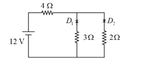
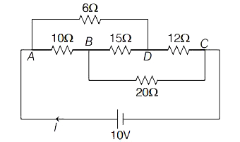
The current through the battery shown in the circuit is
View SolutionIn a PN-junction
View SolutionThe current through the ideal diode as shown in the figure is

View SolutionCurrent through the ideal diode as shown in figure is

View SolutionThe value of current I as shown in the given circuit diagram is
View Solution

