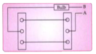
The diagram given below (Fig.) shows a bulb connected with a cell having terminals A and B. Mark the direction of current in the bulb.
To determine the direction of current in the bulb connected to a cell with terminals A and B, follow these steps:
1. Identify the Terminals:
- First, recognize that the cell has two terminals: A (positive terminal) and B (negative terminal).
2. Understand Current Flow:
- Current in a circuit flows from the positive terminal to the negative terminal. This is a fundamental principle of electricity.
3. Connect the Bulb:
- The bulb is connected to the cell. When the circuit is closed, the current will flow through the bulb.
4. Mark the Direction of Current:
- Since the current flows from the positive terminal (A) to the negative terminal (B), you will mark the direction of current entering the bulb from the terminal connected to A and exiting through the terminal connected to B.
5. Conclusion:
- Therefore, the direction of current in the bulb is from the positive terminal (A) to the negative terminal (B).
Final Answer:
The direction of current in the bulb is from terminal A (positive) to terminal B (negative).
---
- First, recognize that the cell has two terminals: A (positive terminal) and B (negative terminal).
- Current in a circuit flows from the positive terminal to the negative terminal. This is a fundamental principle of electricity.
- The bulb is connected to the cell. When the circuit is closed, the current will flow through the bulb.
- Since the current flows from the positive terminal (A) to the negative terminal (B), you will mark the direction of current entering the bulb from the terminal connected to A and exiting through the terminal connected to B.
- Therefore, the direction of current in the bulb is from the positive terminal (A) to the negative terminal (B).
The direction of current in the bulb is from terminal A (positive) to terminal B (negative).
Topper's Solved these Questions
- ELECTRICITY AND MAGNETISM BOOK - ICSECHAPTER - ELECTRICITY AND MAGNETISM EXERCISE - QUESTION (Write T for True and F for False. Correct the false statements)
4 Videos
- ELECTRICITY AND MAGNETISM BOOK - ICSECHAPTER - ELECTRICITY AND MAGNETISM EXERCISE - QUESTION (Choose the correct option to fill in the blanks)
5 Videos
- ELECTRICITY AND MAGNETISM BOOK - ICSECHAPTER - ELECTRICITY AND MAGNETISM EXERCISE - TEST YOURSELF (OBJECTIVE QUESTIONS :) (SELECT THE CORRECT ALTERNATIVE:)
8 Videos
- ENERGYBOOK - ICSECHAPTER - ENERGYEXERCISE - EXERCISE (PICTURE STUDY)
3 Videos
Similar Questions
The diagram given below shows the supportive connective tissue.

Identify the tissues A and B.
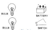
View SolutionFrom the figures given below, identify the bulbs connected in parallel and in series.

View SolutionDraw a circuit diagram for a bulb connected to a cell with a switch. Mark arrows in the diagram to indicate the direction of flow of current.
View SolutionThe diagram given below shows the supportive connective tissue.

Draw neat diagrams of the three types of blood cells.
View SolutionThe diagram in Fig. shows a battery, a switch and two bulbs.
(a) Complete the diagram to show the electric connections of the bulbs to the battery.
How have you joined the bulbs in part (a) ? Give reason.

View SolutionThe diagram below shows a dual control switch circuit connected to a bulb.

Copy the diagram and complete it so that the bulb is switched ON.
View Solution(a) Complete the circuit given in Fig. 1 by inserting between the terminals A and C, an ammeter. (b) In the diagram mark the polarity at the terminals of ammeter and indicate clearly the direction of flow of current in the circuit, when the circuit is complete. (c) Name and state the purpose of Rh in the circuit.

View SolutionThe diagram in Fig. shows a battery, a switch and two bulbs.
Complete the diagram to show the electric connections of the bulbs to the battery.

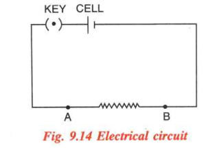
View SolutionYou are given a resistance wire AB connected with a cell and a key as shown in Fig. 9.14. You are required to measure the current in the wire AB and potential difference across it. Name the instruments that you would use and draw a labelled diagram to show how are they connected, Also mark the direction of current in each component.

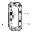
View SolutionThe diagram given below shows a few parts of a cell.

State the difference between the parts labelled A and B on the basis of permeability.
View Solution
