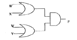
The diagram of a logic circuit is given below. The output of the circuit is represented by
Video Solution
Text Solution
F=(W+X).(W+Y)
=W.W+W.Y+X.W+X.Y=W+W.Y+X.W+X.Y
=W(1+Y)+XW+X.Y=W+XW+X.Y
=W(1+X)+X.Y=W+X.Y
|
Updated on:21/07/2023
Topper's Solved these Questions
- BOOK - AAKASH SERIESCHAPTER - SEMICONDUCTOR DEVICESEXERCISE - EXERCISE -I (ENERGY BANDS AND CLASSIFICATION OF SOLIDS )41videos
SEMICONDUCTOR DEVICES
- BOOK - AAKASH SERIESCHAPTER - SEMICONDUCTOR DEVICESEXERCISE - EXERCISE -I (P-N JUNCTION DIODE)30videos
SEMICONDUCTOR DEVICES
- BOOK - AAKASH SERIESCHAPTER - SEMICONDUCTOR DEVICESEXERCISE - Problems (LEVEL-II)9videos
SEMICONDUCTOR DEVICES
- BOOK - AAKASH SERIESCHAPTER - RAY OPTICSEXERCISE - PROBLEMS ( LEVEL-II)60videos
RAY OPTICS
- BOOK - AAKASH SERIESCHAPTER - UNITS AND MEASUREMENTEXERCISE - PRACTICE EXERCISE45videos
UNITS AND MEASUREMENT
Similar Questions
Knowledge Check
- Question 1 - Select One
The diagram of a logic circuit is given below. The output F of the circuit is represented by
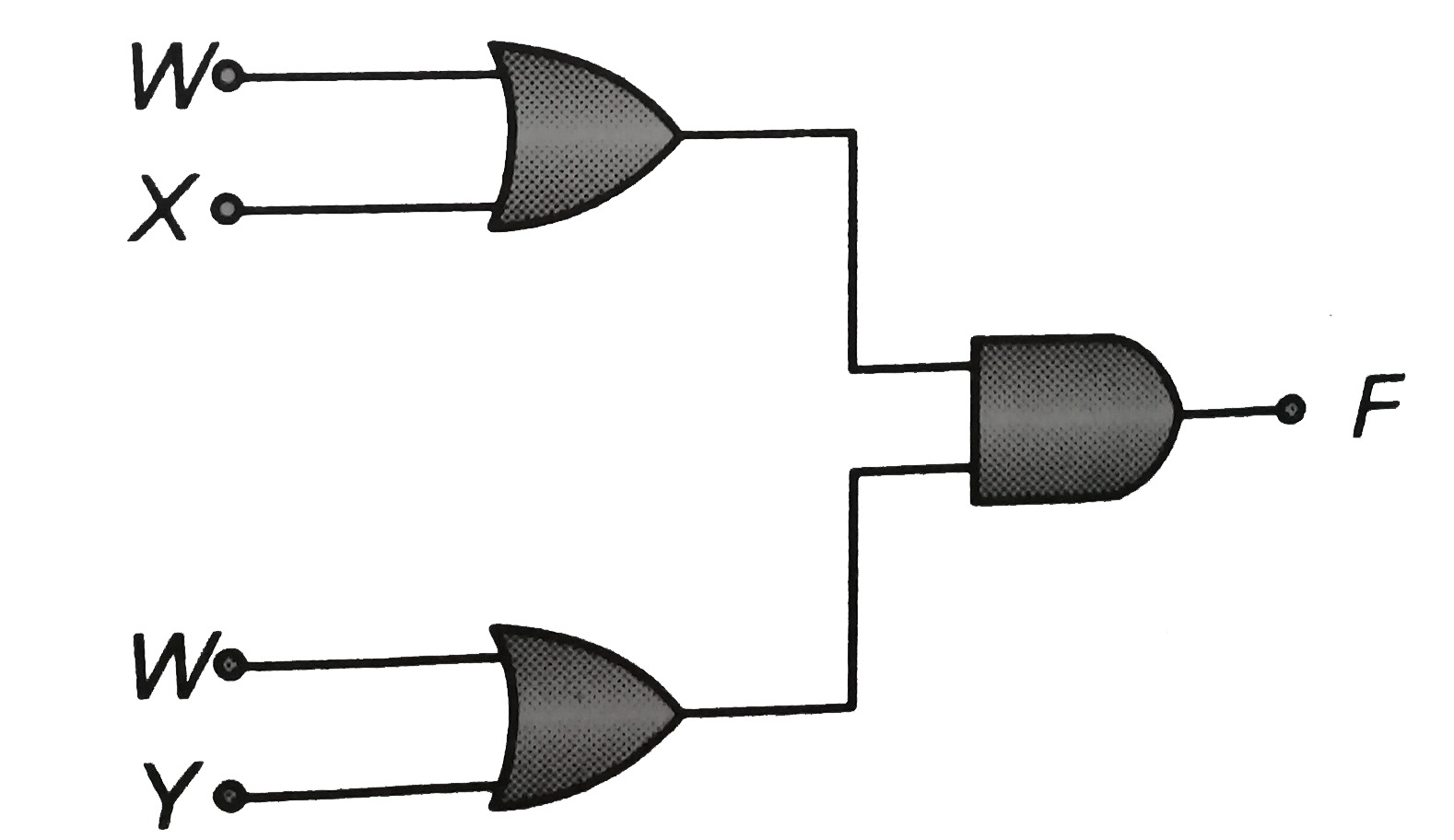 AW.(X+Y)BW.(X.Y)CW+(X.Y)DW+(X+Y)
 - Question 2 - Select One
The output of the given circuit in figure given below,
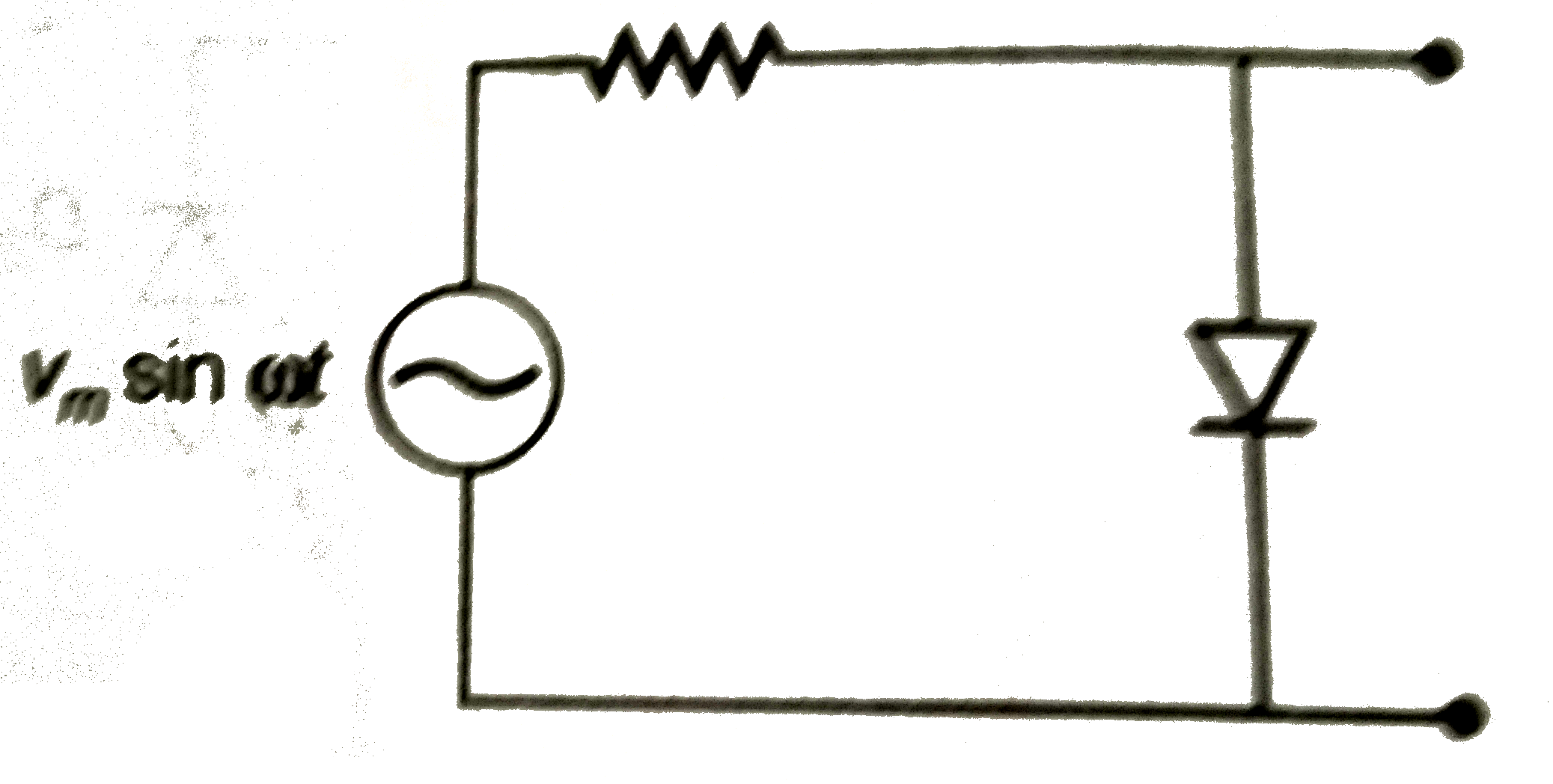 Awould be zero at all times.Bwould be like a half wave rectifier with positive cycles in outputCwould be like a half wave rectifier with negative cycles in output.Dwould be like that of a full wave rectifier.
In the circuit given below, the value of the current is
 View Solution
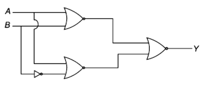
The output of the given logic circuit is
 View Solution
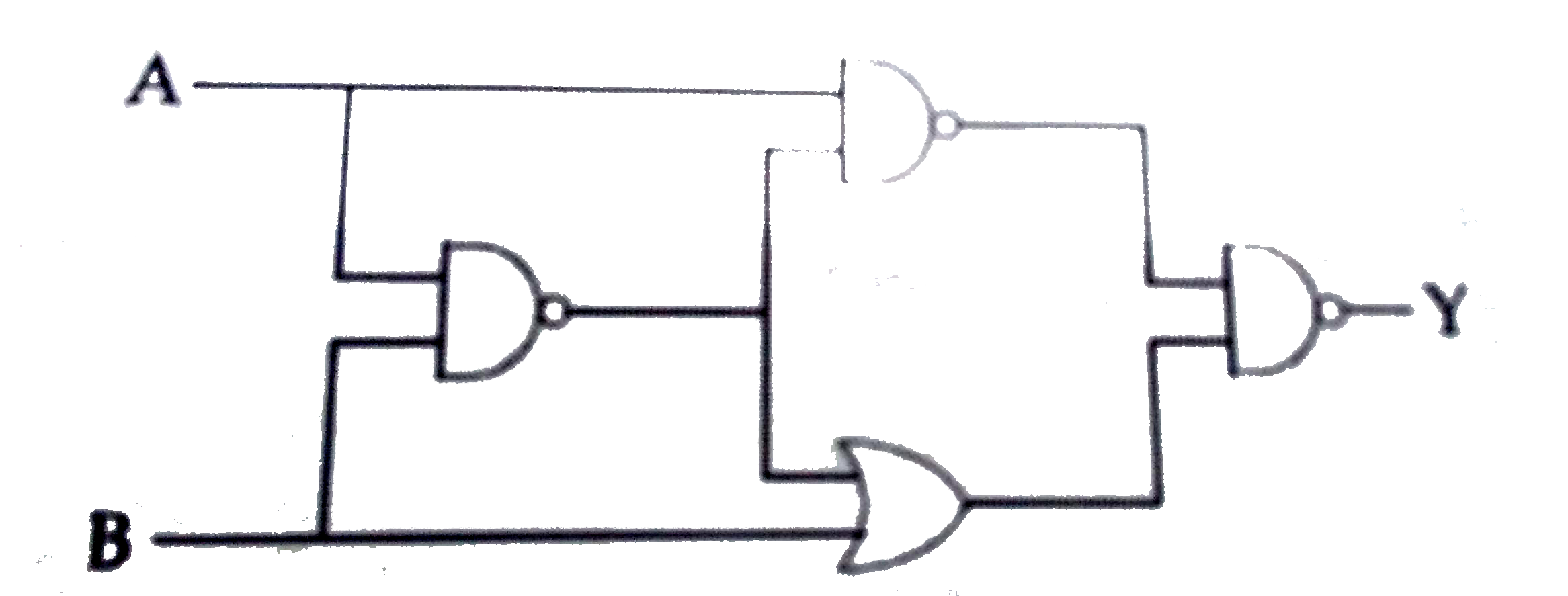
the output given logic circuit is :
 View Solution
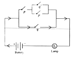
The symbolic form of logic of the circuit given below is
 View Solution
The output of the given circuit in figure given below,
 View Solution
The output of the given logic gate is
 View Solution


