The diode shown in the circuit is a silicon diode. The potential difference between the points A and B will be
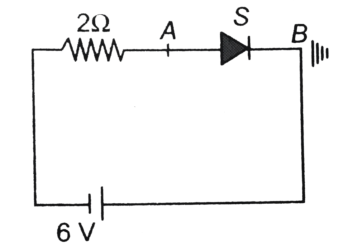
A
6 V
B
0.6 V
C
0.7 V
D
zero
Video Solution
Text Solution
The correct Answer is:A
|
Answer
Step by step video, text & image solution for The diode shown in the circuit is a silicon diode. The potential difference between the points A and B will be by Physics experts to help you in doubts & scoring excellent marks in Class 11 exams.
Updated on:21/07/2023Topper's Solved these Questions
- SEMICONDUCTORS AND ELECTRONIC DEVICESBOOK - DC PANDEYCHAPTER - SEMICONDUCTORS AND ELECTRONIC DEVICESEXERCISE - More than One Option is Correct
3 Videos
- ROTATIONAL MOTIONBOOK - DC PANDEYCHAPTER - ROTATIONAL MOTIONEXERCISE - Integer Type Questions
17 Videos
- SIMPLE HARMONIC MOTIONBOOK - DC PANDEYCHAPTER - SIMPLE HARMONIC MOTIONEXERCISE - Integer type questions
14 Videos
Similar Questions
Knowledge Check
In the circuit shown in figure-3.331, the potential difference between points A and Bis :
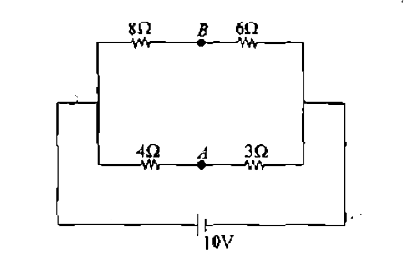 A207VB407VC107VDZero
Potential difference between the points B and E of the circuit is -
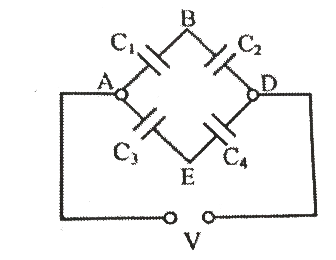 A(C2−C1)VB(C4−C3)VC{C2C3−C1C4C1+C2+C3+C4}D{C1C4−C2C3(C1+C2)(C3+C4)}
In given circuit , the potential difference between points A and B is
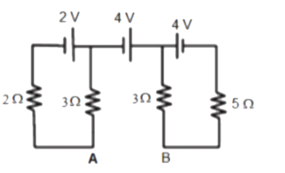 A10 VB15 VC20 VD5V
What is the potential difference between points A and B in the circuit shown?
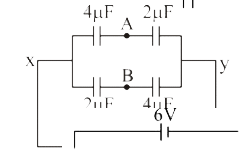
View SolutionIn the circuit shown, the potential difference between A and B is:
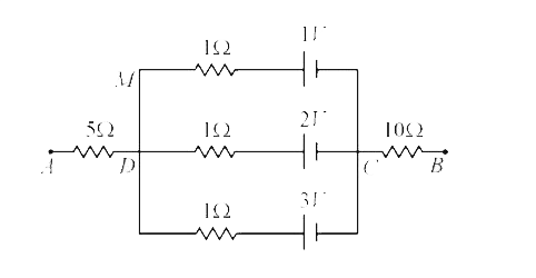
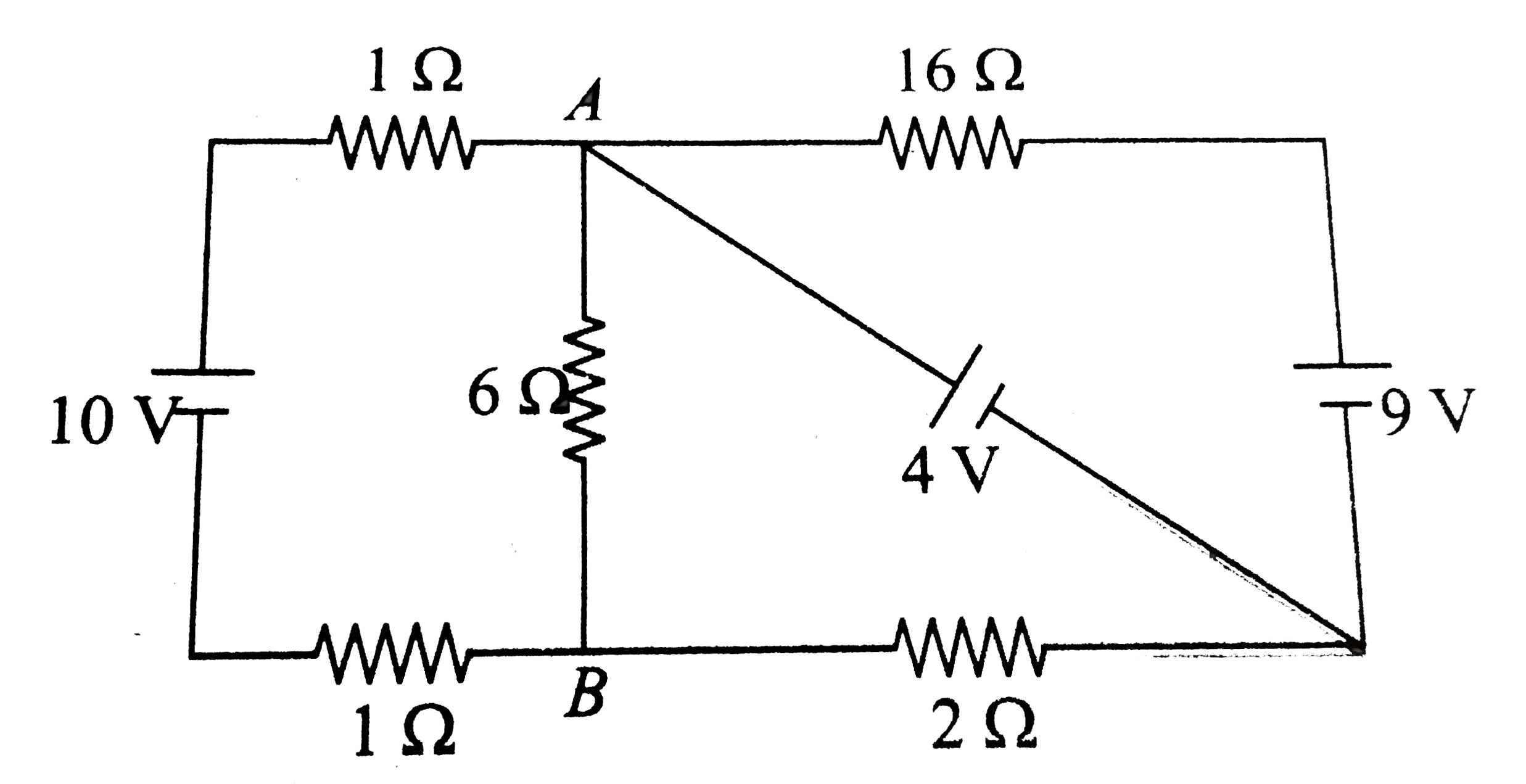
View SolutionFind the potential difference (inV) between points A and B shown in the circuit.
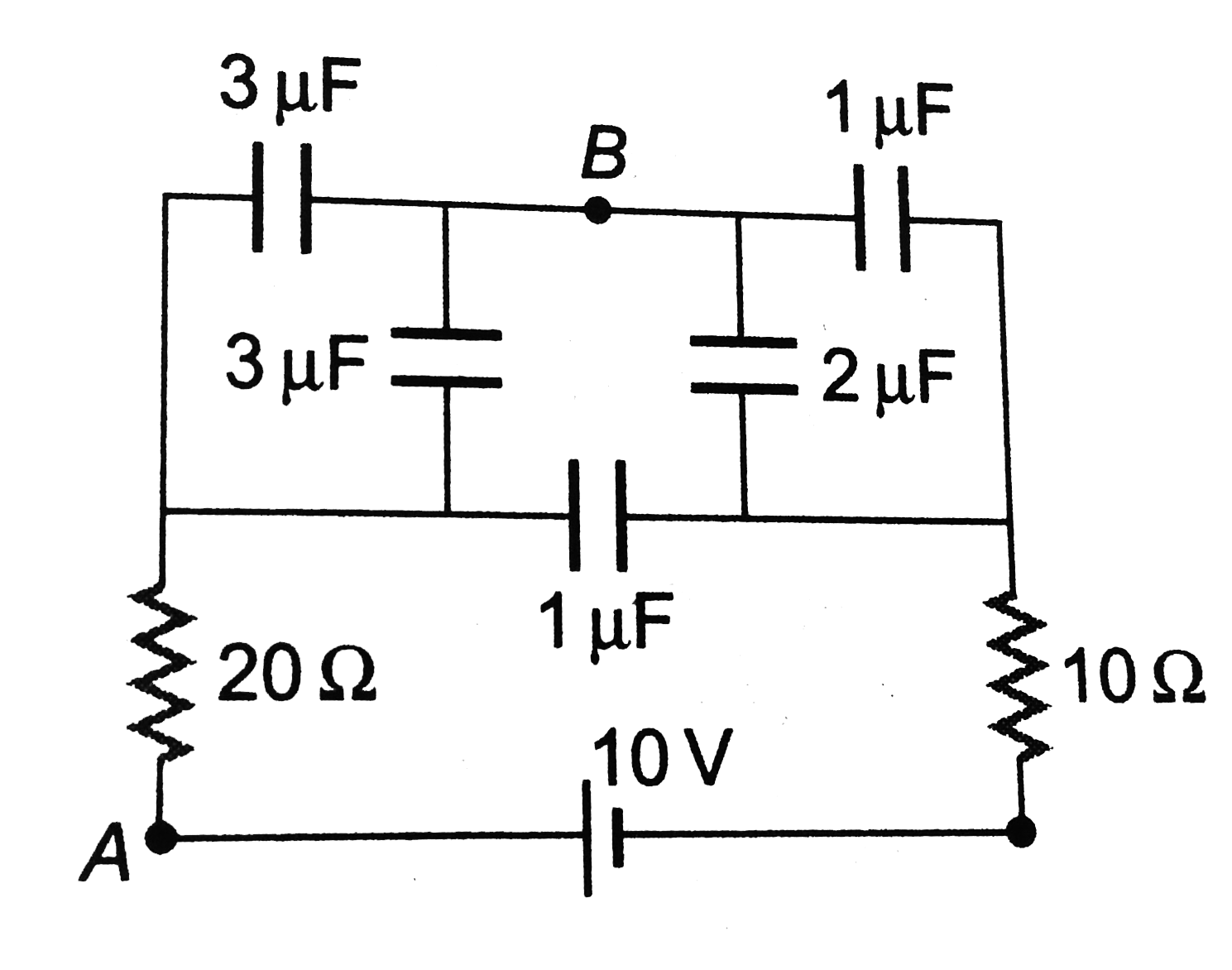
View SolutionIn the circuit shown in figure potential difference between the points A and B in the steady state is
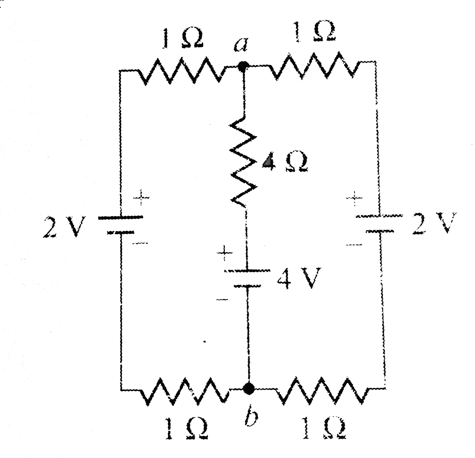
View SolutionFor the circuit given in figure, find the potential difference between points a and b.
View Solution

