The logic symbol shown in figure represents
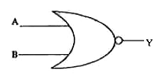
OR gate
XOR gate
NAND gate
NOR gate
The correct Answer is:A
Step by step video & image solution for The logic symbol shown in figure represents by Physics experts to help you in doubts & scoring excellent marks in Class 12 exams.
Updated on:21/07/2023Topper's Solved these Questions
- SEMICONDUCTOR DEVICESBOOK - AAKASH SERIESCHAPTER - SEMICONDUCTOR DEVICESEXERCISE - EXERCISE - III
3 Videos
- SEMICONDUCTOR DEVICESBOOK - AAKASH SERIESCHAPTER - SEMICONDUCTOR DEVICESEXERCISE - EXERCISE - IB
7 Videos
- RAY OPTICSBOOK - AAKASH SERIESCHAPTER - RAY OPTICSEXERCISE - PROBLEMS ( LEVEL-II)
60 Videos
- UNITS AND MEASUREMENTBOOK - AAKASH SERIESCHAPTER - UNITS AND MEASUREMENTEXERCISE - PRACTICE EXERCISE
45 Videos
Similar Questions
Knowledge Check
The I-V characteristics shown in the figure represents
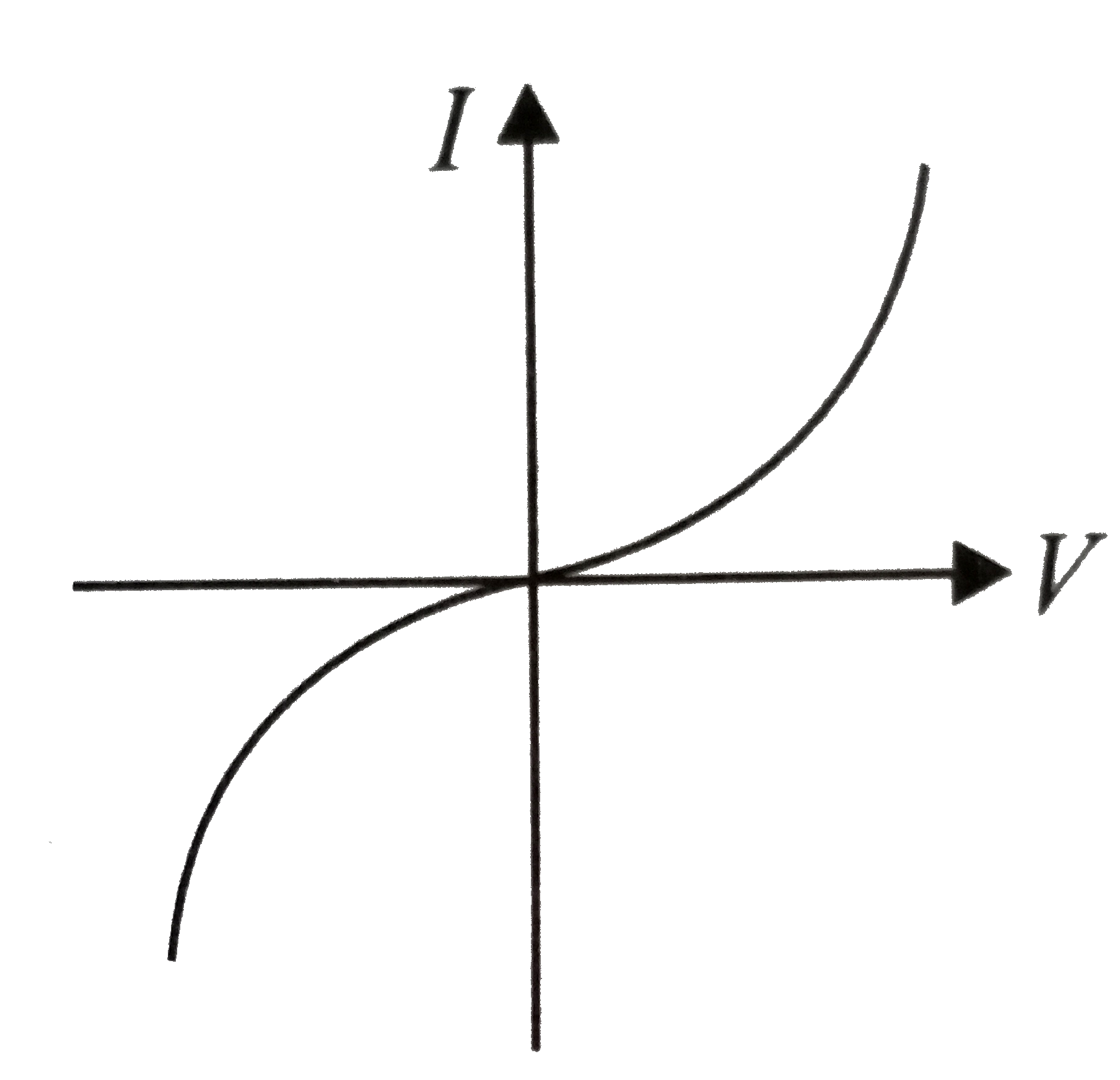 Aohmic conductorsBnon-ohmic conductorsCinsulatorsDsuperconductors
The x-t graph shown in figure represents

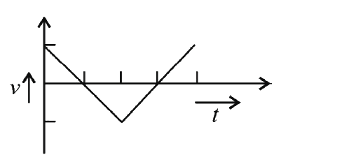
View SolutionThe graph in figure shows the velocity v versus time t for a body. Which of the graphs shown in figure represents the correesponding acceleration versus time graphs ?
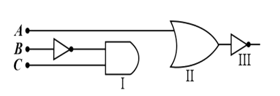
View SolutionThe outpout Y of the logic circuit shown in figure is best represented as
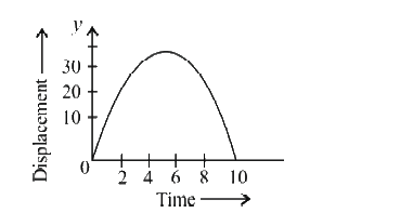
View SolutionThe displacement-time graph of a moving object is shown in figure. Which of the velocity-time graphs shown in figure could represent the motion of the same body ?
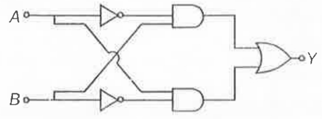
View SolutionThe logic circuit (figure) represents which logic gate?
View SolutionThe logic symbols shown here are logically equivalent to :-
_E01_426_Q01.png)
View SolutionThe symbol of an element represents a molecule of it.
View Solution

