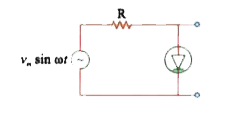
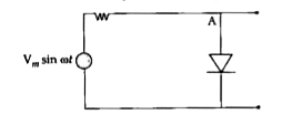
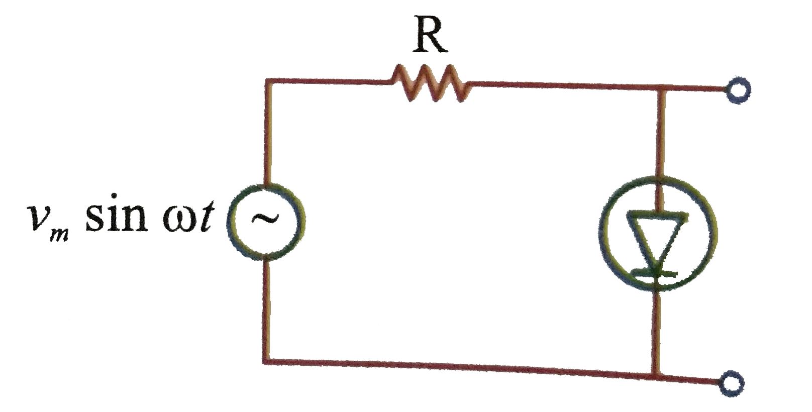
The output of the given circuit in the given figure

A
would be zero at all times
B
would be like a half wave rectifier with positive cycles in output
C
would be like a half wave rectifier with negative cycles in output
D
would be like that of a full wave recitifer
Text Solution
The p-n junction is forward biased during positive half of input ac and its resistance is cloase to zero hence voltage drop across p-n junction is zero the p-n junction is reverse biased during negative half of input ac and its resistance is very high p-n juction with negative cycle in output hence the circuit would be half wave rectifier with negative cycle in output
|
Updated on:21/07/2023
Topper's Solved these Questions
- BOOK - MODERN PUBLICATIONCHAPTER - SEMICONDUCTOR ELECTRONICS METERIALS DEVICES AND SIMPLE CIRCUITS EXERCISE - COMPETION FILE (NCERT EXEMPLAR PROBLEMS :MULTIPLE CHOICE QUESTION TYPE -II)8videos
SEMICONDUCTOR ELECTRONICS METERIALS DEVICES AND SIMPLE CIRCUITS
- BOOK - MODERN PUBLICATIONCHAPTER - SEMICONDUCTOR ELECTRONICS METERIALS DEVICES AND SIMPLE CIRCUITS EXERCISE - CHAPTER PRACTICE TEST FOR BOARD EXAMINATION12videos
SEMICONDUCTOR ELECTRONICS METERIALS DEVICES AND SIMPLE CIRCUITS
- BOOK - MODERN PUBLICATIONCHAPTER - SEMICONDUCTOR ELECTRONICS METERIALS DEVICES AND SIMPLE CIRCUITS EXERCISE - COMPETION FILE (INTEGER TYPE QUESTIONS)10videos
SEMICONDUCTOR ELECTRONICS METERIALS DEVICES AND SIMPLE CIRCUITS
- BOOK - MODERN PUBLICATIONCHAPTER - RAY OPTICS AND OPTICAL INSTRUMENTSEXERCISE - CHAPTER PRACTICE TEST14videos
RAY OPTICS AND OPTICAL INSTRUMENTS
- BOOK - MODERN PUBLICATIONCHAPTER - WAVE OPTICALEXERCISE - CHAPTER PRACTICE TEST7videos
WAVE OPTICAL
Similar Questions
Knowledge Check
- Question 1 - Select One
The output of the given circuit in Fig.
 Awould be zero at all timesBwould be like a half wave rectifier with positive cycles in outputCwould be like a half wave rectifier with negative cycles in outputDwould be like that of a full wave rectifier
 - Question 2 - Select One
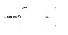
The output of the given circuit in Fig.
 Awould be zero at all timesBwould be like a half-wave recifier with positive cycles in outputCwould be like a half-wave rectifer with negative cycles in outputDwould be like that of a full-wave rectifier.
 - Question 3 - Select One
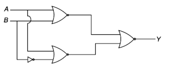
The output for the given, circuit is
 A(A+B)⋅¯¯¯BB(A⋅B)⋅¯¯¯BC(A+B)⋅BD(A⋅B)⋅B

 .
.