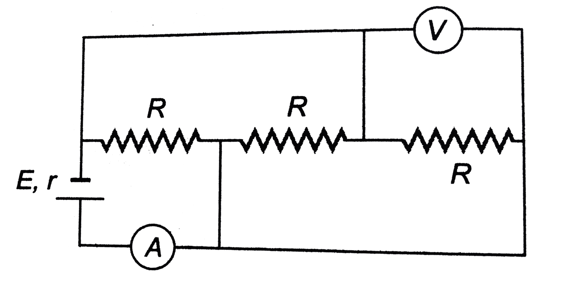
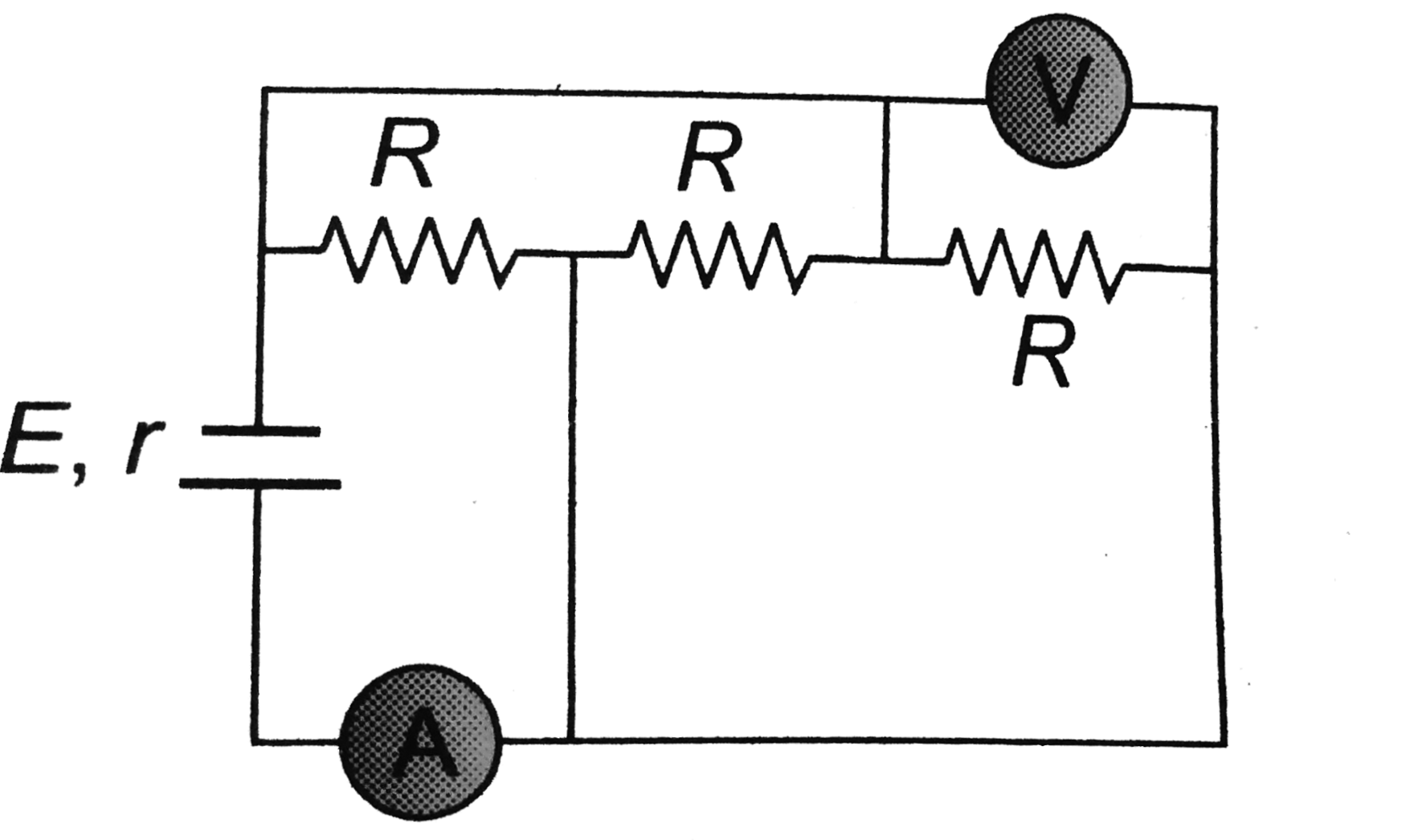
the resistance of the ammeter and the voltmeter are respectively . What are the readings of the ammeter and the voltmeter ?

In the circuit , currents flowing in the three loops have been shown as (clockwise ).
From the second law of Kirchhofff we get , for the first loop ,
or ,
for the second loop,
or ,
for the third lopp ,
or ,
From (1) and (3)
Substituting these values in equation (2) we get ,
or ,
or ,
Reading of voltemter
and reading of ammeter
Topper's Solved these Questions
- KIRCHHOFF'S LAWS AND ELECTRICAL MEASUREMENT BOOK - CHHAYA PUBLICATIONCHAPTER - KIRCHHOFF'S LAWS AND ELECTRICAL MEASUREMENT EXERCISE - Section Related Questions
14 Videos
- KIRCHHOFF'S LAWS AND ELECTRICAL MEASUREMENT BOOK - CHHAYA PUBLICATIONCHAPTER - KIRCHHOFF'S LAWS AND ELECTRICAL MEASUREMENT EXERCISE - HIGHER ORDER THINKING SKILL (HOTS) QUESTIONS
20 Videos
- ELEMENTARY PHENOMENA OF ELECTROSTATICS BOOK - CHHAYA PUBLICATIONCHAPTER - ELEMENTARY PHENOMENA OF ELECTROSTATICS EXERCISE - EXAMINATION ARCHIVE
2 Videos
- LIGHT WAVE AND INTERFERENCE OF LIGHT BOOK - CHHAYA PUBLICATIONCHAPTER - LIGHT WAVE AND INTERFERENCE OF LIGHT EXERCISE - CBSE SCANNER
15 Videos
Similar Questions
Knowledge Check
In the circuit shown in figure ammeter and voltmeter are ideal. If E=4V,R=9Ω and r=1Ω then readings of ammeter and voltmeter are
 A1A,3VB2A,3VC3A,4VD4A,4V
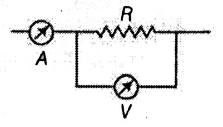
For the adjoining circuit diagram, the readings of ammeter and voltmeter are 2A and 120 V respectively. If the value of R is 75Ω, then the voltmeter resistance will be
 A100ΩB150ΩC300ΩD75Ω
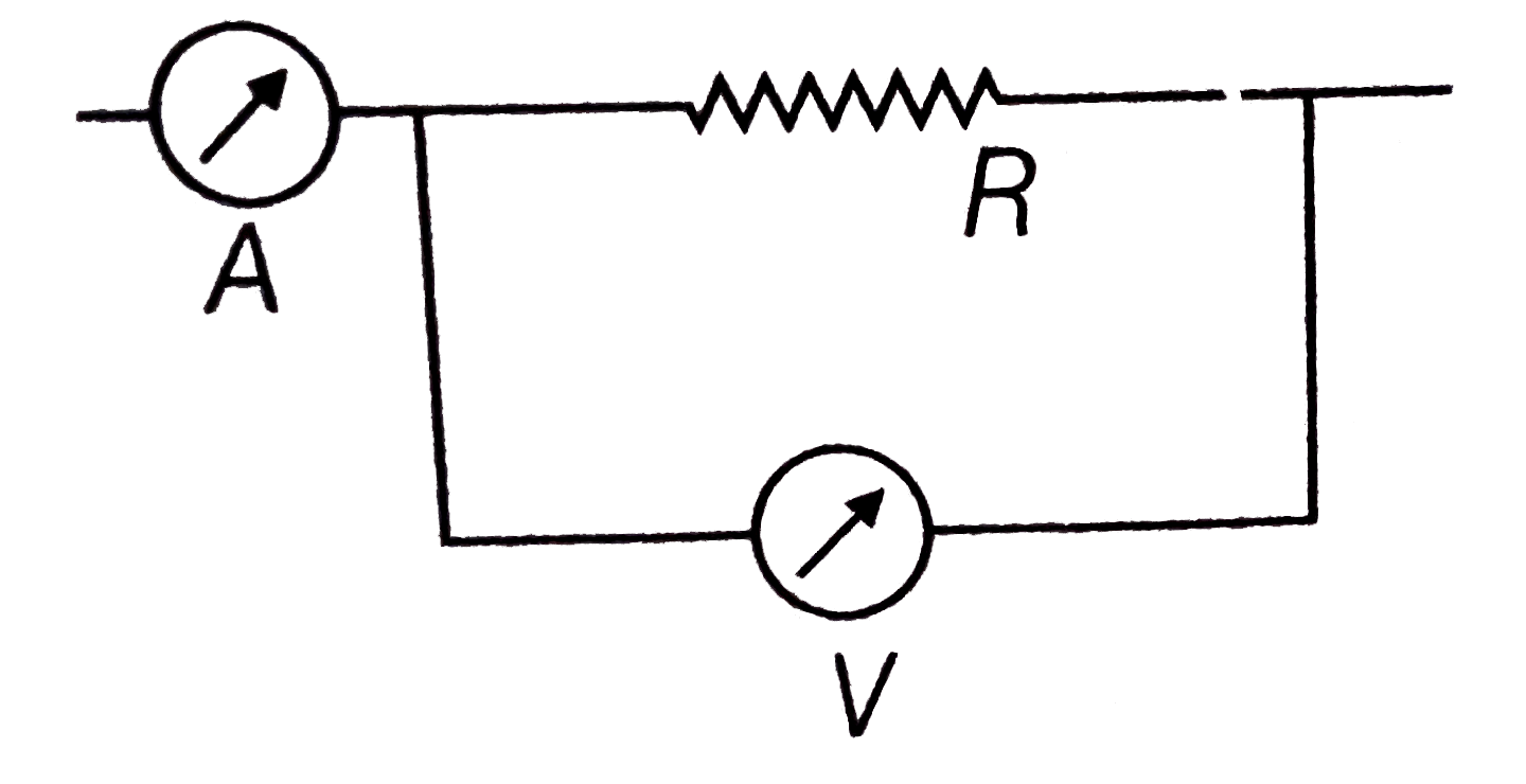
In the adjoining circuit diagram, the readings of ammeter and voltmeter are 2 A and 120 V, respectively. If the value of R is 75Ω, then the voltmeter resistance will be
 A100ΩB150ΩC300ΩD75Ω
In the adjoining circuit diagram, the readings of ammeter and voltmeter are 2 A and 120 V, respectively. If the value of R is 75Ω, then the voltmeter resistance will be

View SolutionResistance value of an unknown resistor is calculated using the formula R=VI where V and I be the readings of the voltmeter and the ammeter respectively. Consider the circuits below. The internal resistances of the voltmeter and the ammeter (RvandRGrespectively ) are finite and non zero.
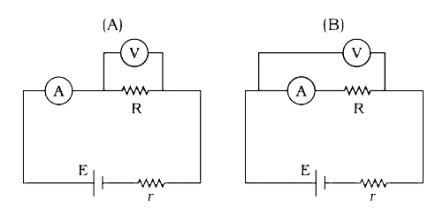
Let RvandRG be the calculated values in the two cases A and B respectively.
If the resistance of voltmeter is Rv=1kΩ and that of ammeter is RG=1Ω the magnitude of the percentage error in the measurement of R (the value of R is nearly 10Ω ) is:
View SolutionIn the circuit shown,the coil resistance of the ammeter is 1Ω while that of the voltmeter is 20Ω .The main branch current is 1920 A.The reading of voltmeter in volt is
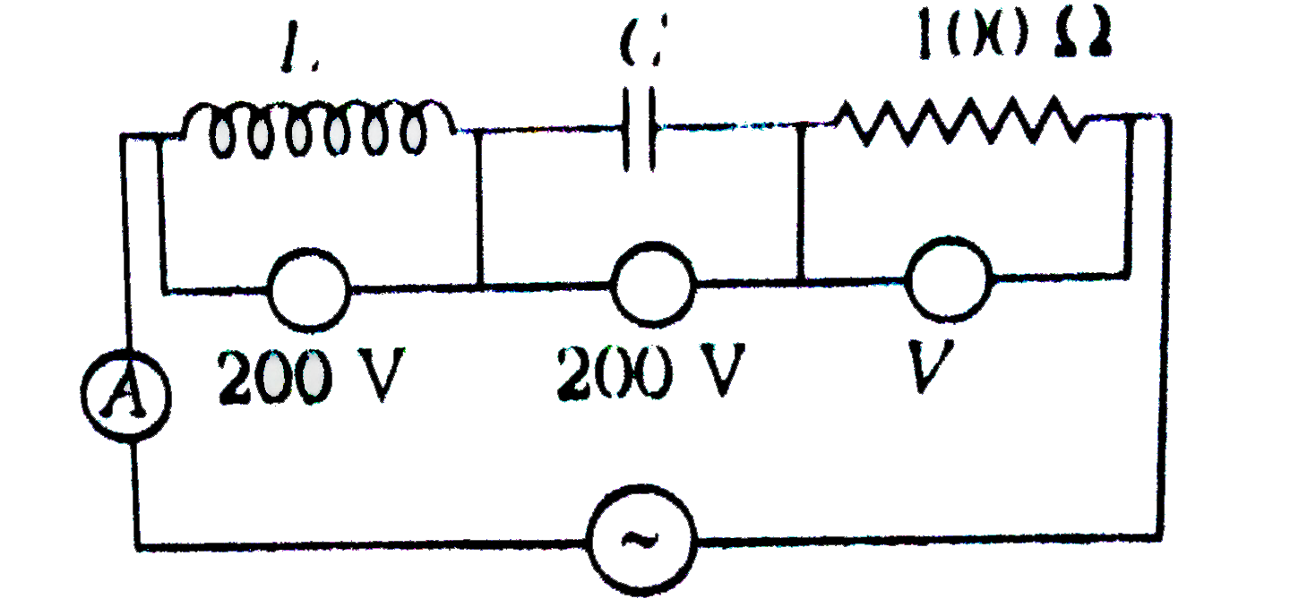
View SolutionThe reading of ammeter and voltmeter in the following circuit are respectively
View SolutionIn the circuit shwon in figure, ammeter and voltmeter are ideal. E=4V,R=15Ω and r=1Ω, then reading of ammter (in A) and voltmeter (in V) respectively are:
View Solution
