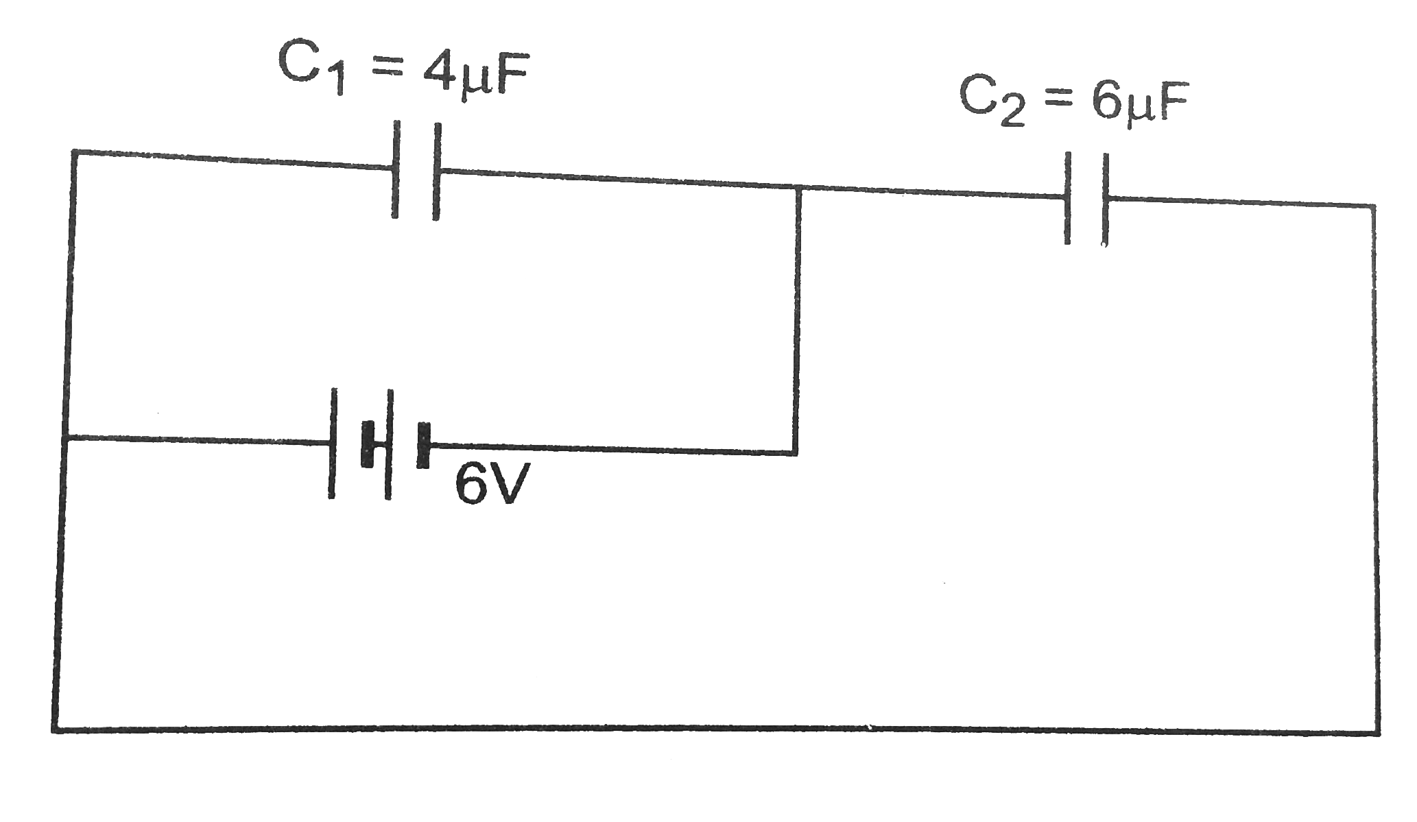
Two capacitors C1andC2 are connected in a circuit as shown in figure. The potential difference (VA−VB) is
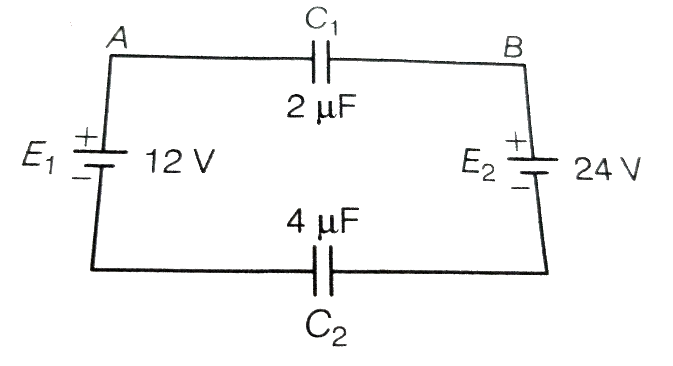
8 V
−8V
12 V
−12V
The correct Answer is:B
Consider the diagram below,
12−VA+VB−24+VD−VC=0
⇒ VA−VB=12+VD−VC−24
=−12+(Q4μF)
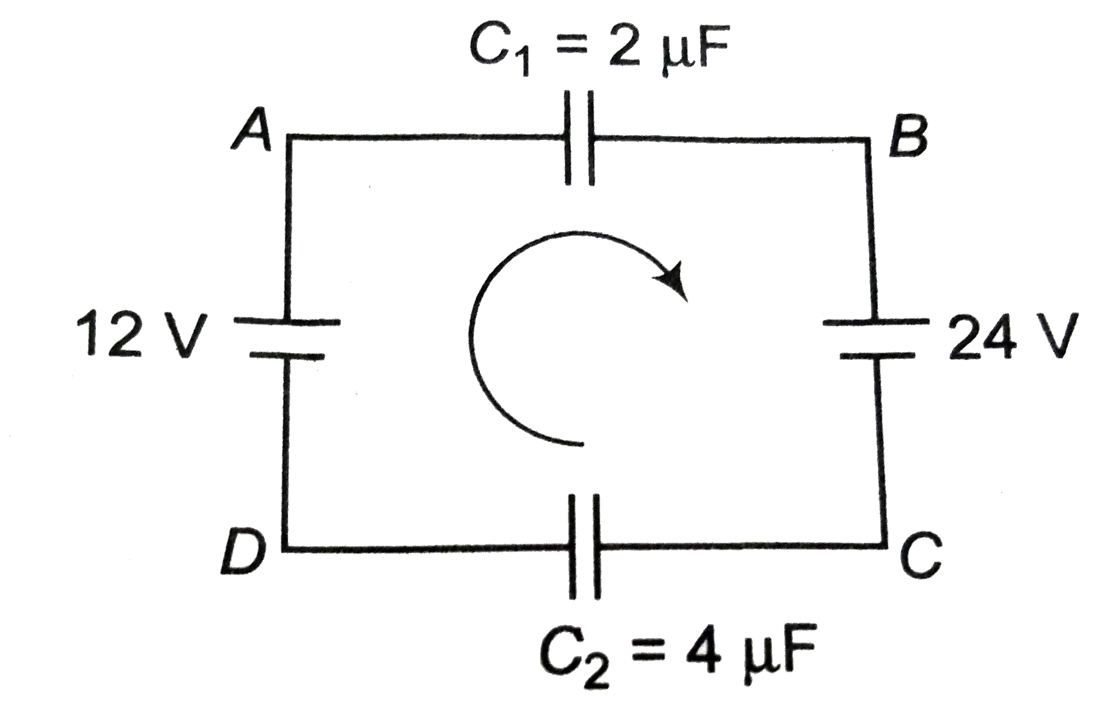
⇒ −Q2μF=−12+Q4μF
⇒ Q[12+14]=12μC
⇒ Q=12×86μC=16μC
⇒ VA−VB=−QC1=−16μC2μF=−8V
Topper's Solved these Questions
- ELECTROSTATICSBOOK - MHTCET PREVIOUS YEAR PAPERS AND PRACTICE PAPERSCHAPTER - ELECTROSTATICSEXERCISE - PRACTICE EXERCISE (Exercise 2 (MISCELLANEOUS PROBLEMS))
47 Videos
- ELECTROSTATICSBOOK - MHTCET PREVIOUS YEAR PAPERS AND PRACTICE PAPERSCHAPTER - ELECTROSTATICSEXERCISE - MHT CET Corner
29 Videos
- ELECTROSTATICSBOOK - MHTCET PREVIOUS YEAR PAPERS AND PRACTICE PAPERSCHAPTER - ELECTROSTATICSEXERCISE - MHT CET Corner
29 Videos
- ELECTRONS AND PROTONSBOOK - MHTCET PREVIOUS YEAR PAPERS AND PRACTICE PAPERSCHAPTER - ELECTRONS AND PROTONSEXERCISE - MHT CET CORNER
19 Videos
- FORCEBOOK - MHTCET PREVIOUS YEAR PAPERS AND PRACTICE PAPERSCHAPTER - FORCEEXERCISE - Exercise 2 (Miscellaneous Problems)
19 Videos
Similar Questions
Four capacitors C1,C2,C3 and C4 are connected as shown in figure.If potential difference between points A and B is zero, then
View SolutionThree capacitors C1,C2 and C3 are connected as shown in, The potentials of P,Q, and R are V1,V2, and V3, respectively. Find the potential V0 at the functionO.
 .
.
View Solution
Knowledge Check
A circuit shown in the figure consists of a battery of emf 10V and two capacitance C1 and C2 of capacitances 1.0μF and 2.0μF respectively. The potential difference VA−VB is 5V
 ACharge on capacitor C1 is equal to charge on capacitor C2BVoltage across capacitor C1 is 5V.CVoltage across capacitor C2 is 10VDEnegry stored in capacitor C1 is two times the enegry stored in capacitor C2.
Three uncharged capacitors of capacities C1,C2 and C3 are connected as shown in the figure to one another and the potentials V1,V2 and V3 respectively. Then the potential at O will be
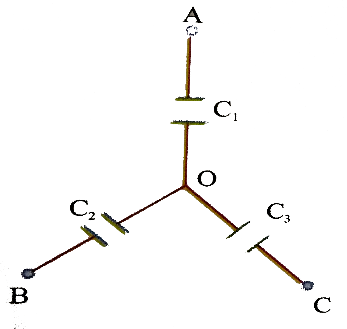 .AV1C1+V2C2+V3C3C1+C2+C3BV1+V2+V3C1+C2+C3CV1(V2+V3)C1(C2+C3)DV1V2V3C1C2C3
Two condensers C1 and C2 in a circuit are jhioned as shown in . The potential fo point A is V1 and that of B is V2 . The potential of point D will be
 A12(V1+V2)BC1V2+C2V1C1+C2CC1V1+C2V2C1+C2DC2V1−C1V2C1+C2
Three capacitors C1,C2 and C3 are connected as shown in, The potentials of P,Q, and R are V1,V2, and V3, respectively. Find the potential V0 at the functionO.
 .
.
View SolutionA circuit shown in the figure consists of a battery of emf 10V and two capacitance C1 and C2 of capacitances 1.0μF and 2.0μF respectively. The potential difference VA−VB is 5V

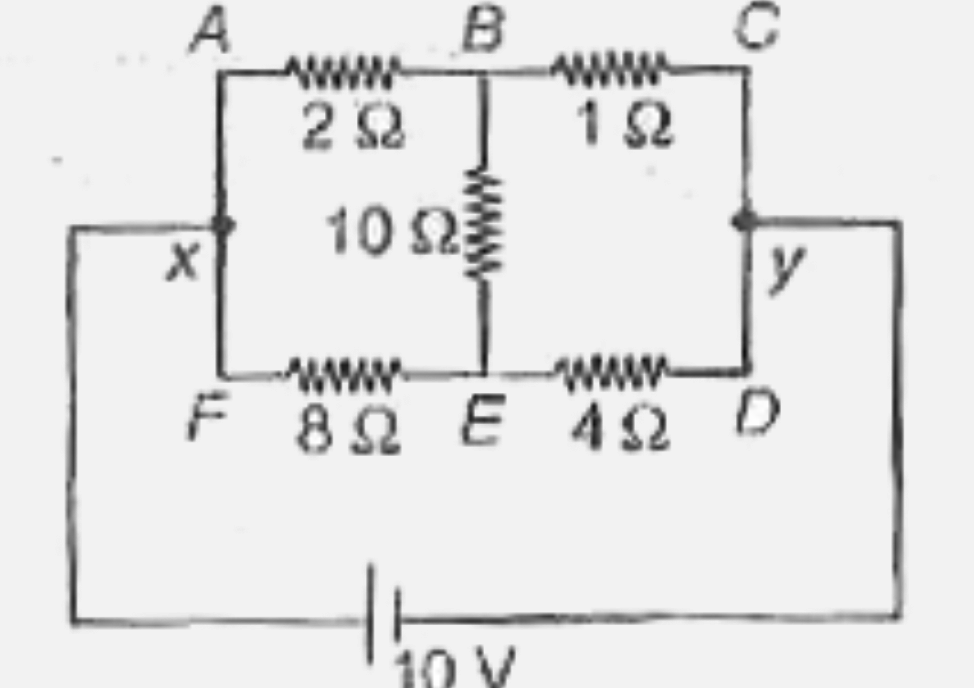
View SolutionA combination of five resistors are connected to a cell of emf 10 V as shown in figure. The potential difference VB−VE will be .
View SolutionTwo capacitors C1 and C2 are connected to a battery of 6V as shown in Fig. Find the charge on each capacitor.
View SolutionTwo condensers C1 and C2 in a circuit are jhioned as shown in . The potential fo point A is V1 and that of B is V2 . The potential of point D will be

View Solution
