Various parts on the outer surface of an electric cell are labelled as I, II, III, and IV respectively in figure (a). In figure (b), an incomplete circuit is shown. M and N are the free ends of this circuit.
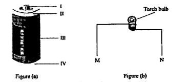
To make the bulb glow, free ends M and N of the circuit should be respectively connected to
I and II
II and III
III and IV
IV and I
Step by step video & image solution for Various parts on the outer surface of an electric cell are labelled as I, II, III, and IV respectively in figure (a). In figure (b), an incomplete circuit is shown. M and N are the free ends of this circuit. To make the bulb glow, free ends M and N of the circuit should be respectively connected to by Physics experts to help you in doubts & scoring excellent marks in Class 7 exams.
Topper's Solved these Questions
- BOOK - BEIITIANSCHAPTER - ELECTRIC CURRENT AND ITS EFFECTSEXERCISE - IIT JEE WORKSHEET (I. Single Correct Answer Type)19videos
ELECTRIC CURRENT AND ITS EFFECTS
- BOOK - BEIITIANSCHAPTER - ELECTRIC CURRENT AND ITS EFFECTSEXERCISE - IIT JEE WORKSHEET (II. Multiple Correct Answer Type)1videos
ELECTRIC CURRENT AND ITS EFFECTS
- BOOK - BEIITIANSCHAPTER - ELECTRIC CURRENT AND ITS EFFECTSEXERCISE - SUMMATIVE WORKSHEET23videos
ELECTRIC CURRENT AND ITS EFFECTS
- BOOK - BEIITIANSCHAPTER - HEATEXERCISE - IIT JEE Worksheet (V. Matrix Matching)4videos
HEAT
Similar Questions
Four parts of an electric iron are labelled as I, II, III, and IV (as shown in the given figure).

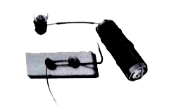
The element of the given electric iron is labelled asView SolutionComplete the drawing shown in Fig 12.14 to indicate where the free ends of the two wires should be joined to make the bulb glow.
 View Solution
Knowledge Check
- Question 1 - Select One
There are N cells in the circuit of figure. The emf and internal resistance of each cell is E and r respectively. The points A and B in the circuit divide the circuit into n and (N−n)cells. The current in the circuit is
AE/rBnE/rCNE/nrDzero - Question 2 - Select One
Two identical capacitors A and B are charged to the same potential V and are connected in two circuits at t=0 as shown in figure. The charge of the capacitors at a time t=CR are respectively-
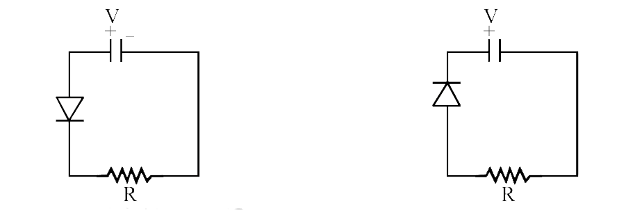 AVC, VCBVC/e,VCCVC,VC/eDVC/e,VC/e
 - Question 3 - Select One or More
Two capacitors of 2μF and 3μF are charged to 150V and 120V, respectively. The plates of capacitor are connected as shown in the figure. An uncharged capacitor of capacity 1.5μF falls to the free end of the wire. Then
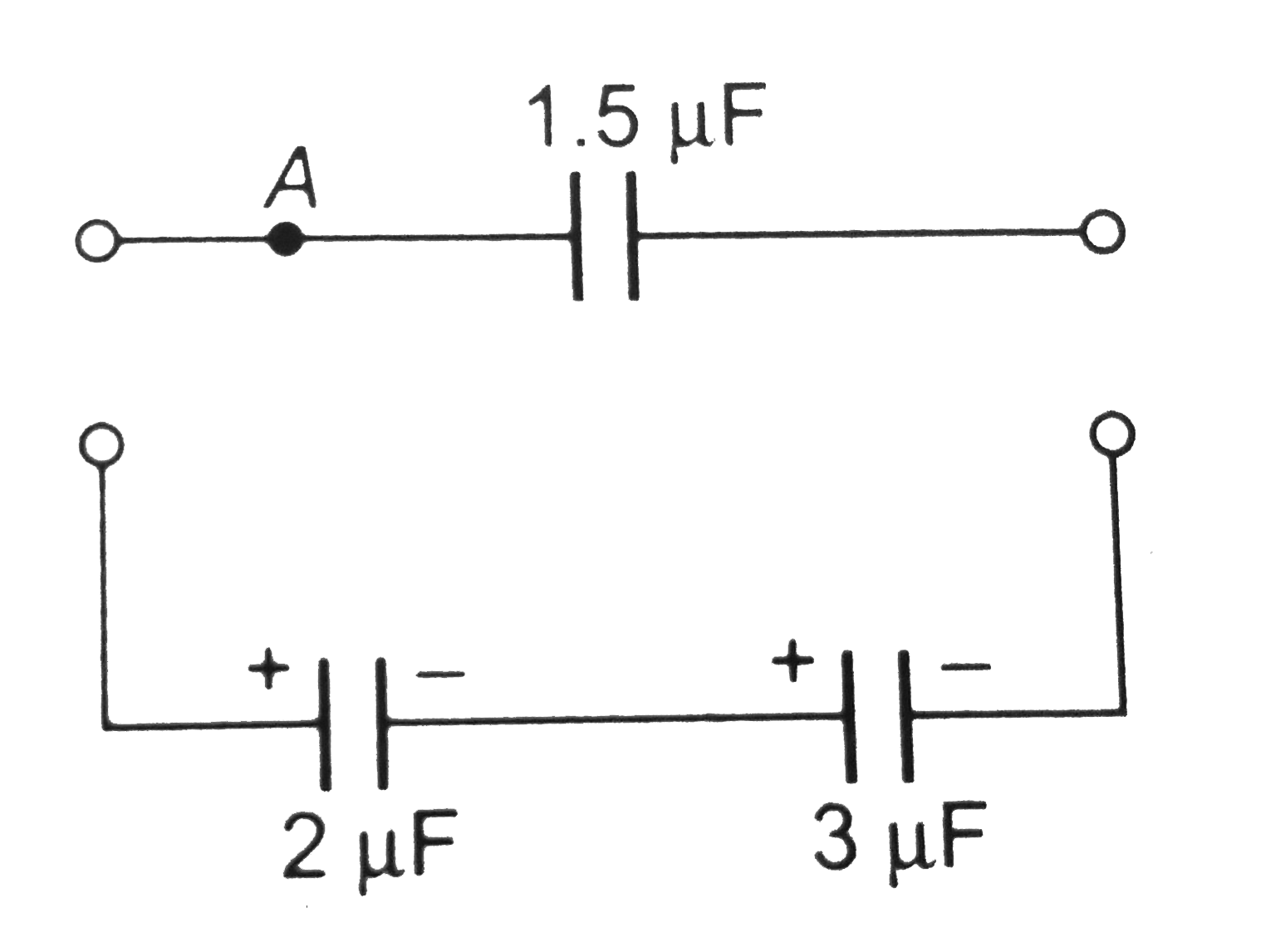 Achargeg on 1.5μF capacitor is 180μFBcharge on 2μFcapacitor is 120μFCpositive chasrge flows through A from right to leftDpositive charge flows through A from left to right
The schematic diagram of an open circuit is shown in the given figure.
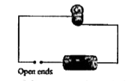
Opa ends Which of the following objects is inserted tightly in the gap to make the bulb glow?View SolutionTwo identical capacitors A and B are charged to the same potential V and are connected in two circuits at t = 0 as shown in figure. The charge of the capacitors at a time t = CR are respectively -
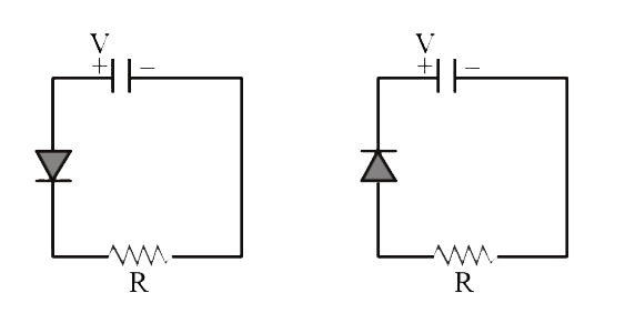 View Solution
The given figure represents dour circuit arrangements, I, II, III and IV. Each circuit consists of an electric cell and a torch bulb.
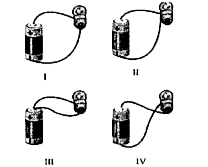
The bulb may glow in the circuit arrangements labelled asView SolutionDifferent arrangements of an electric bulb with an electric cell are shown in the given figure. The arrangements are labelled as M, N, S, and T respectively.
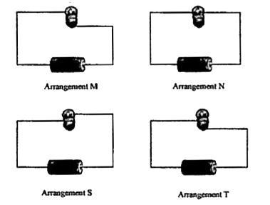
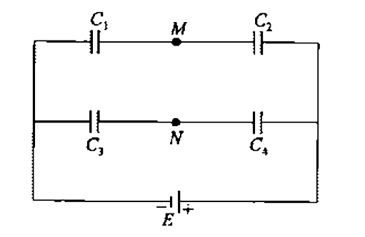
The bulb will glow inView SolutionIn the circuit shown in figure four capacitors are connected to a battery. Determine the potential difference VM−VN between· points M and N of the circuit. Find the conditions under which it is equal to zero.
 View Solution

