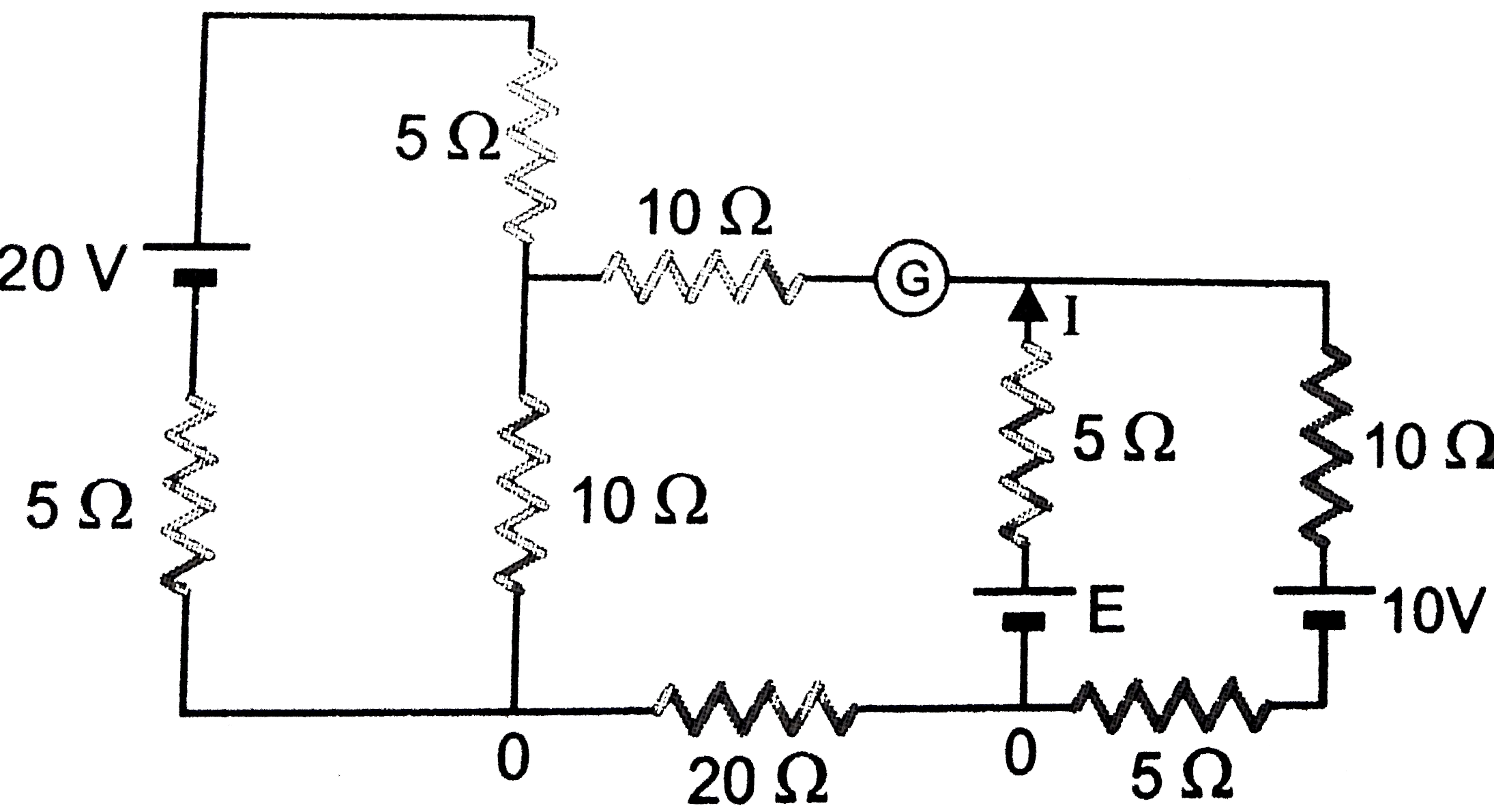
What would be the value of E so that the galvanometer G circuit shown on deflection
5V
10V
15V
20V
The correct Answer is:B
Refer G will show no deffection if point C and l are as the same potential
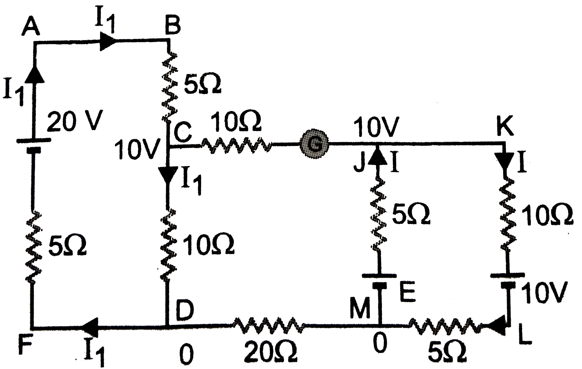
In circuit ABCDEF current, I1=205+10+5=1A
pot diff between C and D=I1×10=1×10=10V
Since point D is a zero potential therefore pot of point C=10V
Hence potential of point J potential point C=10V
Since point M is at zero potential pot diff between EandJ=(E−10)V
In circuit KLMJK current 1 is
1=E−105+10+5=E−1020
pot diff across 5Ω between point EandJ is
E−10=(E−1020)5=E−104
or 4E−40=E−10or3E=30orE=10V
Topper's Solved these Questions
- BOOK - PRADEEPCHAPTER - CURRENT ELECTRICITYEXERCISE - Jee (main and advance)4videos
CURRENT ELECTRICITY
- BOOK - PRADEEPCHAPTER - CURRENT ELECTRICITYEXERCISE - Interger Type2videos
CURRENT ELECTRICITY
- BOOK - PRADEEPCHAPTER - CURRENT ELECTRICITYEXERCISE - Value based2videos
CURRENT ELECTRICITY
- BOOK - PRADEEPCHAPTER - COMMUNICATION SYSTEMSEXERCISE - MODEL TEST PAPER-29videos
COMMUNICATION SYSTEMS
- BOOK - PRADEEPCHAPTER - DUAL NATURE OF RADIATION AND MATTEREXERCISE - Exercise191videos
DUAL NATURE OF RADIATION AND MATTER
Similar Questions
Knowledge Check
- Question 1 - Select One
What would be the value of E so that the galvanometer G circuit shown on deflection
 A5VB10VC15VD20V
 - Question 2 - Select One
In the given circuit, the galvanmeter G will show zero deflection if
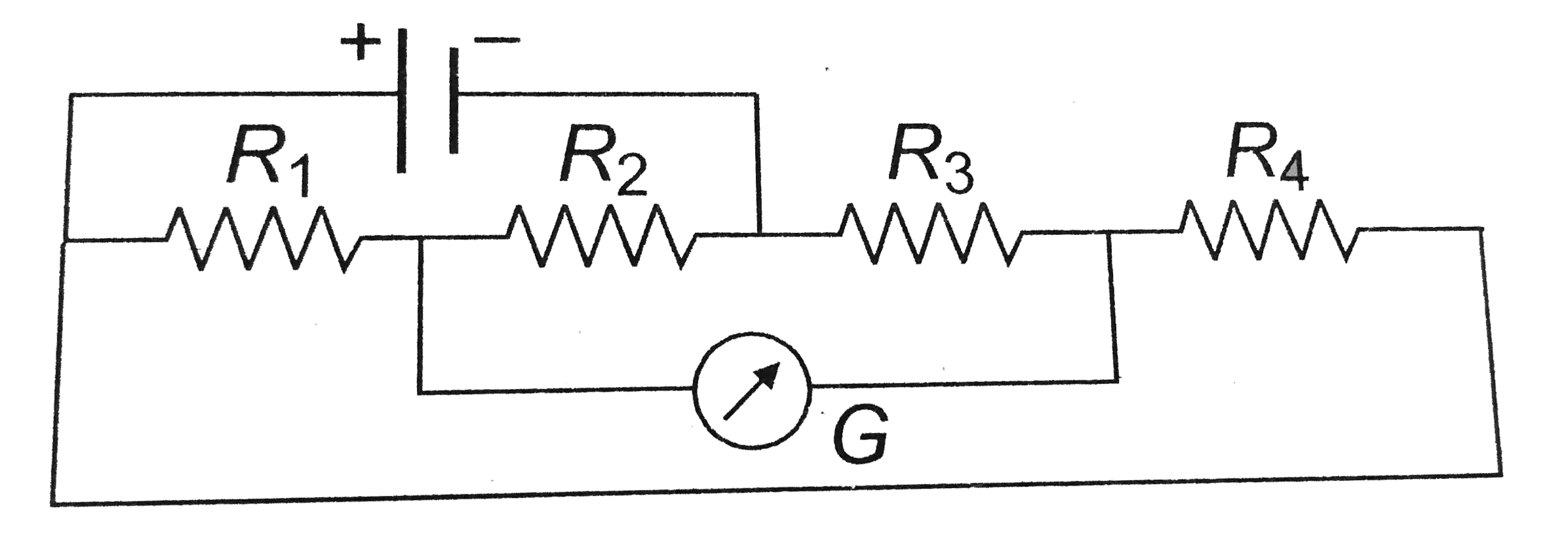 AR1R2=R3R4BR1R3=R2R4CR1R4=R2R3Dgalvanometer can't have zero current for any relation between the resistances
 - Question 3 - Select One
What should be the value of resistance R in the circuit shown in figure so that the electric bulb consumes the rated power?
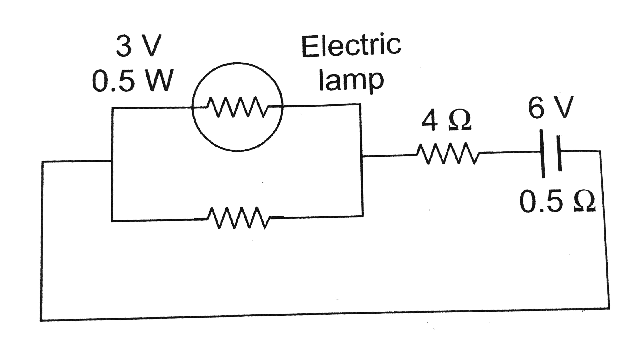 A4.5ΩB6ΩC12ΩDNone fo these
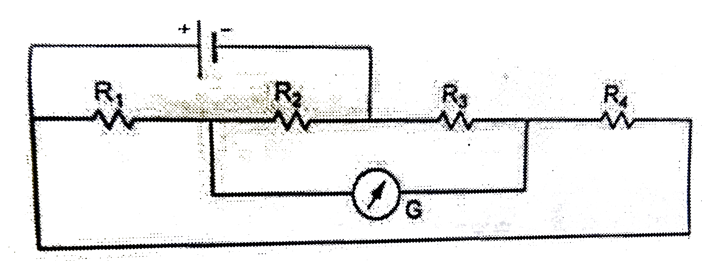
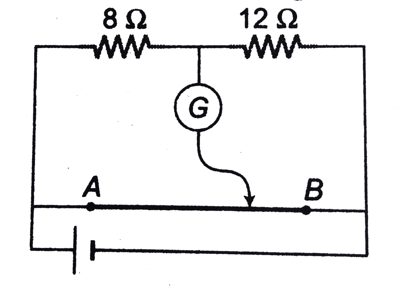
In the given circuit , the galvometer G will show zero deflection ifView SolutionThe potentiometer wire AB shown in figure is 40 cm long. Where should the free end of the galvanometer be connected on AB so that the galvanometer may show zero deflection?
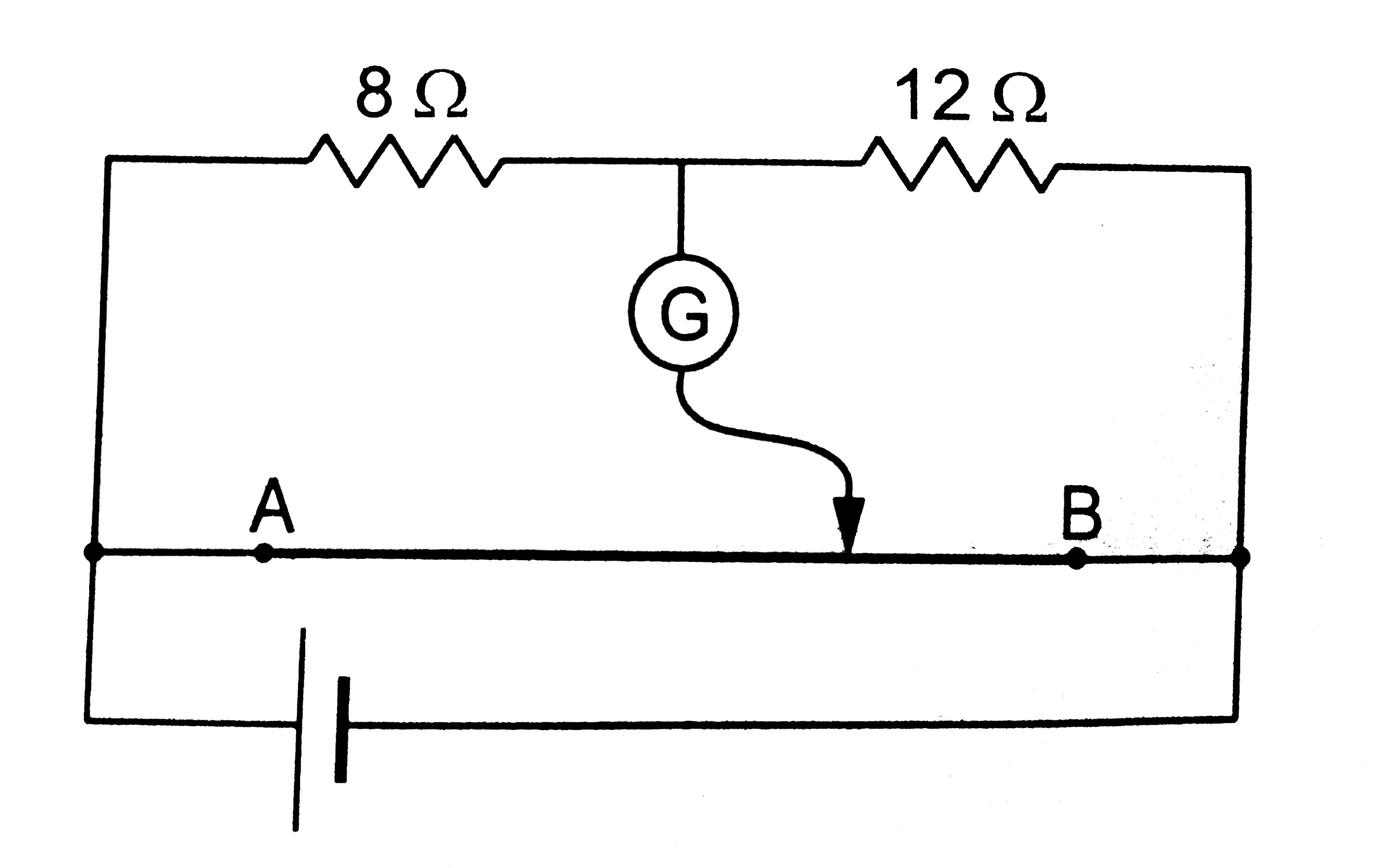 View Solution
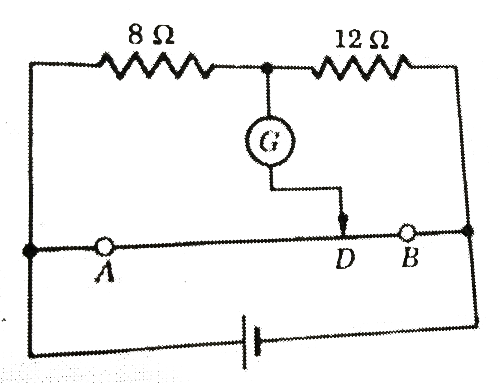
The potentiometer wire AB shown in figure. Is 40 cm long. Where should the free end of the galvanometer be connected on AB so that the galvanometer may show zero deflection?View Solution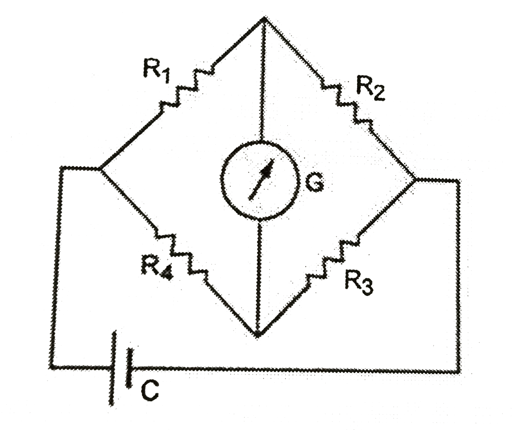
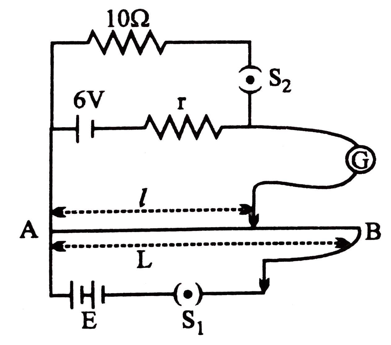
The Wheatstone bridge shown in the above figure is balanced. If the positions of the cell C and the galvanometer G are now interchanged, G will show zero deflectionView SolutionIn the arrangement shown in figure when the switch S2 is open, the galvanometer shown no deflection for l=L/2. When the switch S2 is closed, the galvanometer shown no deflection for l=5L/12. The internal resistance (r) of 6V cell, and the emf E of the other battery are respectively
 View Solution


