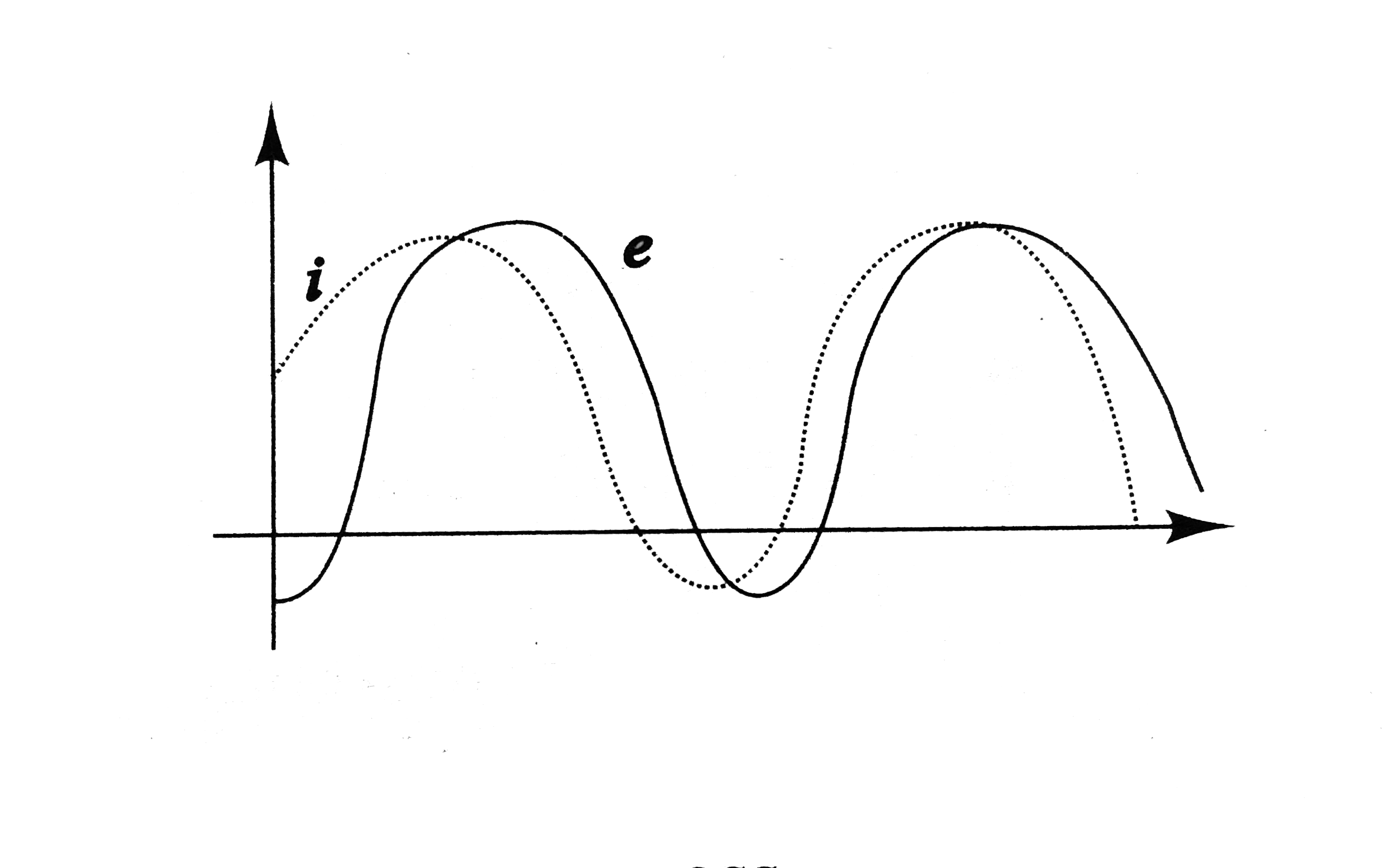
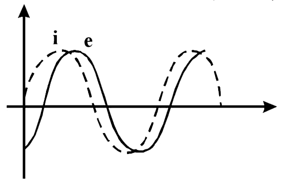
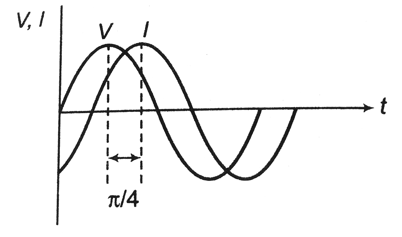
When an ac source of voltage V=V0 sin 100t is connected across a circuit, the phase difference between the voltage V and current I in the circuit is observed to be π/4 , as shown in figure. If the circuit consists possibly only of RC or LR or LC in series, find possible values of two elements.

R=1kΩ,C=10μF
R=1kΩ,C=1μF
R=1kΩ,L=10mH
R=10kΩ,L=10mH
The correct Answer is:A
Figure given in the question shows that current I leads the voltage V by a phase angle π/4 . Therefore , the circuit can be RC circuit alone .
tanϕ=XCR=1ωCR⇒tanπ4=1ωCR⇒1=1ωCR ....(i)
From V=V0sin100t, we get ω=100rads−1
∴CR=1ω=1100
When R=1kΩ=103Ω,C=1105=10−5F=10μF
Topper's Solved these Questions
- ELECTROMAGNETIC INDUCTION AND ALTERNATING CURRENTSBOOK - MTG GUIDECHAPTER - ELECTROMAGNETIC INDUCTION AND ALTERNATING CURRENTSEXERCISE - NEET CAFE TOPICWISE PRATICE QUESTIONS (SERIES LR AND CR CIRCUITS)
1 Videos
- ELECTROMAGNETIC INDUCTION AND ALTERNATING CURRENTSBOOK - MTG GUIDECHAPTER - ELECTROMAGNETIC INDUCTION AND ALTERNATING CURRENTSEXERCISE - NEET CAFE TOPICWISE PRATICE QUESTIONS (POWER IN AC CIRCUITS)
13 Videos
- ELECTROMAGNETIC INDUCTION AND ALTERNATING CURRENTSBOOK - MTG GUIDECHAPTER - ELECTROMAGNETIC INDUCTION AND ALTERNATING CURRENTSEXERCISE - NEET CAFE TOPICWISE PRATICE QUESTIONS (AC CIRCUITS CONTAINING RESISTOR, INDUCTOR OR CAPACITOR)
3 Videos
- DUAL NATURE OF MATTER AND RADIATION BOOK - MTG GUIDECHAPTER - DUAL NATURE OF MATTER AND RADIATION EXERCISE - AIPMT/ NEET MCQs
30 Videos
- ELECTROMAGNETIC WAVESBOOK - MTG GUIDECHAPTER - ELECTROMAGNETIC WAVESEXERCISE - AIPMT/NEET(MCQs)
15 Videos
Similar Questions
When an ac source of emf e=E_(0)sin(100t) is connected across a circuit,the phase difference between emf e and current i in the circuit is observed to be pi/4 as shown in figure.If the circuit consists possibly only of R-C or R-C or L-R series,find the relationship between the two elements.
View SolutionWhen an ac source of emfe=E0sin(100t) is connected across a circuit, the phase difference between emf e and currnet I in the circuit is observed to be (π)/(4) as shown in fig. If the circuit consists possibly only of R-C or R-C of L-R series, find the relationship find the relationship between the two elements.

View Solution
Knowledge Check
When an AC source of emfe=E0sin(100t) is connected across a circuit i in the circuit, the phase difference between the emf e and the current i in the circuit is observed to be (π/4), as shown in the diagram. If the circuit consists possibly only of R-C or R-L or L-C in series, find the relationship between the two elements
 AR=1kΩ,C=10μFBR=1kΩ,C=1μFCR=1kΩ,L=10μFDR=1kΩ,L=1μF
When an ac source of emfe=E0sin(100t) is connected across a circuit, the phase difference between emf e and currnet I in the circuit is observed to be (π)/(4) as shown in fig. If the circuit consists possibly only of R-C or R-C of L-R series, find the relationship find the relationship between the two elements.
 AR=1kΩ,C=10(μ)FBR=1kΩ,C=1(μ)FCR=1kΩ,L=10(μ)FDR=1kΩ,L=1(μ)F
When an ac source of emfe=E0sin(100t) is connected across a circuit, the phase difference between emf e and currnet I in the circuit is observed to be (π)/(4) as shown in fig. If the circuit consists possibly only of R-C or R-C of L-R series, find the relationship find the relationship between the two elements.
 AR=1kΩ,C=10μFBR=1kΩ,C=1μFCR=1kΩ,L=10mHDR=10kΩ,L=10mH
An Ac voltage V=V0sin100t is applied to the circuit, the phase difference between current and voltage is found to be π4, then
 .
.
View SolutionAn Ac voltage V=V0sin100t is applied to the circuit, the phase difference between current and voltage is found to be π4, then
 .
.
View SolutionAn Ac voltage V=V0sin100t is applied to the circuit, the phase difference between current and voltage is found to be π4, then
 .
.
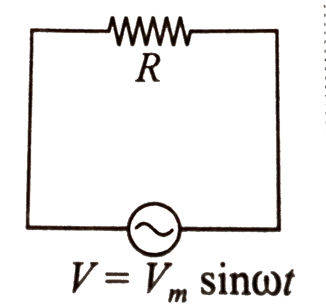
View SolutionAn ac source of voltage V=Vmsinωt is connected across the resistance R as shown in figure. The phase relation between current and voltage for this circuit is

View SolutionAn ac source of voltage V=Vmsinωt is connected across the resistance R as shown in figure. The phase relation between current and voltage for this circuit is

View Solution
