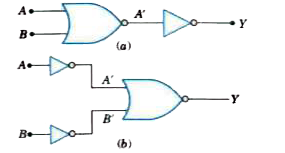
You are given the two circuits as shown in Fig. and . Show that circuit acts as OR gate while the circuit acts as AND gate.
Video Solution
Text Solution
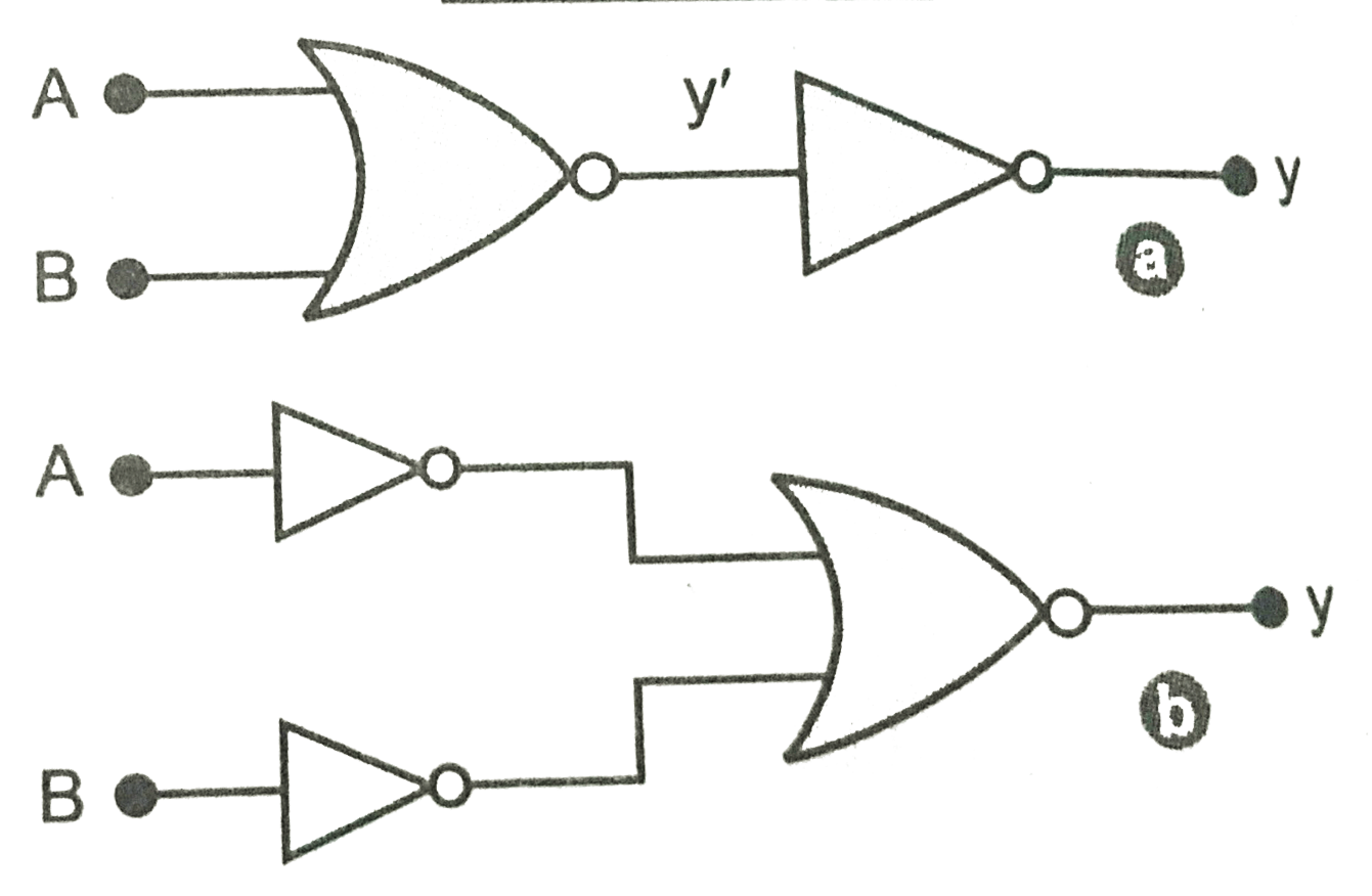
In Fig. , the first gate is a NOR gate and second gate is NOT gate.
The Boolean expression of this combination of gates is
y'=¯¯¯¯¯¯¯¯¯¯¯A+B=¯¯¯A.¯¯¯B
y=¯¯¯¯y′=¯¯¯¯¯¯¯¯¯¯¯¯¯¯baAr.¯¯¯B=¯¯¯¯¯¯¯A+¯¯¯¯¯¯B=A+B
i.e., y=A+B. It is a Boolean Expression of OR gate. Thus, circuit acts as OR gate.
In Fig. the output of two NOT gates is made input to a NOr gate.
The Boolean expression of teh combination of gates is y=¯¯¯¯¯¯¯¯¯¯¯¯¯¯¯A+¯¯¯B=¯¯¯¯¯¯¯A.¯¯¯¯¯¯B=A.B
i.e., y=A.B. It is a Boolean Expression of AND gate. Thus, circuit acts as AND gate.
|
Topper's Solved these Questions
- ELECTRONIC DEVICESBOOK - PRADEEPCHAPTER - ELECTRONIC DEVICESEXERCISE - SAMPLE PROBLEM
2 Videos
- ELECTRONIC DEVICESBOOK - PRADEEPCHAPTER - ELECTRONIC DEVICESEXERCISE - CONCEPTUAL PROBLEMS
1 Videos
- ELECTROMAGNETIC WAVESBOOK - PRADEEPCHAPTER - ELECTROMAGNETIC WAVESEXERCISE - II Focus multiple choice question
5 Videos
- ELECTROSTATICSBOOK - PRADEEPCHAPTER - ELECTROSTATICSEXERCISE - ASSERTION-REASON TYPE QUESTIONS
2 Videos
Similar Questions
Knowledge Check
In the circuit shown in Fig. 7.45,
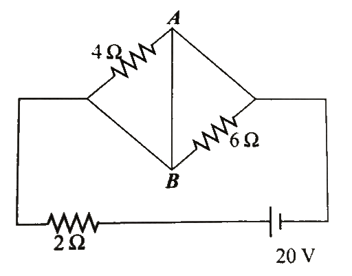 APower supplied by the battery is 200WBcurrent flowing in the circuit is 5ACPotential difference across the 4Ω resistance is equal to the potential difference across the 6Ω resistanceDcurrent in wire AB is zero
In the given circuit (as shown in fig. 5.319).
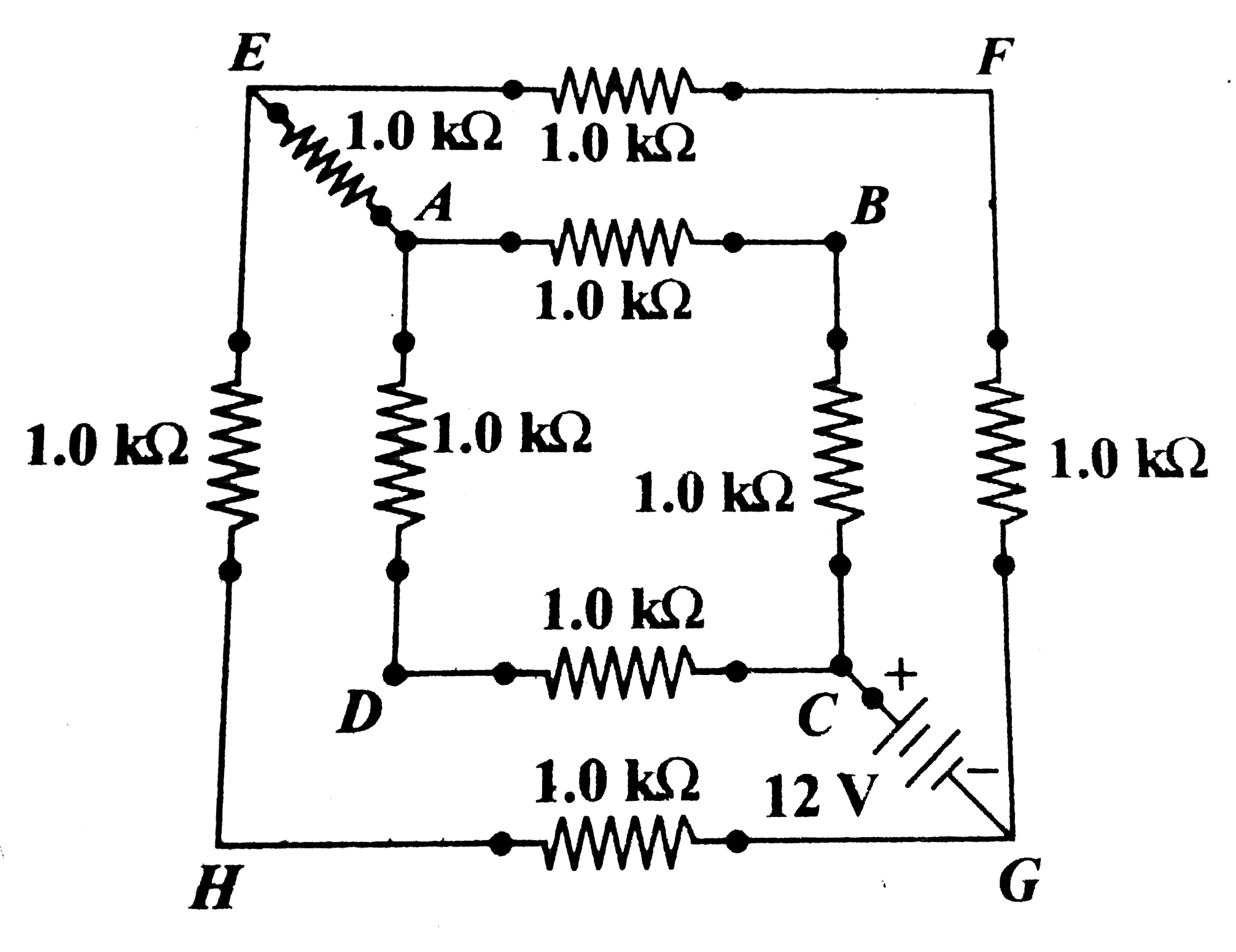 Athe equivalent resistance between C and G is 3KωBthe current provided by the source is 4 mACthe current provided by the source is 8mADvoltage across points G and E is 4V
The circuit shown in the figure acts as
 AOR gateBAND gateCNOT gateDNAND gate
Write the truth table for the circuit shown in fig. Show that it represents a XOR gate.

View SolutionYou are given two circuit as shown in Fig.and . Which consists of NAND gates. Identify the logic operation carried out by the two circuits.

View SolutionThe circuit shown below acts as
View SolutionThe circuit shown below acts as
View SolutionYou are given two circuits as shown in following figure. The logic operation carried out by the two circuit are respectively :-
_E01_415_Q01.png)
View Solution


