Complete Solutions to Experiment 5 of chapter PRACTICAL BASED QUESTIONS of Class 10 book with complete answers and questions
| Class 10 | PHYSICS |
| Chapter | PRACTICAL BASED QUESTIONS |
| VK GLOBAL PUBLICATION | Experiment 5 |
| Number Of Questions | 9 |
| Academic Year | 2023-24 |
The following apparatus is available in a laboratory.
Cell : Adjustable from 0 to 4.5 volt
Resistors : `3Omega` and `6Omega`
Ammeters : `A_(1)` of Range 0 to 3 A, Least count `0.1 A
`A_(2)` of Range 0 to 1 A, Least count `0.05` A
Voltmeters : `V_(1)` of Range 0 to `10 V, Least count `0.5` V
`V_(2)` of Range 0 to 5V, Least count `0.1` V
Find the best combination of voltmeter and ammeter for finding the equivalent resistance of the resistors in series.
View SolutionTo determine the equivalent resistance of two resistors when connected in series, a student arranged the circuit components as shown in the diagram. But he did not succeed to achieve the objective.
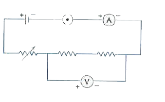
Which mistake has been committed by him in setting up the circuit?
View SolutionWhen a (60W,220V) bulb and a (100 W, 220 V) bulb are connected in series, then which bulb will glow brighter?
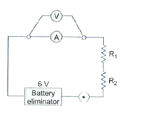
View SolutionIn an experiment to find the equivalent resistance of a series combination of two resistors `R_(1)` and `R_(2),`a student uses the circuit shown here. Will the circuit give the correct reading for current I and voltage V ? Justify your answer.
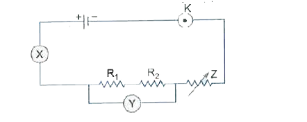
View SolutionThe given circuit diagram shows the experimental arrangement of different circuit components for determination of equivalent resistance of two resistors connected in series. Identify the components X, Y and Z shown in the circuit respectively.
View SolutionA student did the experiment to find the equivalent resistance of two given resistors, `R_(1)` and `R_(2)` first when they are connected in series and next when they are connected in parallel. The two values of the equivalent resistance obtained by him were `R_(s)` and `R_(p)` respectively. Compare `R_(s)` and `R_(p)`.
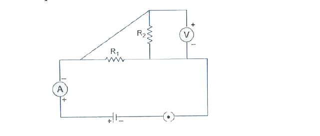
View SolutionWhich of the circuit components in the following circuit diagram are connected in parallel?
View SolutionFind the voltmeter readings for the circuits A and B shown below.
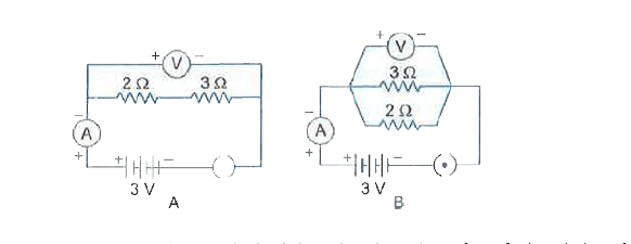
View SolutionThe following apparatus is available in a laboratory.
Cell : Adjustable from 0 to 1.5 volt
Resistor : `4Omega` and `12Omega`
Ammeters : `A_(1)` of range 0 to 3 A, Least count 0.1 A
`A_(2)` of range 0 to 1 A , Least count 0.05 A
Voltmeters : `V_(1)` of range 0 to 10 V, Least count 0.5 V
`V_(2)` of range 0 to 5 v, Least count 0.1 V
Find the best combination of ammeter and voltmeter for finding the equivalent resistance of the resistors.
View Solution
Experiment 5 questions and complete solutions for chapter PRACTICAL BASED QUESTIONS of VK GLOBAL PUBLICATION PHYSICS (HINGLISH) of Class 10