Complete Solutions to Inductor Circuits of chapter ELECTROMAGNETIC INDUCTION of Class 12 book with complete answers and questions
| Class 12 | PHYSICS |
| Chapter | ELECTROMAGNETIC INDUCTION |
| A2Z | Inductor Circuits |
| Number Of Questions | 31 |
| Academic Year | 2023-24 |
The network shown in the figure is a part of complete circuit. What is the potential difference `V_B-V_A` when the current `I` is `5 A` and is decreasing at a rate of `10^3A//s`?

View SolutionIn an `AC` sub circuit, the resistance `R=0.2Omega`. At a certain instant `(V_(A-V_(B))=0.5` volt, `I=0.5 amp` and `(DeltaI//Deltat)=8A//s`. Find the inductance of the coil:

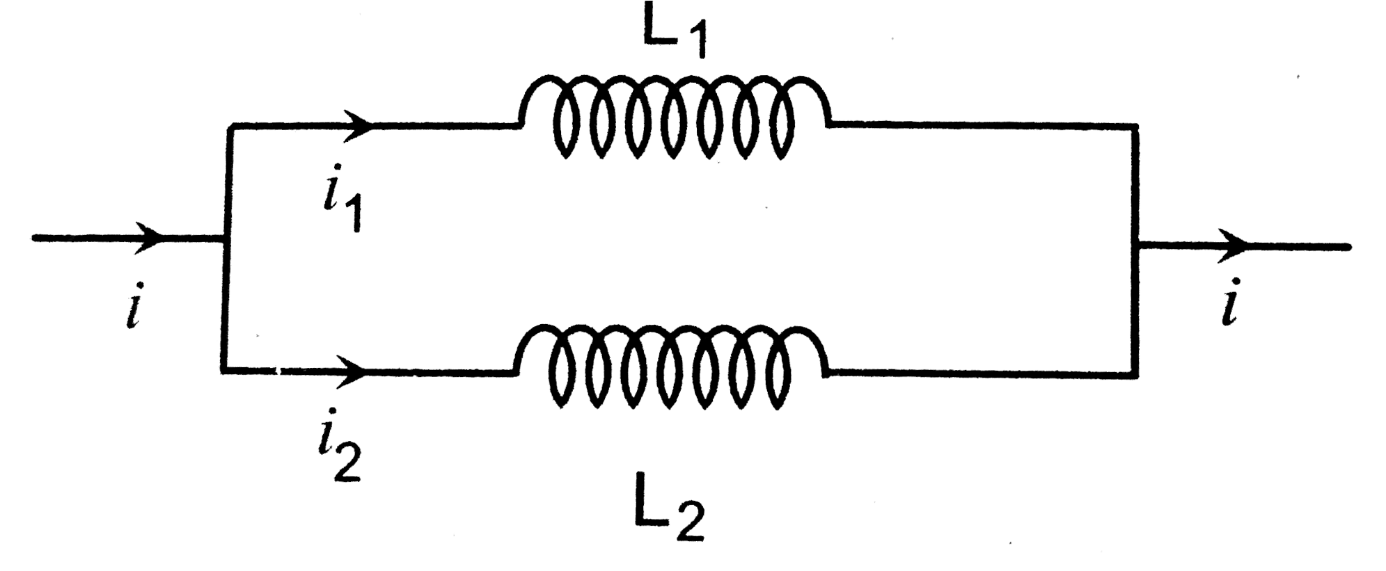
View SolutionTwo inductors `L_(1)` and `L_(2)` are connected in parallel and a time varying current flows as shown.
the ratio of current `i_(1)//i_(2)`
View SolutionAn ideal coil of `10` henry is joined in series with a resistance of `5` ohm and a battery of `5` volt. `2` second after joining, the current flowing in ampere in the circuit will be
View SolutionA coil has an inductance of `2.5 H` and a resistance of `0.5r`. If the coil is suddenly connected across a `6.0` volt battery, then the time required for the current to rise `0.63` of its final value is
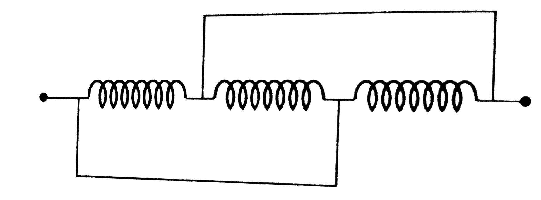
View SolutionPure inductance of `3.0 H` is connected as shown below. The equivalent inductance of the circuit is
View SolutionThe equivalent inductance of two inductances is `2.4` henry when connected in parallel and `10` henry when connected in series. The difference between the two inductance is
View Solutionthe resistance and inductance of series circuit are `5Omega` and `20H` respectively. At the instant of closing the switch, the current is increasing at the rate `4A-s`. The supply voltage is
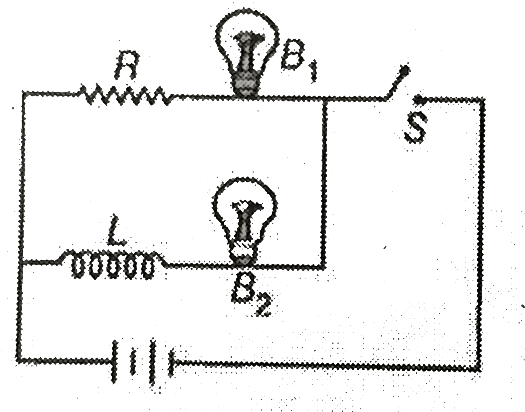
View SolutionFigure represents two bulbs `B_(1)" and " B_(2)`resister R and inductor L. When the switch S in turned off, then
View SolutionAn inductance `L` and a resistance `R` are first connected to a battery. After some time the battery is disconnected but `L` and `R` remain connected in a closed circuit. Then the current reduces to `37%` of its initial value in
View SolutionIn an `LR`-circuit, time constant is that time in which current grows from zero to the value (where `I_(0)` is the steady state current)
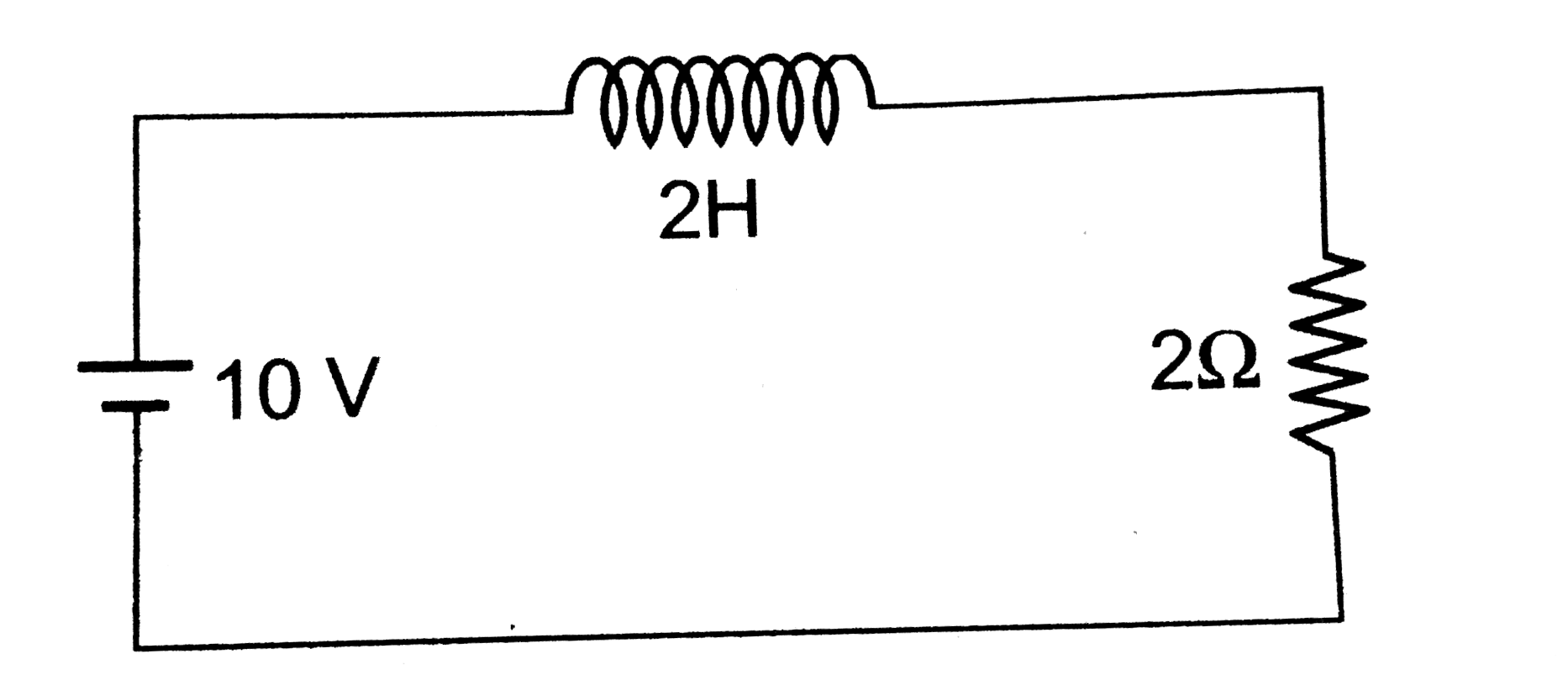
View SolutionIn the figure magnetic energy stored in the coil is
View SolutionA `LC` circuit is in the state of resonance. If `C=0.1muF` and `L=0.25` henry. Neglecting ohmic resistance of circuit what is the frequency of oscillations?
View SolutionAn oscillator circuit consists of an inductance of `0.5mH` and a capacitor of `20muF`. The resonant frequency of the circuit is nearly
View SolutionA coil of inductance 300mH and resistance `2 Omega. The current reaches half of its steady state value in
View SolutionIn series with `20 ohm` resitor a `5` henry inductor is placed. To the combination an e.m.f. of `5` volt is applied. What will be the rate of increase of current at `t=0.25 sec`?
View SolutionA`50` volt potential difference is suddenly applied to a coil with `L=5xx10^(-3)` henry and `R=180 ohm`. The rate of increase of current after `0.001` second is
View SolutionThe current in a `LR` circuit builds up to `(3)/(4th)` of its steady state value ion `4s`. The time constant of this circuit is
View SolutionIn the circuit shown in figure switch `S` is closed at time `t=0`. The charge which passes through the battery in one time constant is
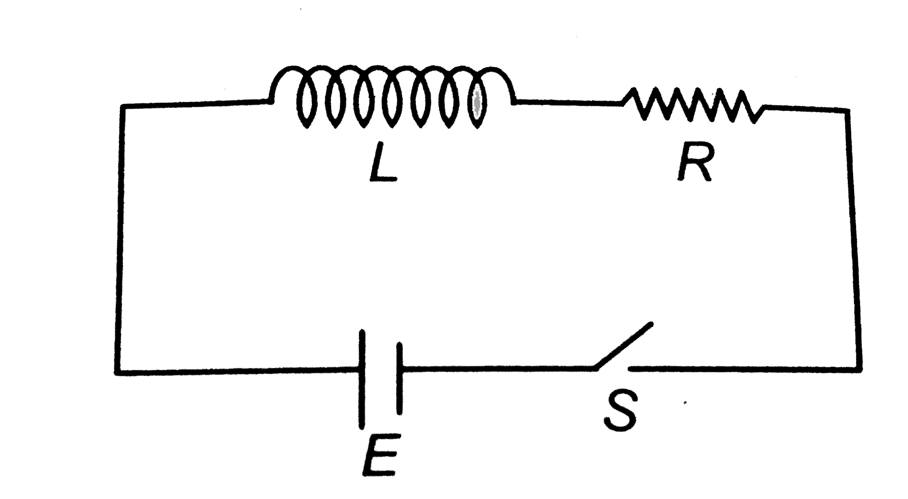
View SolutionThe resistance in the following circuit is increase at a particle instant. At this instant the value of resistanc eis `10Omega`. The current in the circuit will be now
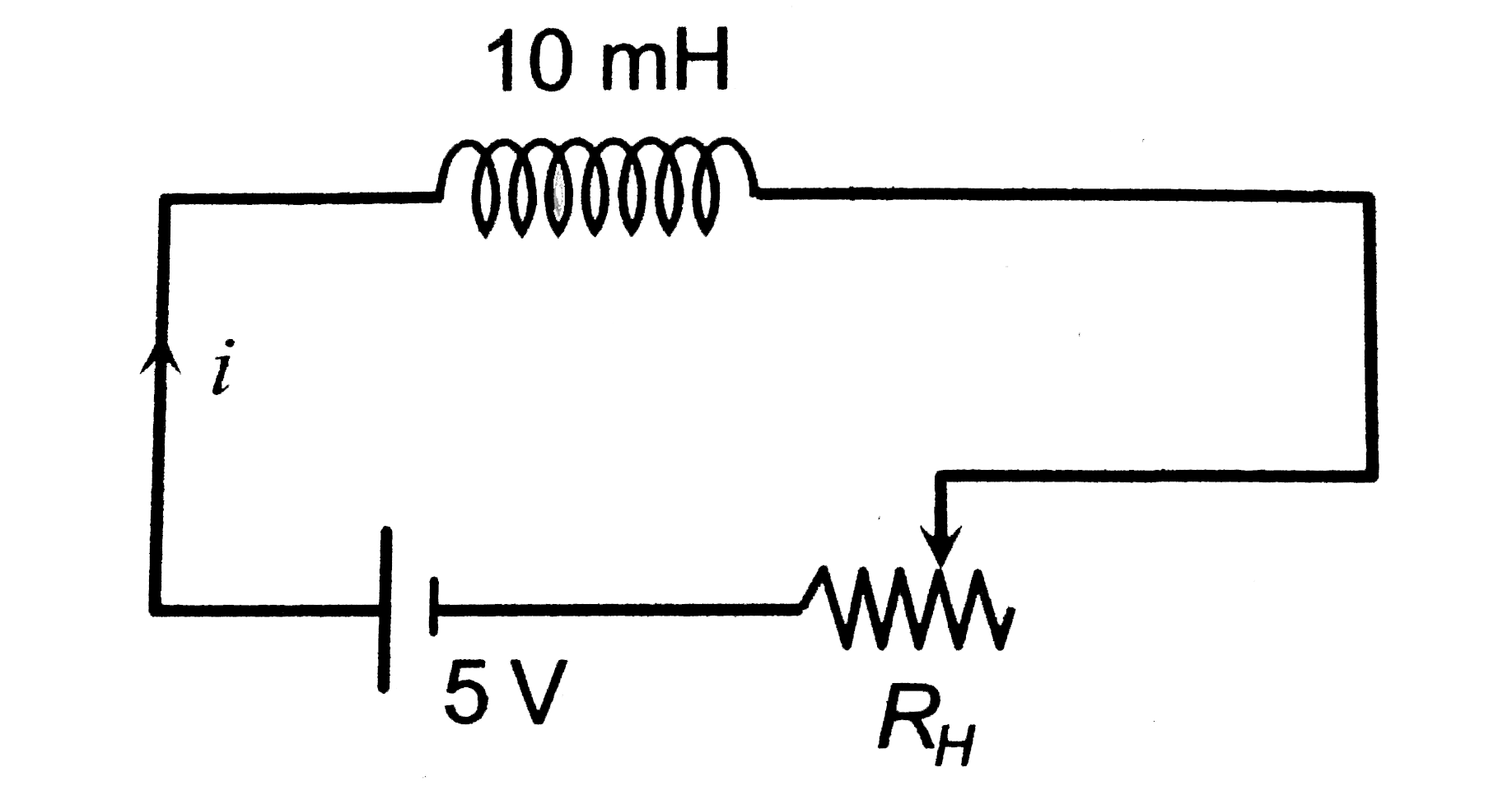
View SolutionIn the current shown Fig., `X` is joined to `Y` for a long time and then `X` is joined to `Z`. The total heat produced in `R_(2)` is
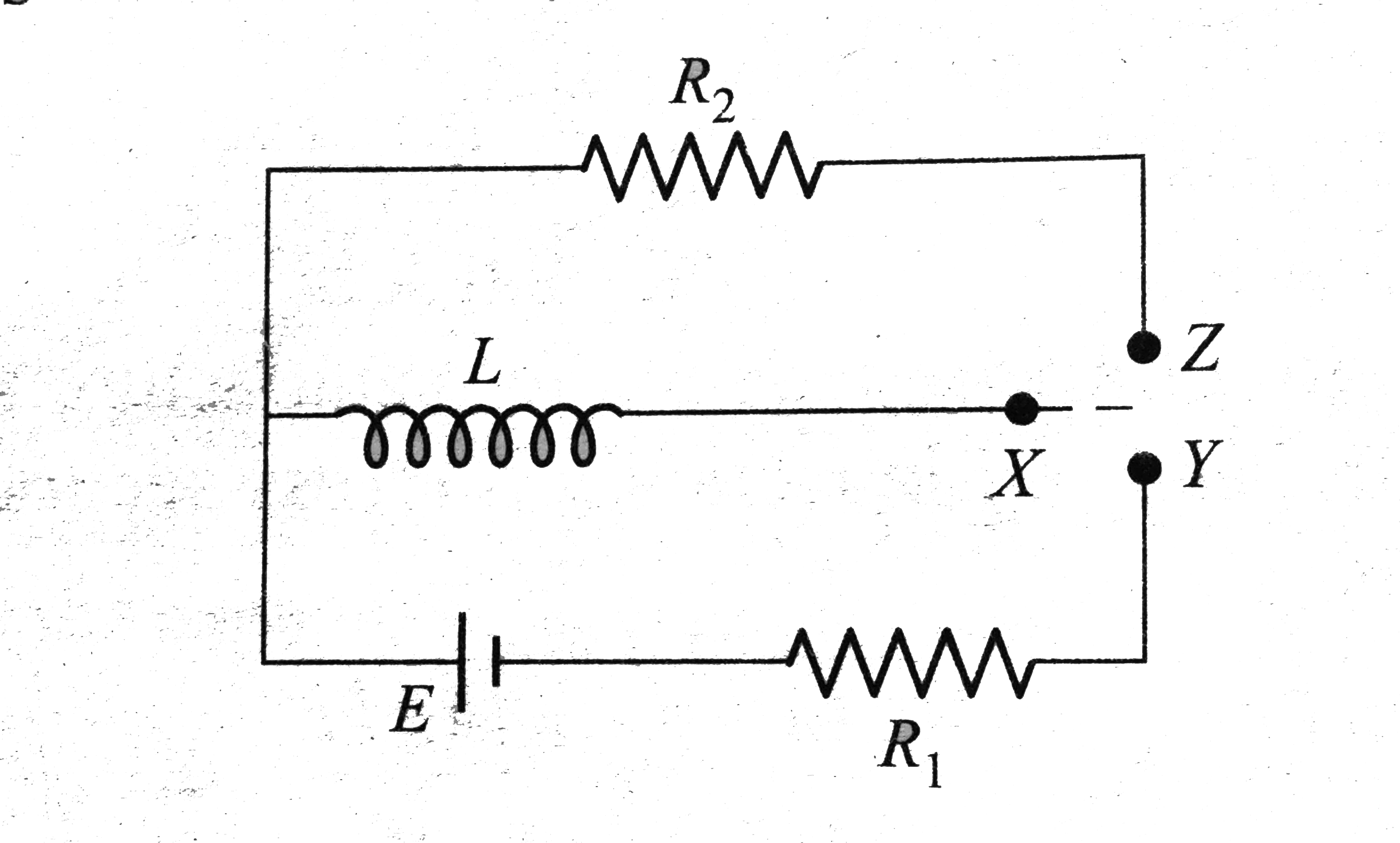
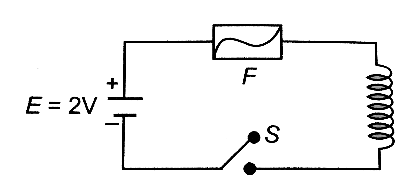
View SolutionIn the circuit shown, the cell is deal. The coil has an inductance of `4H` and zero resistance. `F` is a fuse of zero resistance and will blow when the current through it reaches `5 A`. The switch is closed at `t=0`. The fuse will blow:
View SolutionThe figure shows three circuit with identical batteries, inductors, and resistors. Rank the circuit according to the current through the battery (i) just after the switch is closed and (ii) a long time later, greatest first
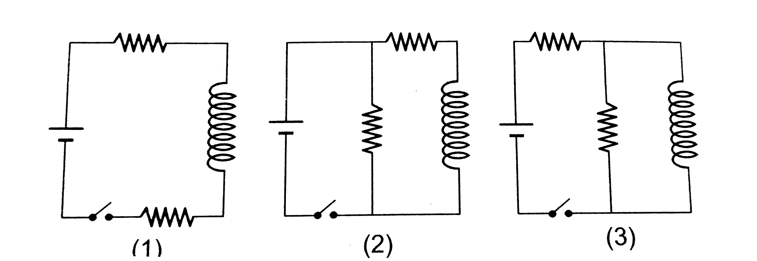
View SolutionIn which of the following circuits is the current maximum just after the switch `S` is closed?

View SolutionAn e.m.f. of `15` volt is applied in a circuit containing `5` henry inductance and `10` ohm resistance. The ratio of the current at time `t=oo` and at `t=1` second is
View SolutionSwitch `S` of the circuit shows in Fig. is closed at `t = 0`. If `e` denotes the induced emf in `L` and `i` the current flowing through the circuit at time `t`, then which of the following graphs correctly represents the variation of `e` with `i`?
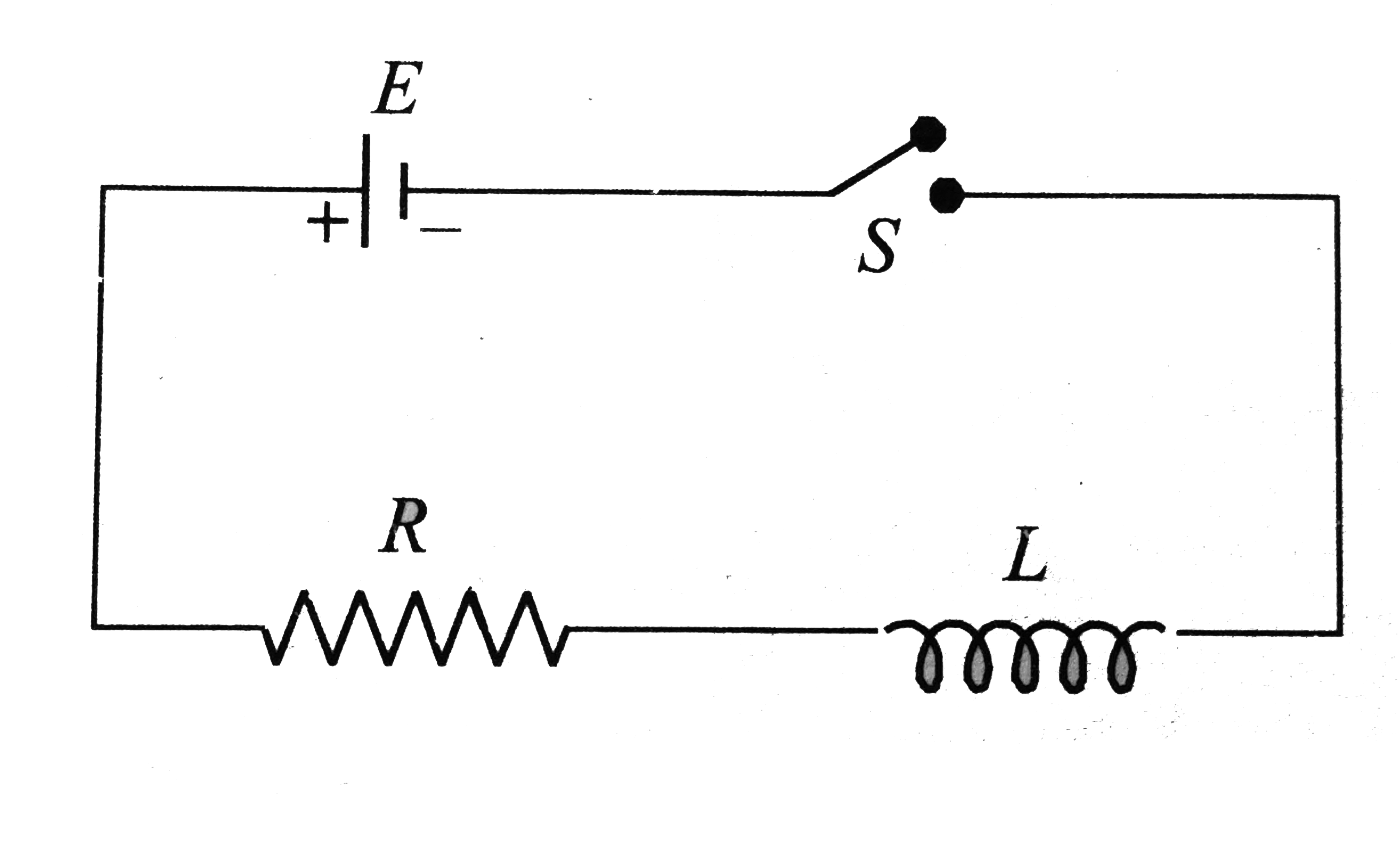
View SolutionIn the given circuit, let `i_(1)` be the current drawn battery at time `t=0` and `i_(2)` be steady current at `t=oo` then the ratio `(i_(1))/(i_(2))` is
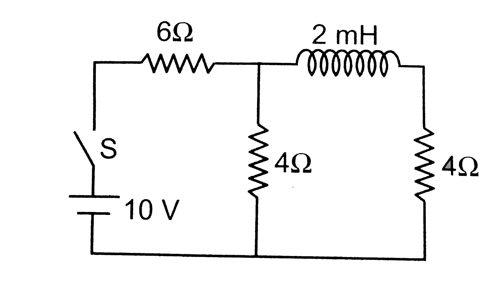
View SolutionIn the circuit shown in Fig. Sliding contact is moving with uniform velocity towards right. Its value at some instance is `12 (Omega)`. The current in the circuit at this instant of time will be

View SolutionConsider the circuit shown in figure. The current through the battery a long time after the switch `S` is closed is:

View Solutionin the previous question, suppose the switch is again opened at `t=0, then time constant of discharging circuit is:
View SolutionIn the circuit shown in figure switch `S` is closed at time `t=0`. The charge which passes through the battery in one time constant is

View Solution
Inductor Circuits questions and complete solutions for chapter ELECTROMAGNETIC INDUCTION of A2Z PHYSICS (HINGLISH) of Class 12