Complete Solutions to Problems Based On Mixed Concepts of chapter ALTERNATING CURRENT of Class 12 book with complete answers and questions
| Class 12 | PHYSICS |
| Chapter | ALTERNATING CURRENT |
| A2Z | Problems Based On Mixed Concepts |
| Number Of Questions | 40 |
| Academic Year | 2023-24 |
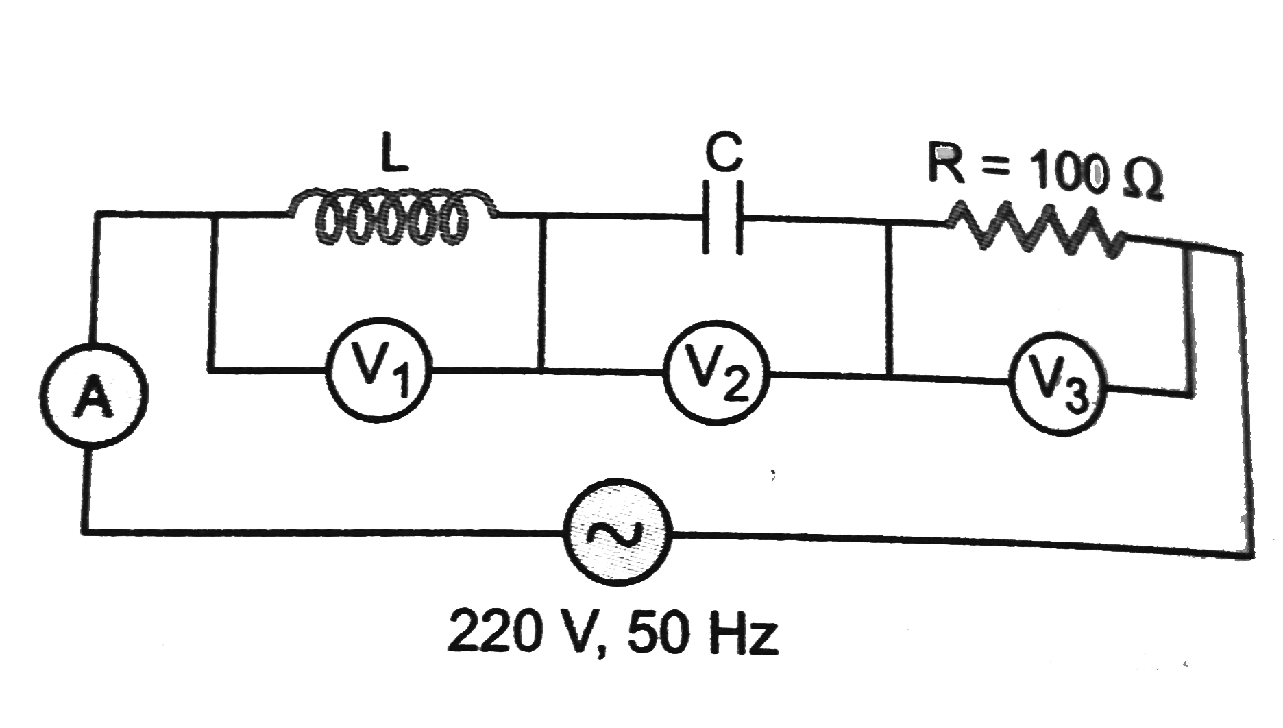
In the given circuit, Fig., the reading of voltmeter `V_(1)` and `V_(2)` 300 votls each. The reading of the voltemeter `V_(3)` and ammeter `A` are respectively
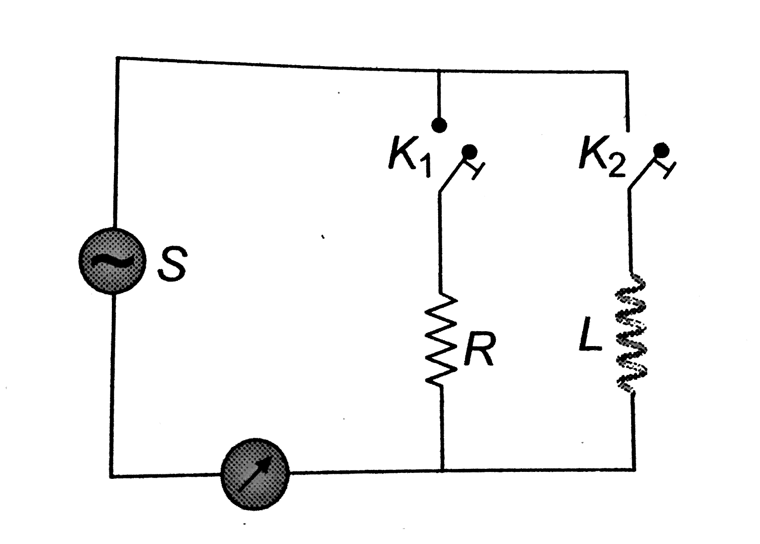
View SolutionIn the circuit shown here, `R` is pure resistor, `L` is an inductor of negligible resistance (as compared to `R`), `S` is a `100 V, 50Hz AC` source of negligible resistance. With either key `K_(1)` alone or `K_(2)` alone closed, the current is `I_(0)`. if the source is changed to `100 V, 150 Hz` the current with `K_(1)`, alone closed and with `K_(2)` alone closed will be respectively.
View SolutionA transmitter transmits at a wavelength of `30` meter. A condenser or capacitance `2.4 muF` is being used. The value of the inductance for the resonant circuit is approximately.
View SolutionA resistor and an inductor are conneted in sires to a `220 "volt" AC` supply. When measured with an `AC` is `123` volts. Then the potential difference across the terminals of the inductor is
View SolutionIn a step-up transformer the turn ratio is `1:10`. A resistance of `200` ohm connected across the secondary is drawing a current of `0.5A`. What is the primary voltage and current?
View SolutionA 50 Hz a.c. current of crest value 1A flows through the primary of a transformer. If the mutual inductance between the primary and secondary be `1.5 H` , the crest voltage induced in secondary is-
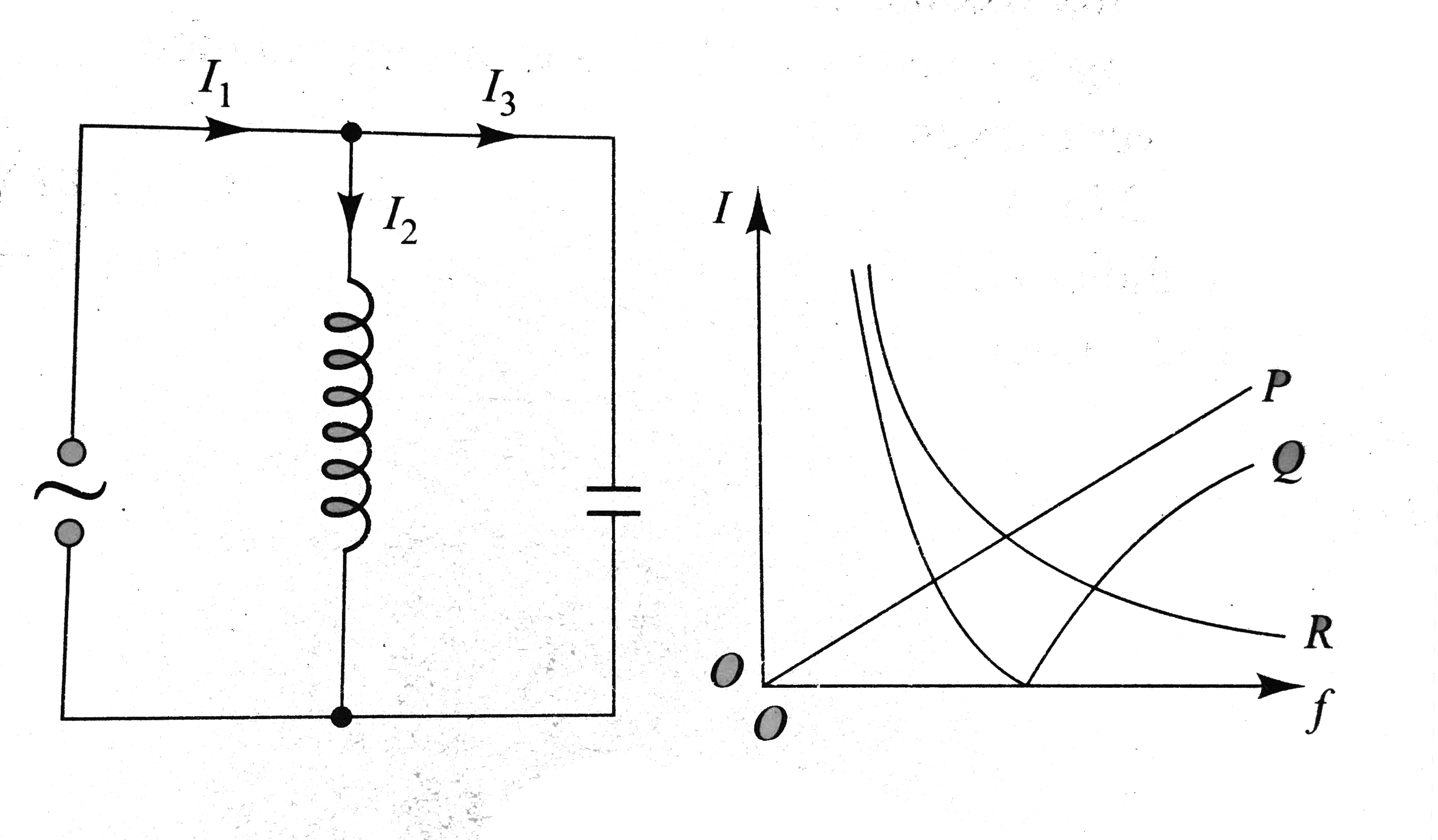
View SolutionIn the circuit shown if fig, the rms currents `(I_1), (I_2)` and` (I_3)` are altered by varying the frequency f of the oscillator. The output voltage of the oscillator remains sinusoidal and has a fixed amplitude.
When curves in figure correctly indicate the variation with frequency of the currents `(I_1), (I_2),and (I_3)`.
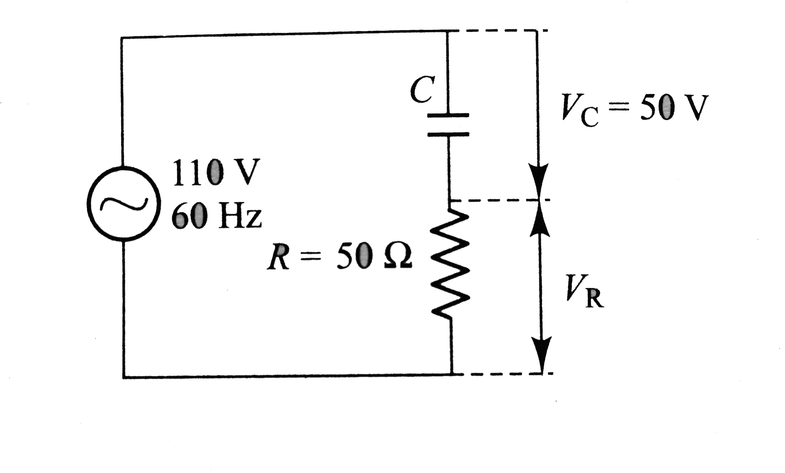
View SolutionIn the circuit given in fig. `(V_C)=50 V and R=50 Omega`. The values of C and `(V_R)` are
View SolutionA power transformer is used to set up an alternating e.m.f of `220V` to `4.4 kV` to transmits `6.6 kW` of power. The primary coil has `1000` turns. What is current rating of secondary? (Assume efficiency is `100%)`
View SolutionA 220-V, 50 Hz, ac generator is connected to an inductor and a `50 Omega` resistance in series. The current in the circuit is `1.0 A`. What is the PD across inductor?
View SolutionAn `8 muF` capacitor is connected across a 220 V, 50 Hz line. What is the peak value of charge through the capacitor?
View SolutionA coil of inductance `0.1 H` is connected to `50 V, 100Hz` generator and current is found to be `0.5A`. The potential difference across resistance of coil is:
View SolutionA dc ammeter and a hot wire ammeter are connected to a circuit in series. When a direct current is passed through circuit, the dc ammeter shows 6 A. When ac current flows through circuit, the ac ammeter shows 8A. What will be reading of each ammeter if dc and ac current flow simulataneously through the circuit?
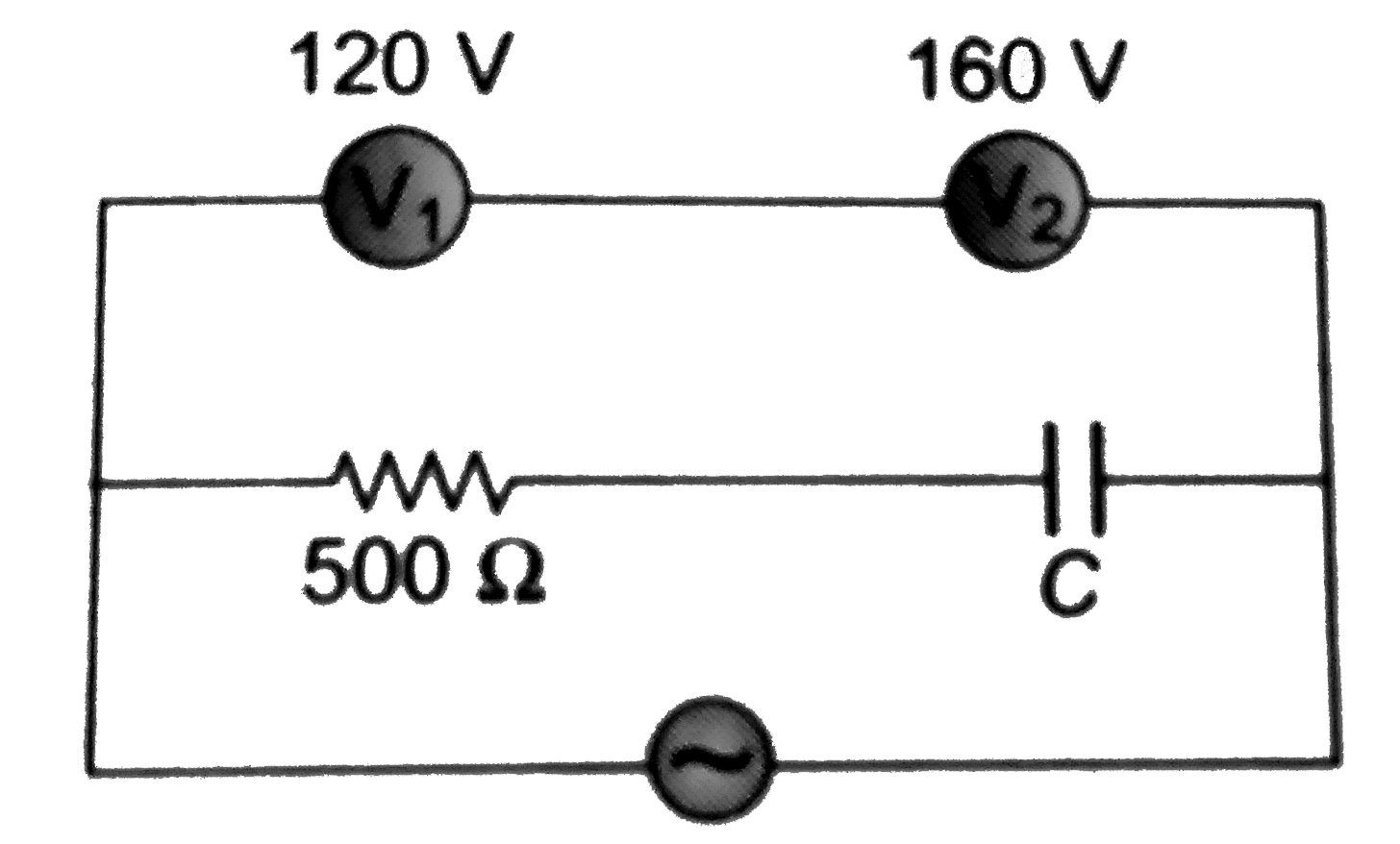
View SolutionA `500 Omega` resistor and a capacitor `C` are connected in series across `50 Hz AC` supply mains. The r.m.s potential difference recorded on voltmeter `V_(1)` and `V_(2)` are `V_(1)=120 V` and `V_(2)=160 V`. The power taken for the mains is:
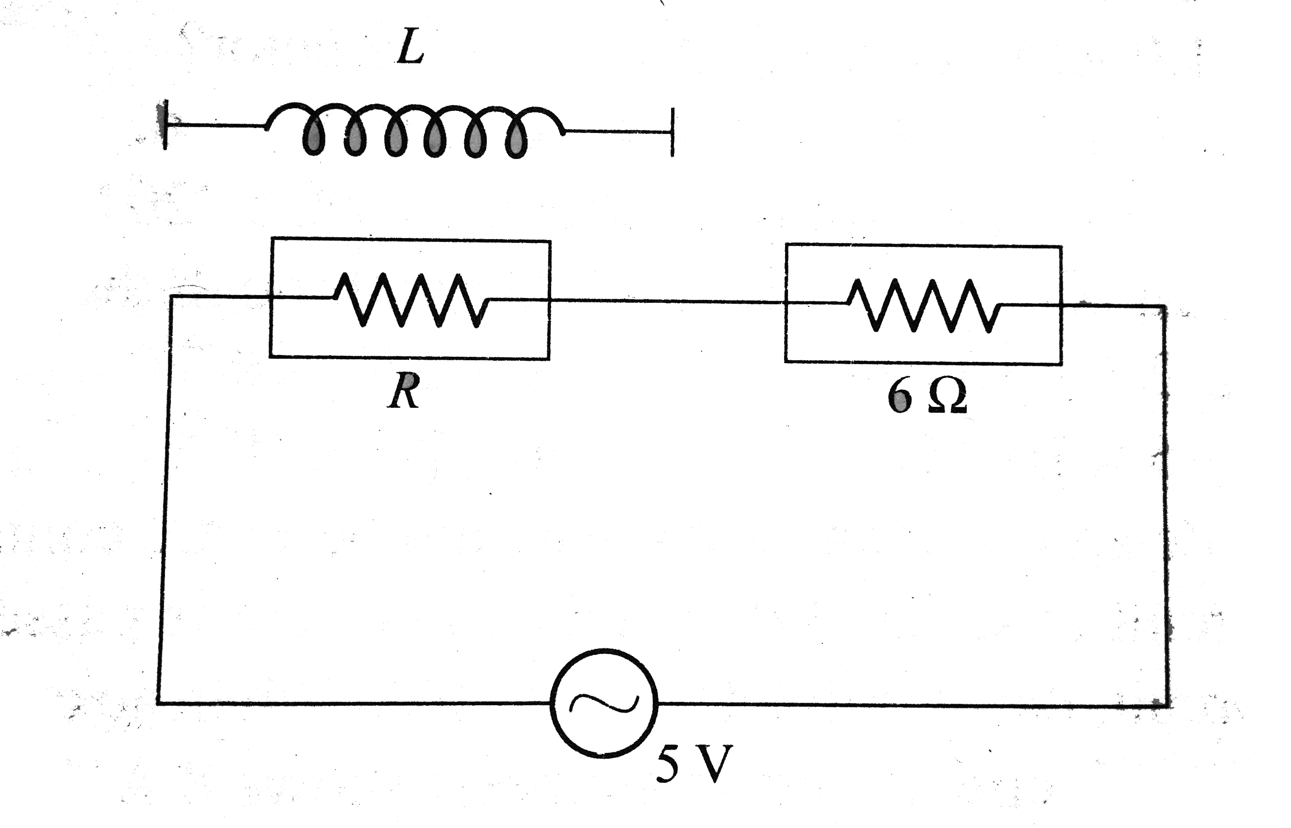
View SolutionTwo resistor are connected in series across a `5 V` rms source of alternating potential. The potential difference across `6 Omega` resistor is `3V`. If `R` is replaced by a pure inductor `L` of such magnitude that current remains same. Then the potential difference across `L` is
View SolutionA coil has an inductance of 0.7 H and is joined in series with a resistance of 220 ohm. Find the wattless component of current in the circuit, when an alternating e.m.f. of 220 V at a frequency of 50 Hz is supplied to it.
View SolutionIn the circuit shown in figure when the frequency of oscillator is increased, the reading of ammeter `A_(4)` is same as that of ammeter.
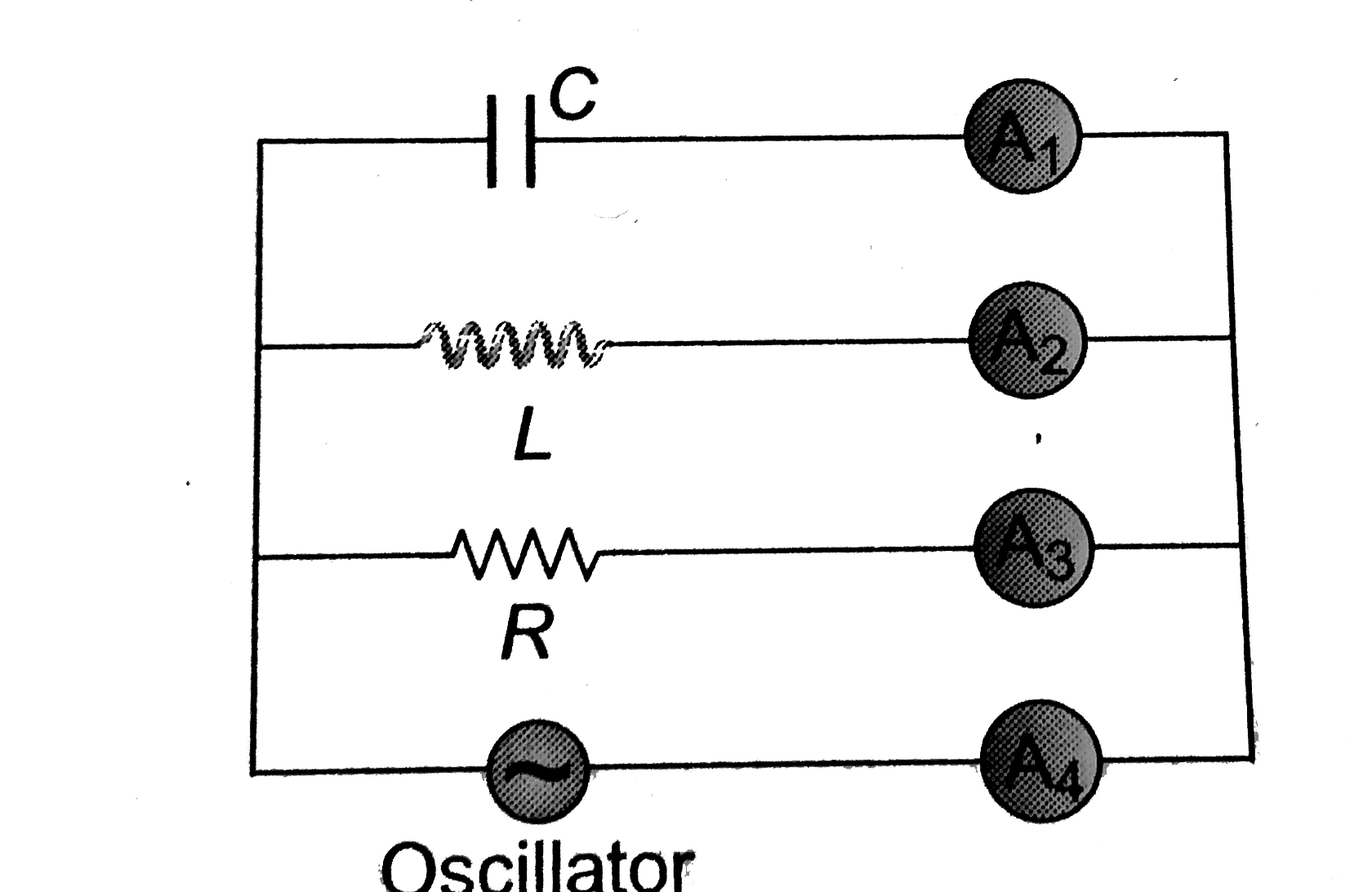
View SolutionIn the figure shown, three `AC` voltmeters have been connected. At resonance, the reading of
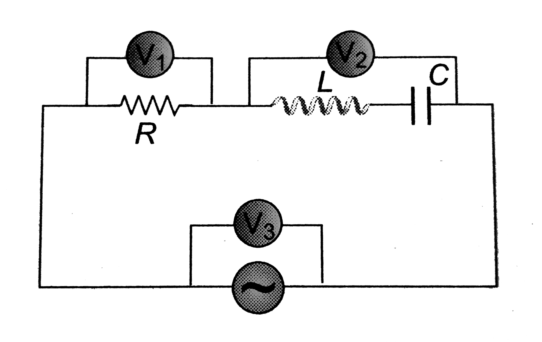
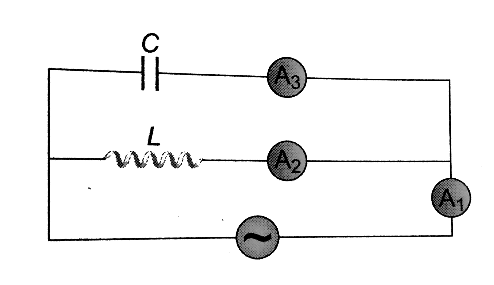
View SolutionAn inductor `L`, a capacitor `C` and `AC` ammeters `A_(1),A_(2)` and `A_(3)` are connected in the circuit as shown. When the frequency of the oscillators is increased, then at resonant frequency, the reading of ammeter ?
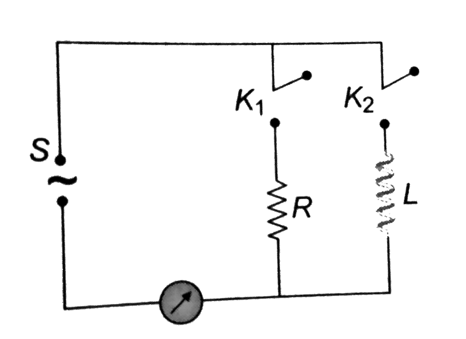
View SolutionIn the circuit shown, `R` is a pure resistor, `L` is an inductor of negligible resistance (as compared to `R`) and `S` is a`100V,50 Hz AC` source of negligible resistance. With eigther key `k_(1)` alone or `k_(2)` alone closed, the current is `I_(0)`. if the source is changed to `100 V, 100 Hz`, the current with `k_(1)` alone closed and with `k_(2)` alone closed will be respectively
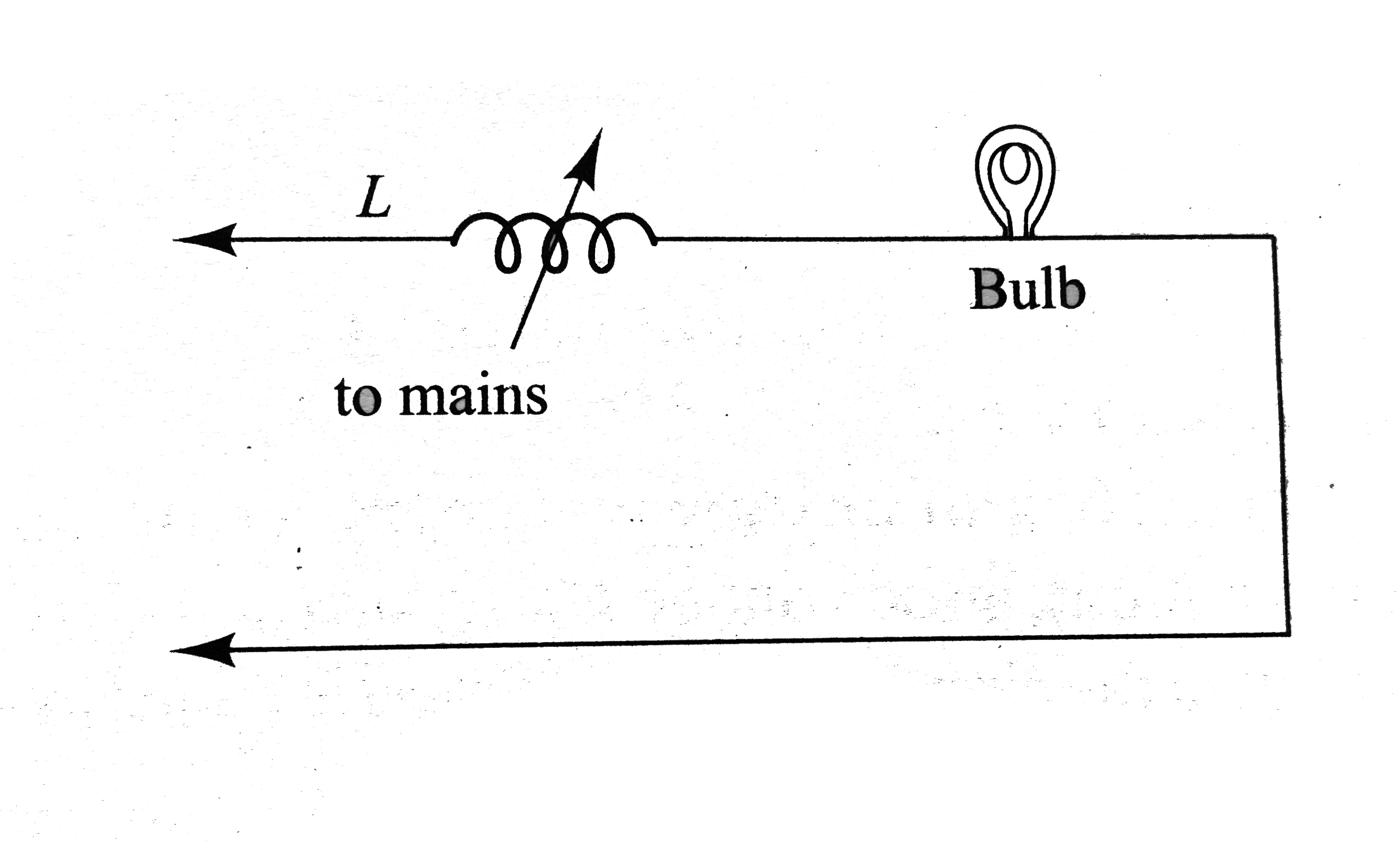
View SolutionA typical light dimmer used to dim the stage lights in a theater consists of a variable induction for L (where inductance is adjustable between zero and `L_(max)`) connected in series with a light bulb B as shown in fig. the mains electrical supply is 220 V at 50 Hz, the light bulb is rated at 220 V, 1100 W. What `(L_(max))` is required if the rate of energy dissipated in the light bulb is to be varied by a factor of 5 from its upper limits of 1100 W?
View SolutionIf the instantaneous current in a circuit is given by `i=2cos (omegat-phi)`ampere, the r.m.s. value of the current is
View SolutionA coil has an inductance of 0.7 H and is joined in series with a resistance of 220 ohm. Find the wattless component of current in the circuit, when an alternating e.m.f. of 220 V at a frequency of 50 Hz is supplied to it.
View SolutionIn a region of uniform magnetic inductance `B=10^(-2)`tesla. A circular coil of radius `30 cm` and resistance `pi^(2) ohm` is rotated about an axis which is perpendicular to the direction of `B` and which forms a diameter of the coil. If the coil rotates at `200` r.p.m the amplitude of the alternating current induced in the coil is
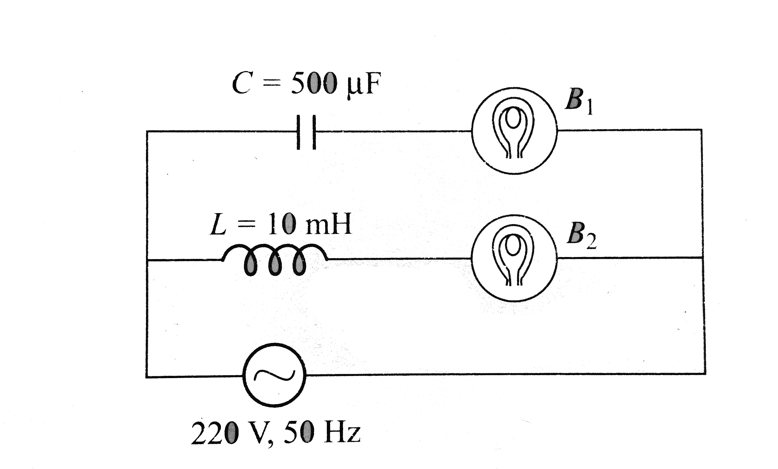
View SolutionIn the circuit shown in fig. if both the bulbs `(B_1) and (B_2)` are identical
View SolutionIn a region of uniform magnetic inductance `B=10^(-2)`tesla. A circular coil of radius `30 cm` and resistance `pi^(2) ohm` is rotated about an axis which is perpendicular to the direction of `B` and which forms a dimater of the coil. If the coil rotates at `200` r.p.m the amplitude of the alternatic current induced in the coil is
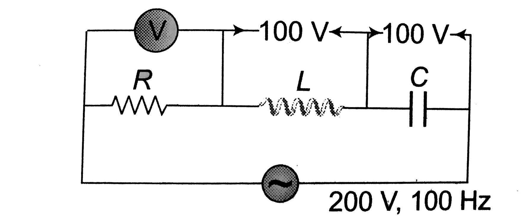
View SolutionIn the circuit given below, what will be the reading of the voltmeter?
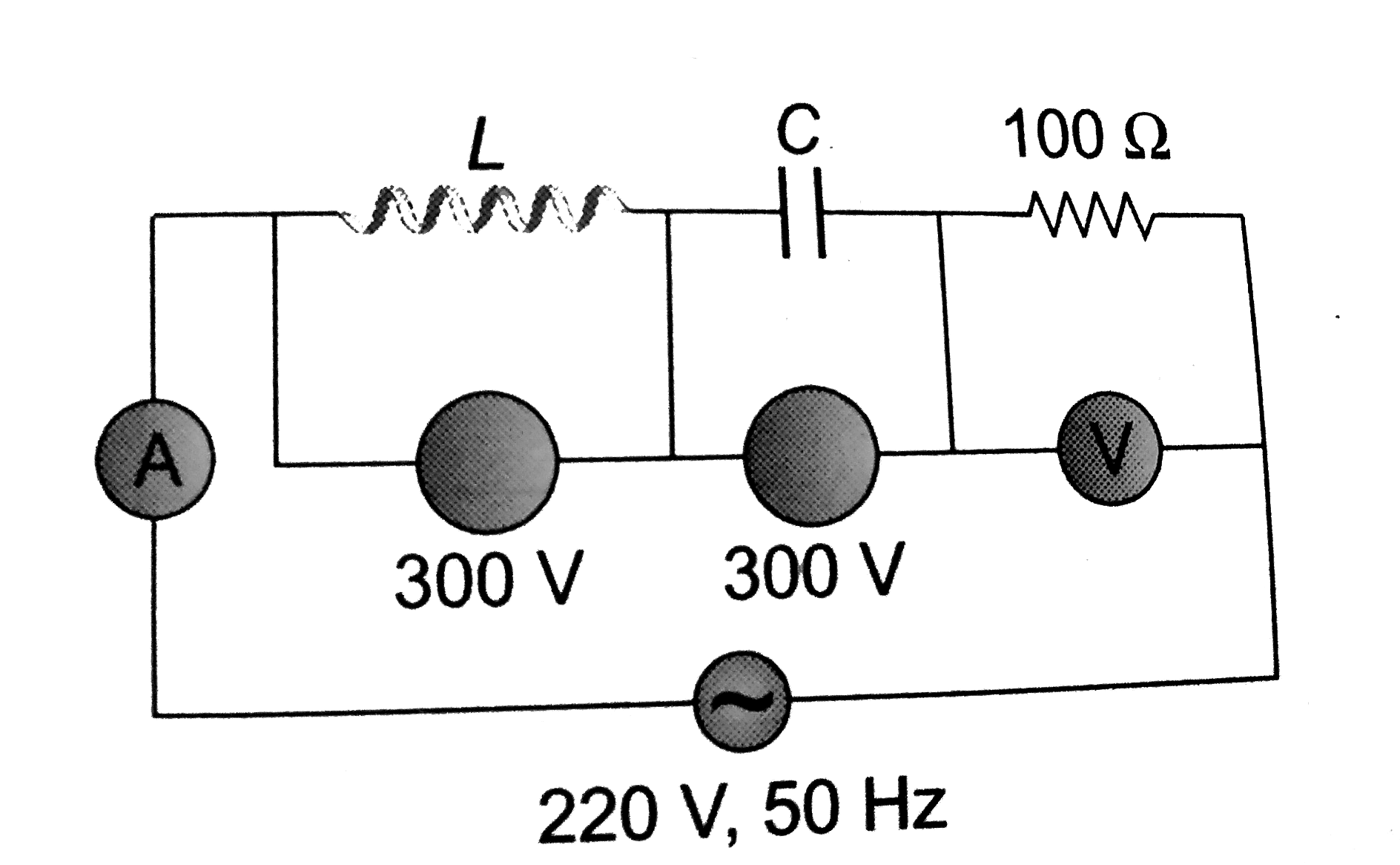
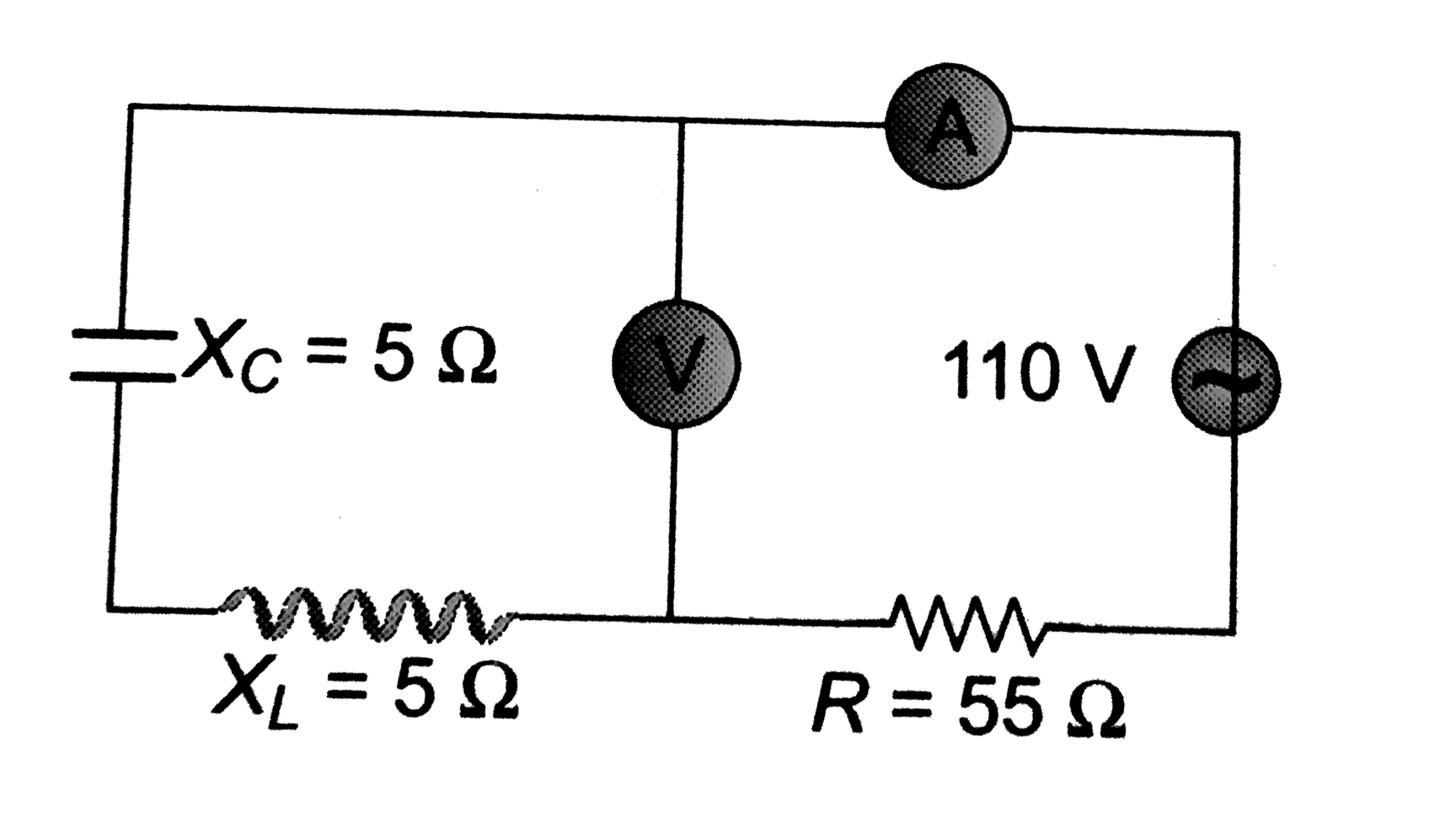
View SolutionIn the circuit shown below, what will be the reading of the voltmeter and ammeter?
View SolutionThe diagram shows a capacitor `C` and a resistor `R` connected in series to an `AC` source. `V_(1)` and `V_(2)` are voltmeters and `A` is ammeter
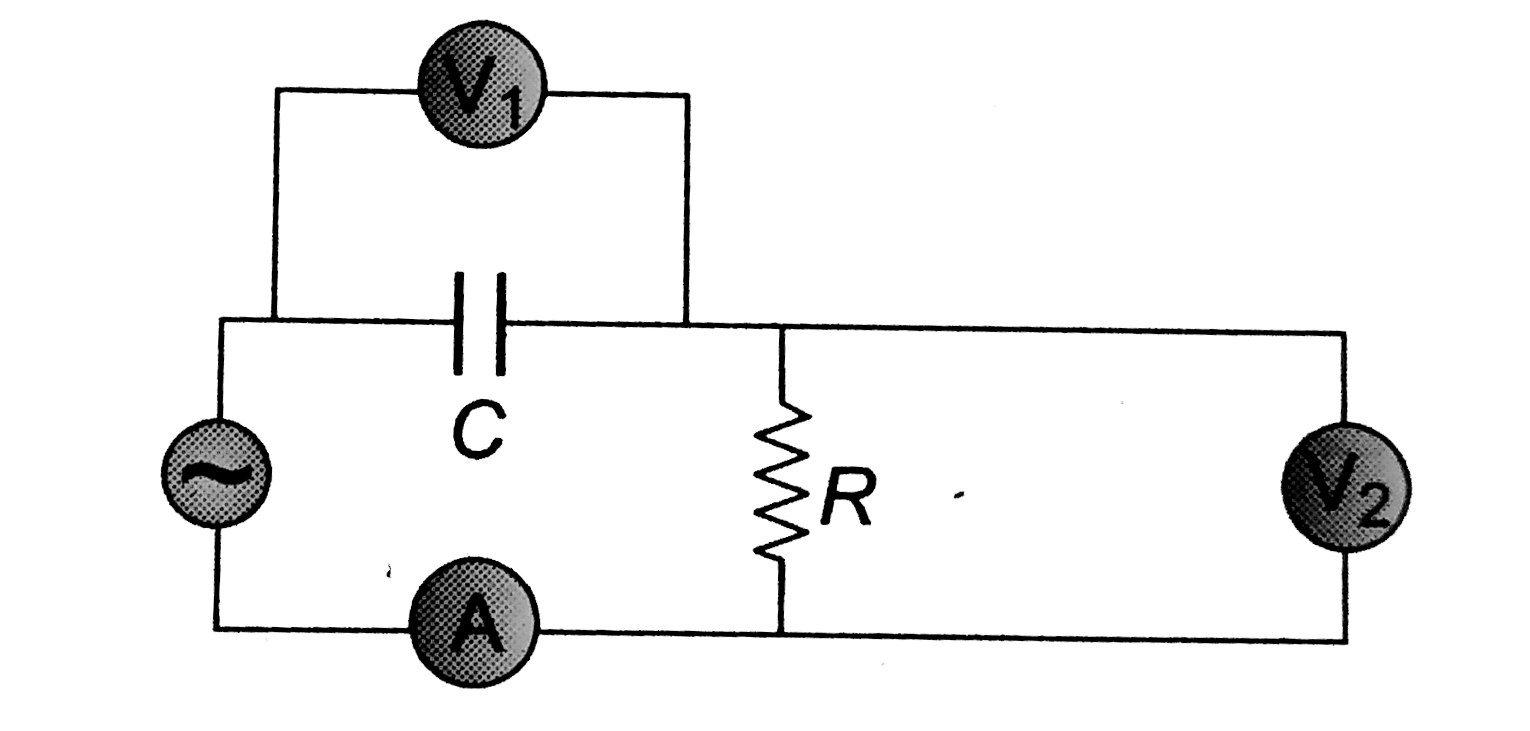
Now, consider the following statements :
(I) Reading in `A` and `V_(2)` are always in phase.
(II) Reading in `V_(1)` is ahead in phase with reading in `V_(2)`,
(III) Reading in `A` and `V_(1)` are always in phase. Which of these statements are/is correct
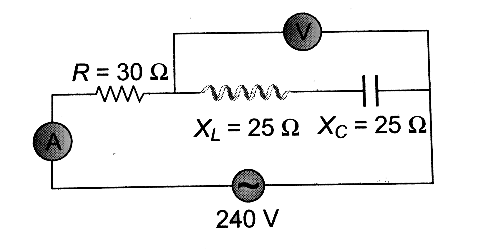
View SolutionIn the circuit shown in figure neglecting source resistance the voltmeter and ammeter reading will respectively, will be
View SolutionIn the circuit shown in figureure the `AC` source gives a voltage `V=20cos(2000t)`. Neglecting source resistance, the voltmeter and and ammeter readings will be
 .
.
View SolutionA telephone wire of length `200 km` has a capacitance of `0.01 4 (muF)/(km)`. If it carries an `AC` of frequency `5kHz` what should be the value of an inductor required to be connected in series so that impedence of the circuit is minimum ?
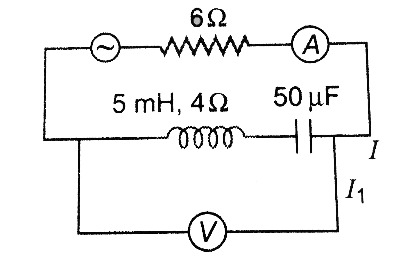
View SolutionThe reading of ammeter in the circuit shown will be
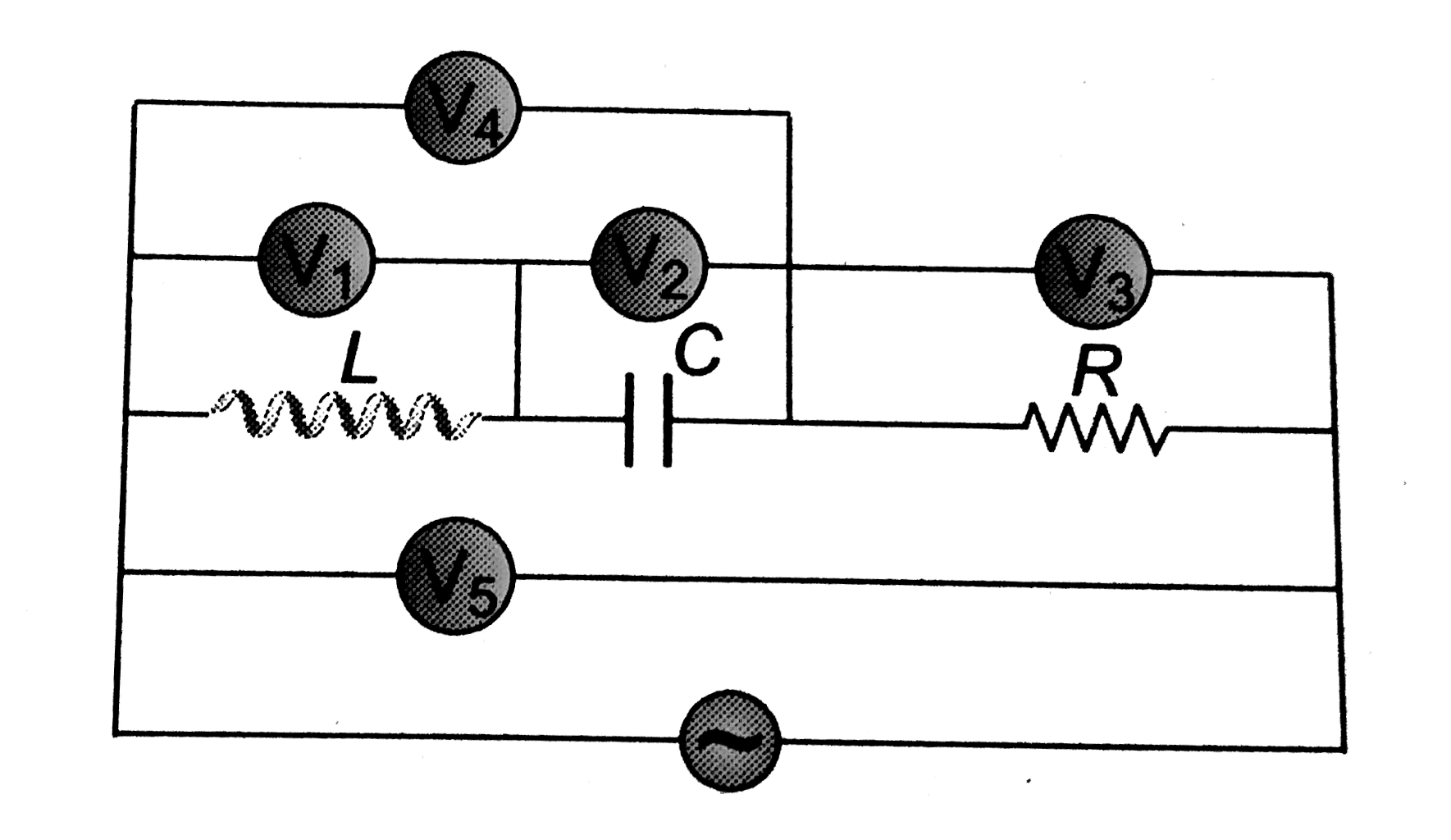
View SolutionIn the adjoining `AC` circuit the voltmeter whose reading will be zero at resonance is
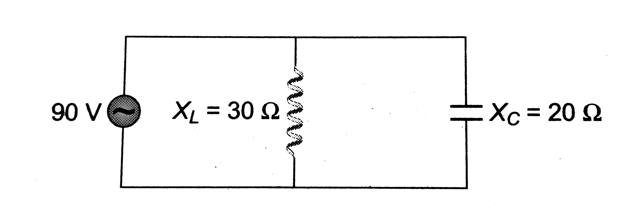
View SolutionIn the adjoining figure the impedence of the circuit will be
View SolutionIn a series circuit `C=2muF,L=1mH` and `R=10 Omega`, when the current in the circuit is maximum, at that time the ratio of the energies stored in the capacitor and the inductor will be
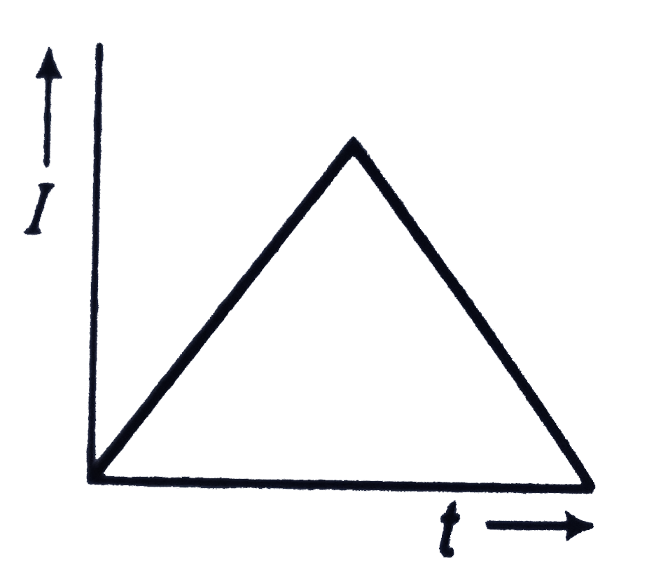
View SolutionAn alternating current `I` in an inductance coil varies with time `t` according to the graph as shown: Which one of the following graph gives the variation of voltage with time?
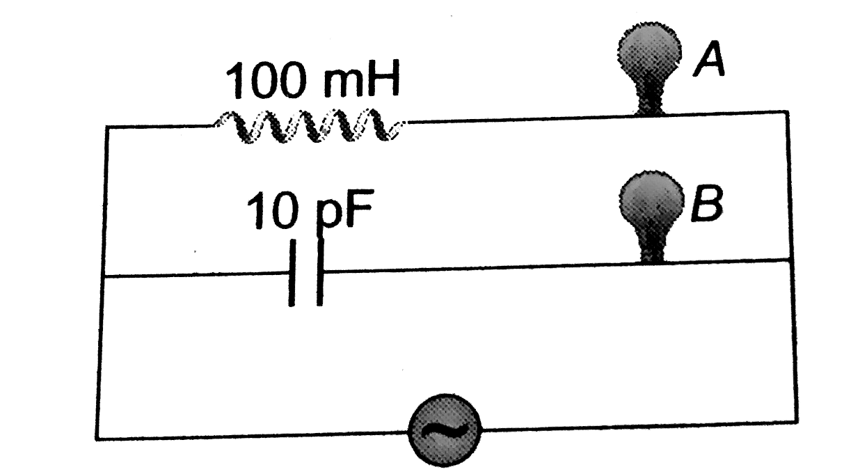
View SolutionIf `A` and `B` are identical bulbs, which bulb glows brighter?
View SolutionIn an `LCR` circuit `R=100 Omega`. When capacitance `C` is removed, the current lags behind the voltage by `pi//3`. When inductance `L` is removed, the current leads the voltage by `pi//3`. The impedance of the circuit is
View SolutionFollowing figure shows an `AC` generator connected to a "block box" through a pair of terminals. The box contains possible `R,L,C` or their combination, whose elements and arrangements are not known to us.
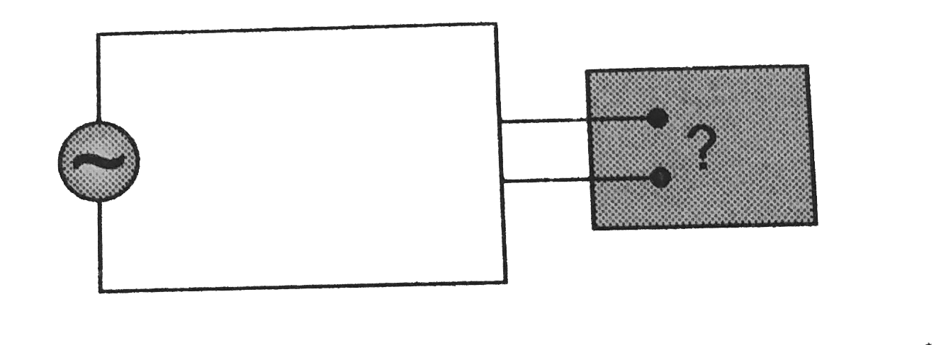
Measurements, outside the box reveals that `e=75 sin(omega t) `volts, `i=1.5 sin(omegat+45^(@))` ampere. Then the wrong statement is
View Solution
Problems Based On Mixed Concepts questions and complete solutions for chapter ALTERNATING CURRENT of A2Z PHYSICS (HINGLISH) of Class 12