Complete Solutions to Exercises Single Correct of chapter ALTERNATING CURRENT of Class 12 book with complete answers and questions
| Class 12 | PHYSICS |
| Chapter | ALTERNATING CURRENT |
| CENGAGE PHYSICS | Exercises Single Correct |
| Number Of Questions | 63 |
| Academic Year | 2023-24 |
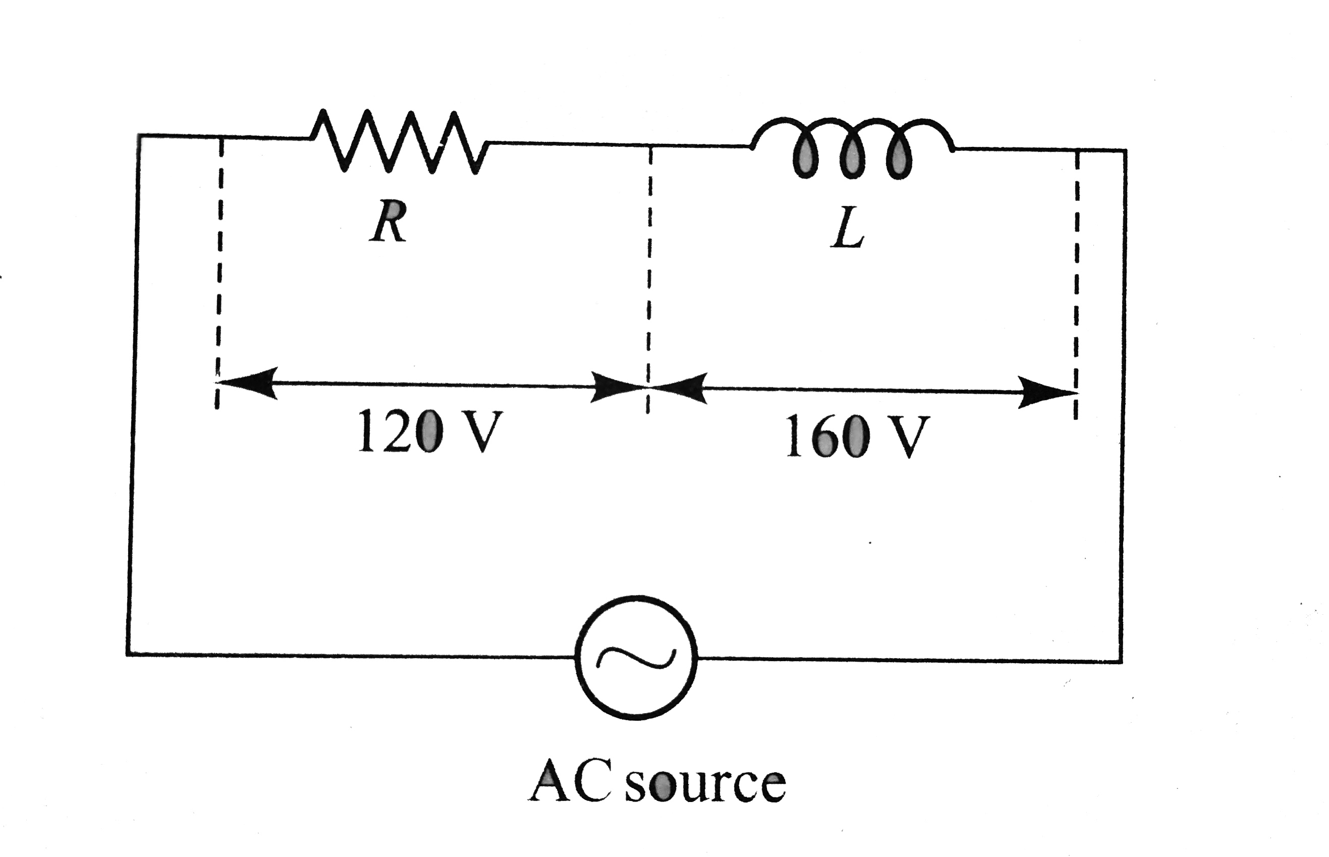
The circuit given in fig. has a resistanceless choke coil L and a resistance R. The voltage across R and L are also given in the figure. The virtual value of the applied voltage is
View SolutionTwo sinusoidal voltage of the same frequency are shown in the diagram. What is the frequency, and the phase relationship between the voltage?
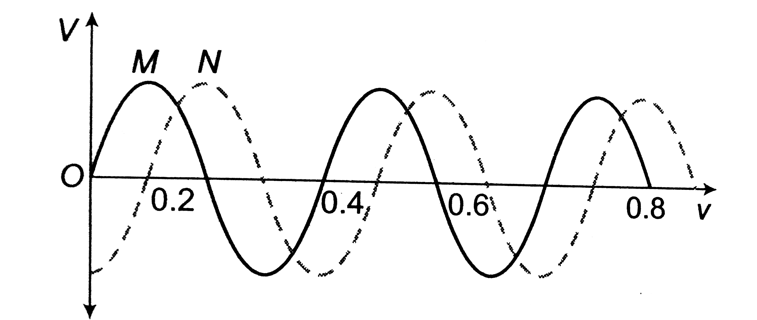
Frequency in `Hz` phase lead of `N` over `M` in radius
View SolutionFigure shows an iron-cored transformer assumed to be 100% efficient. The ratio of the secondaty turns to the primary turns is 1:20.
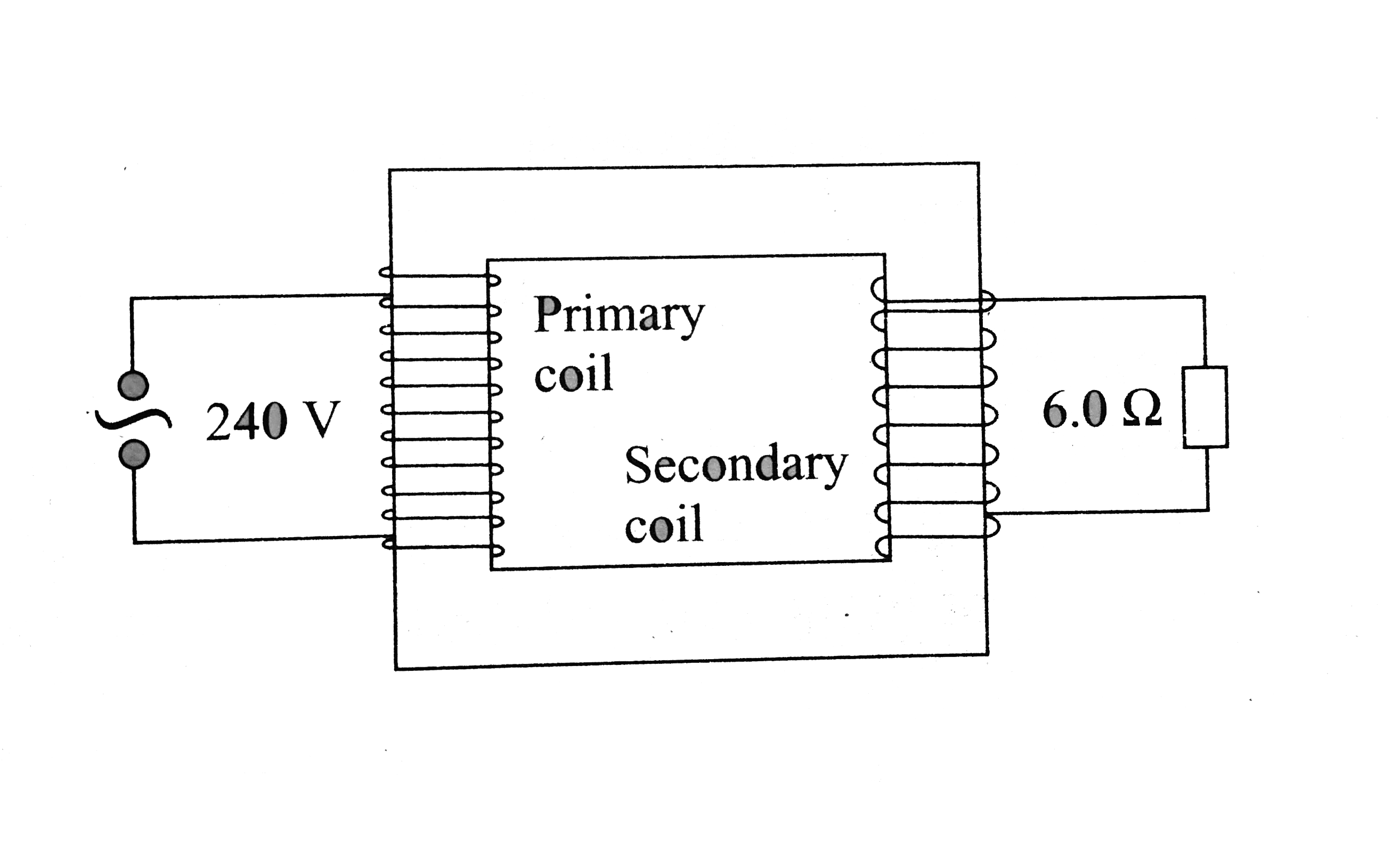
A 240 V ac supply is connected to the primary coil and a `6 Omega` resistor is connected to the secondary coil. What is the current in the primary coil?
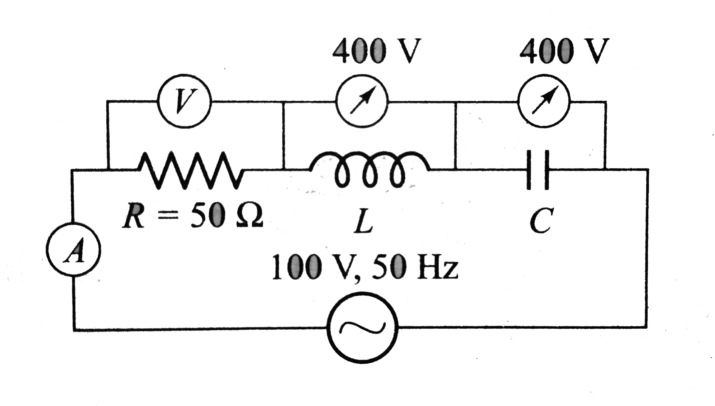
View SolutionIn the series LCR circuit , the voltmeater and ammeter reading are:
View SolutionAn LCR circuit contains resistance of `100 Omega` and a supply of 200V at 300 rad angular frequency. If only capacitance is taken out from the circuit and the rest of the circiut is joined, current lags behind the voltage by `60^(@)` . If, on the other hand , only inductor is taken out, the current flowing in the circuit is
View SolutionThe rms value of an ac of 50Hz is 10A. The time taken be an alternating current in reaching from zero to maximum value and the peak value will be
View SolutionThe peak value of an alternating emf E given by
`E=(E_0) cos omega t`
is 10V and freqency is 50 Hz. At time `t=(1//600)s` the instantaneous value of emf is
View SolutionA coil has a iductance of 0.7H and is joined in series with a resistance of `220 Omega`. When an alternating emf of 220V at 50 cps is applied to it, then the wattless component of the current in the circuit is `(take 0.7 = 2.2)`
View SolutionWhen 100 V dc is applied across a solinoid, a current of 1.0 A flows in it. When 100 V ac is applied across the same coil. The current drops to 0.5A. If the frequency of the ac source is 50 Hz, the impedance and inductance of the solenoid are
View SolutionAn inductive coil has resisatance of `100 Omega`. When an ac sinal of frequency 1000 Hz is fed to the coil. The applied voltage leads the current by `45^(@)`. What is the inductance of the coil?
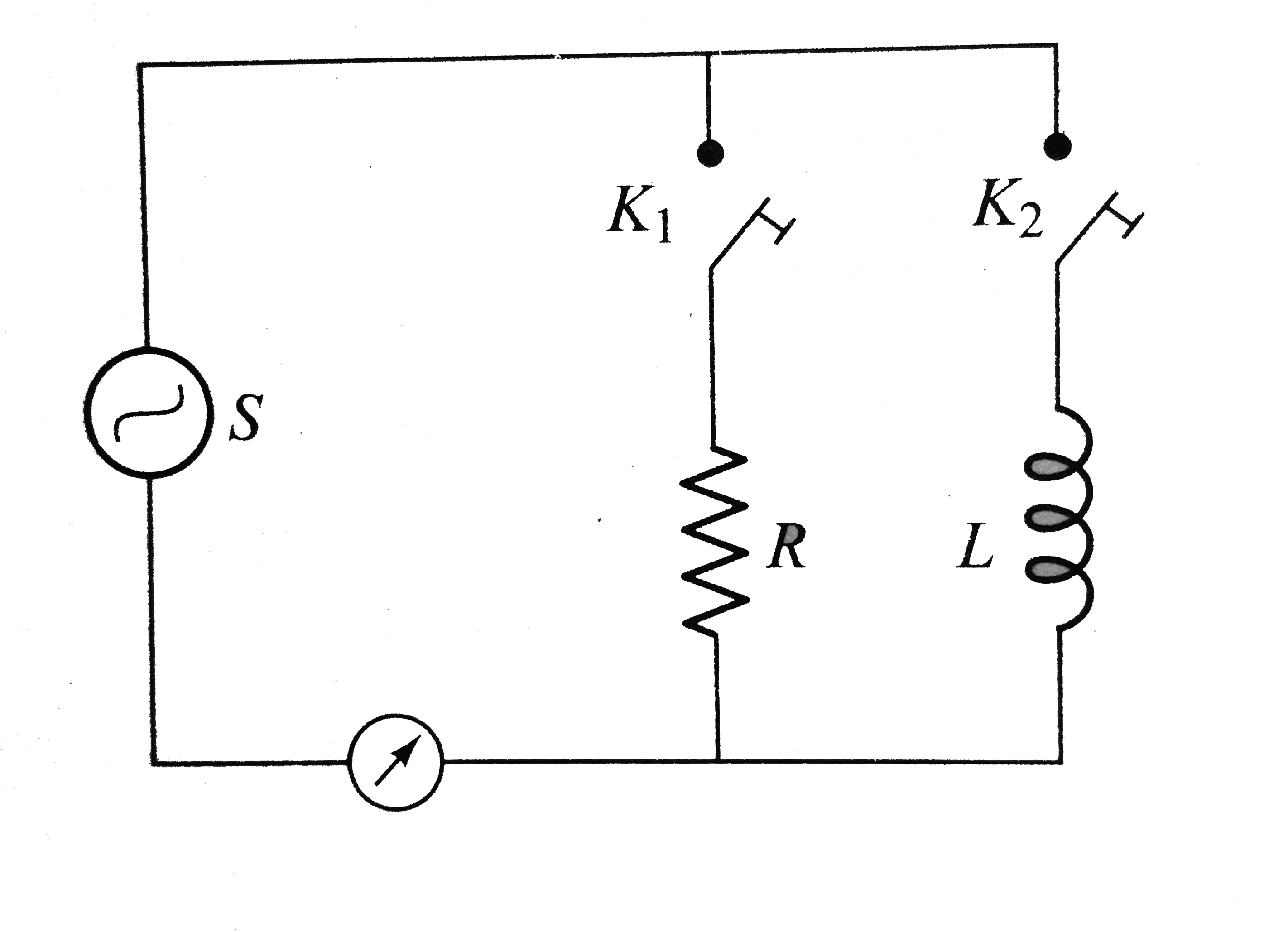
View SolutionIn the circuit shown in fig. R is a pure resistor, L is an inductor of ngligibe resistance (as compared to R), S is a 100 V , 50 Hz ac source of negligible resistnce. With either kiy `(K-1) `alone or `(K_2)` alone closed, the current is `(I_0)`. If the source os changed to 100 V, 100 Hz the current with `(K_1)` alone closed and with `(K_2)` alone closed will be, respectively.
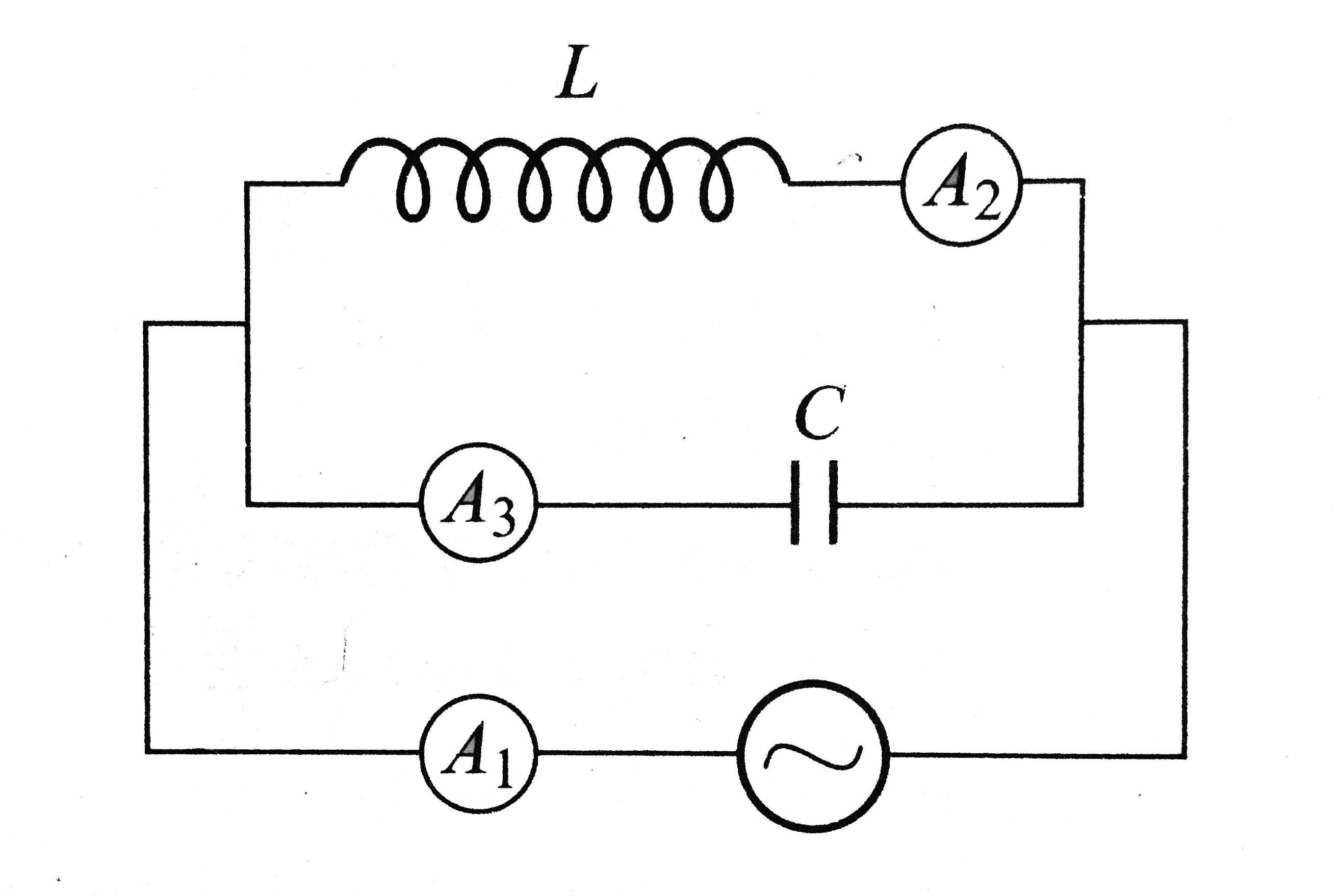
View SolutionFor the circuit shown in fig, the ammeter `A_(2)` reads 1.6A and ammeter `(A_3)` reads 0.4A. Then
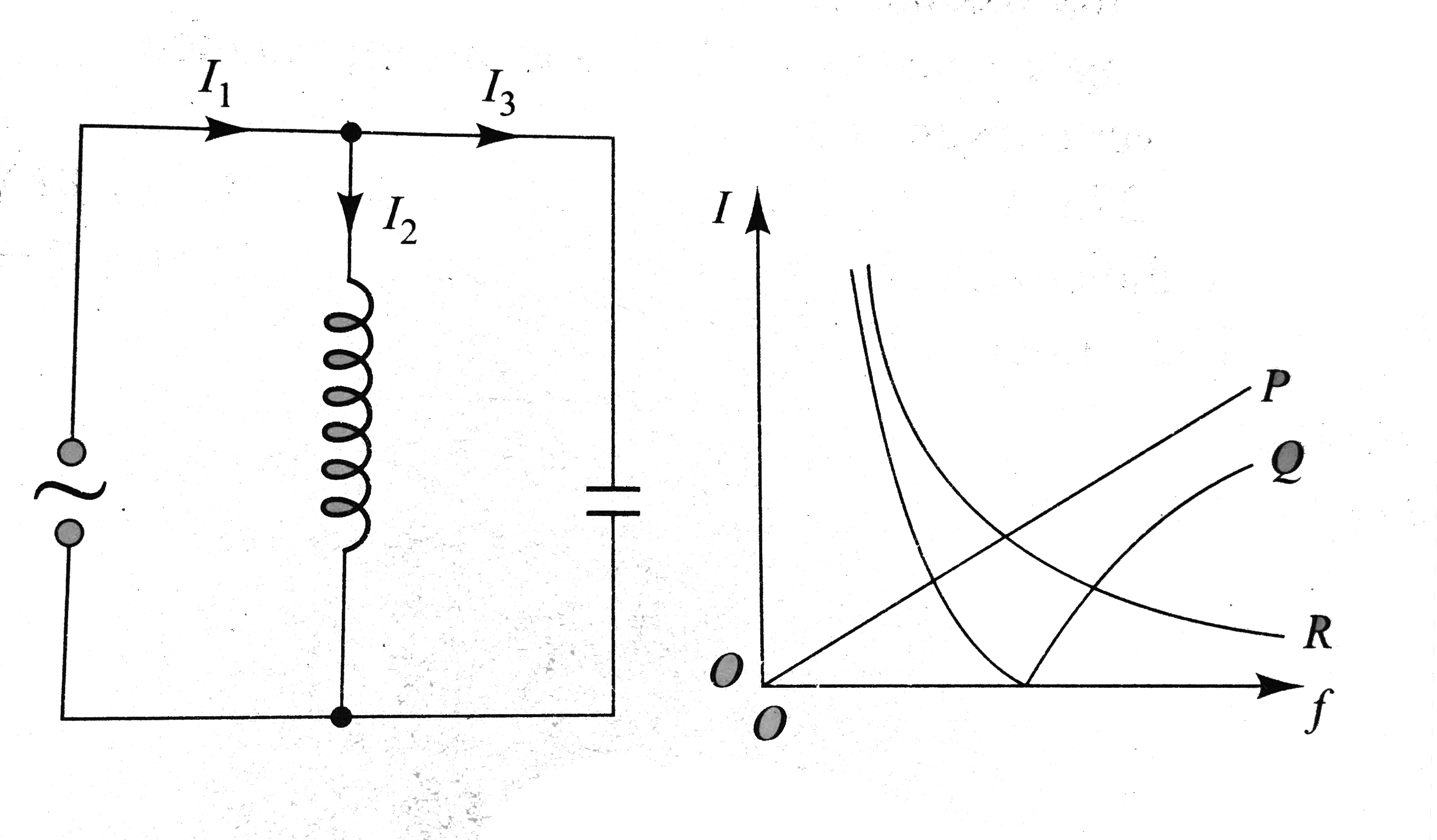
View SolutionIn the circuit shown if fig, the rims currents `(I_1), (I_2)` and` (I_3)` are altered by varying the freqency f of the oscillator. The output voltage of the oscillatro remains sinusoidal and has a fixed amplitude.
When curves in figure correctly indicate the variation with frequency of the currents `(I_1), (I_2),and (I_3)`.
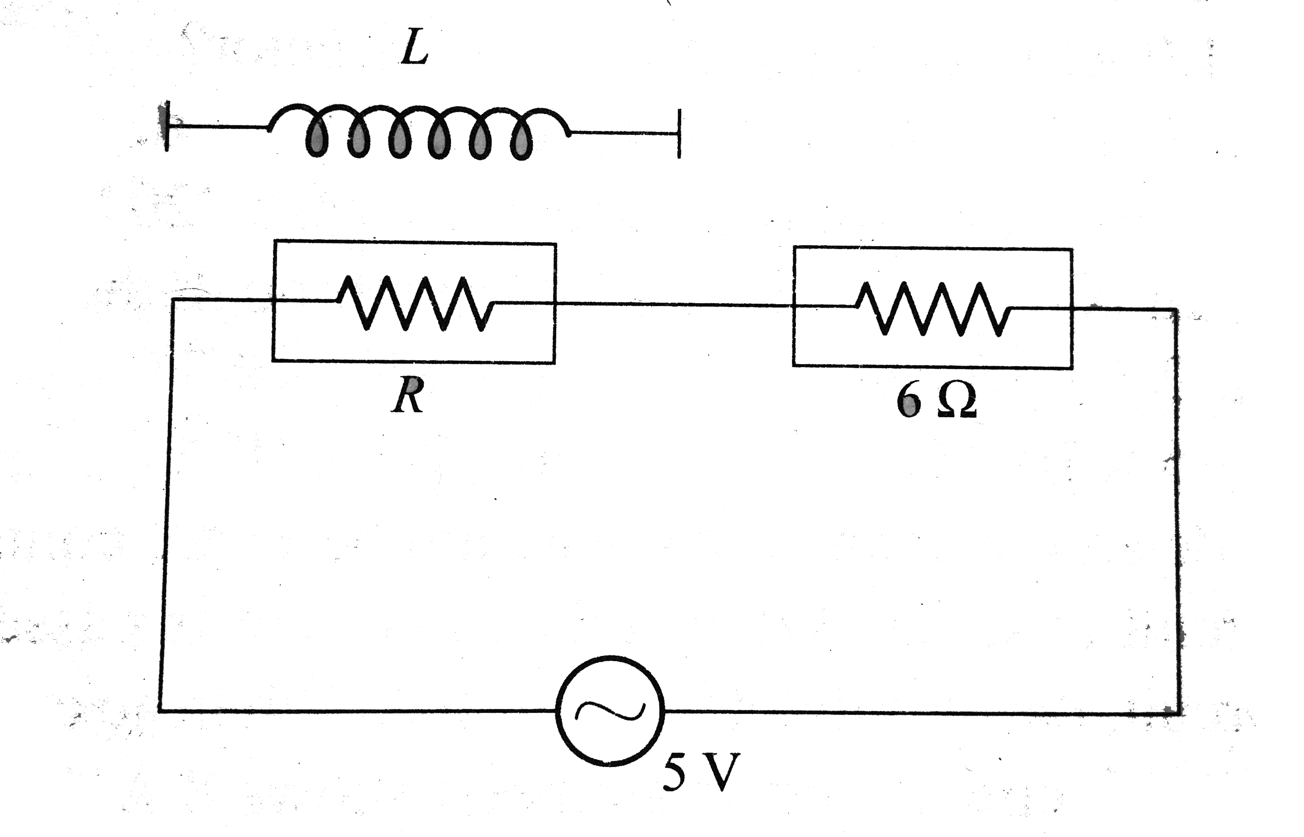
View SolutionTwo resistor are connected in series across a 5 V rms source of alternating potential. The potential difference across `6 Omega` resistor is 3V. If R is replaced by a pure inductor L of such magnitude that current remains same. Then the potential difference across L is
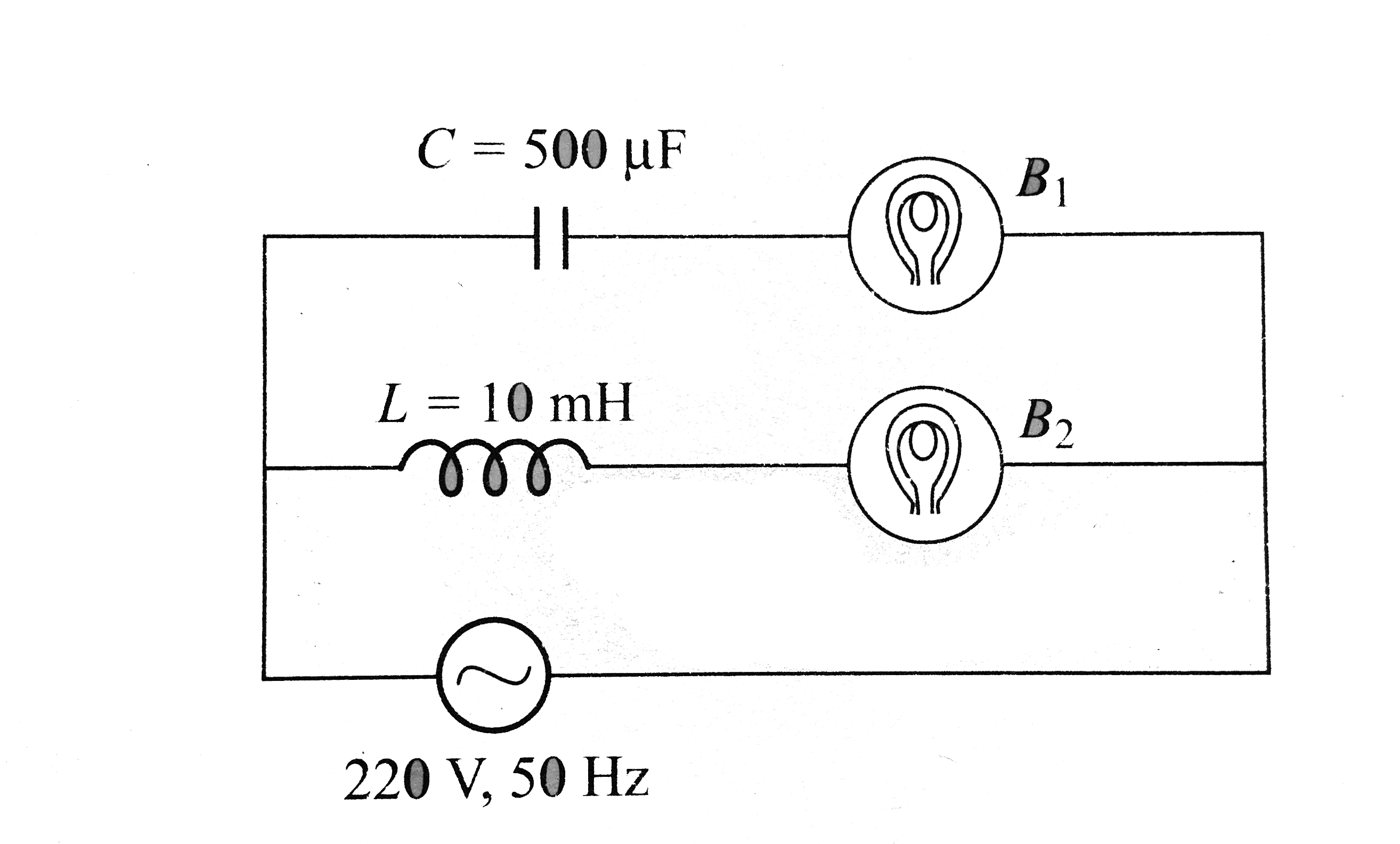
View SolutionIn the circuit shown in fig. if both the bulbs `(B_1) and (B_2)` are identical
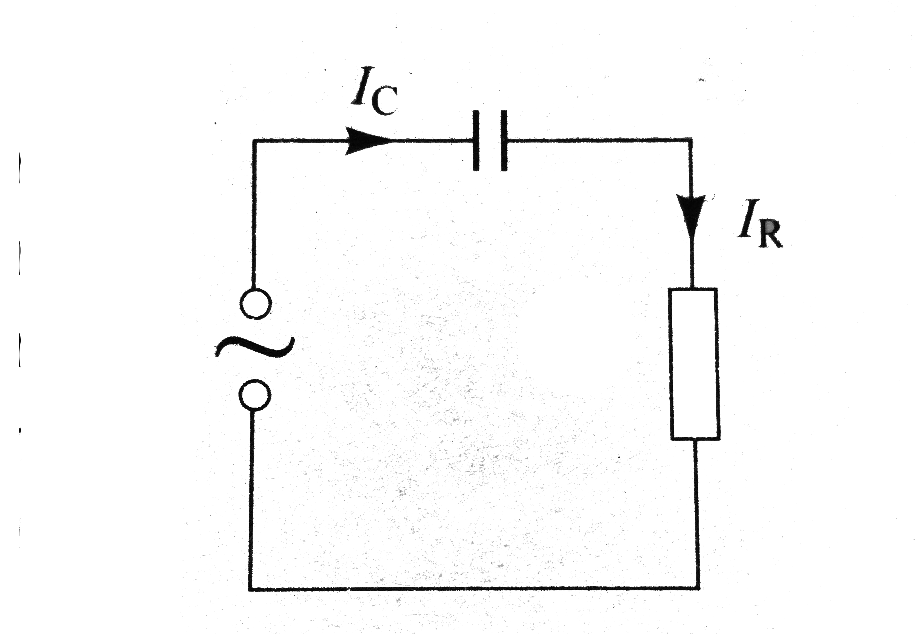
View Solutionfigure, shows a source of alternating voltage connected to a capacitor and a resistor. Which of the following phasor diagrams correctly describes the phase relationship between `(I_C)` the current between the source and the capacitor and `(I_R)` the current in the resistor?
View SolutionA sinusoidal alternating current of peak value `(I_0)` passes through a heater of resistance R. What is the mean power output of the heater?
View SolutionPower factor is one for
View SolutionA resonance of `20 Omega` is connected to a source of an alternating potential `V=220 sin (100 pi t)`. The time taken by the current to change from the peak value to rms value is
View SolutionIn LCR circuit currnet resonant frequency is 600Hz and half power points are at 650 and 550 Hz. The quality factor is
View SolutionAn ac voltage is represented by
`E=220 sqrt(2) cos (50 pi) t`
How many times will the current become zero in 1 s?
View SolutionA resistor and an inductor are connected to an ac supply of 120 V and 50 Hz, the current in the circuit is 3 A. If the power consumed in the circuit is 108 W, then the resistance in the circuit is
View SolutionA transmitter transmits at a wavelength of 300 m. A condenser of capacitance `2.4 (mu)F` is being used. The value of the inductance for the resonant circuit is approximatly
View SolutionA capasitor of capacitance `1 (mu)F` is charged to a potential of 1 V, it is connected in parallel to an inductor of inductance `10^(-3)H`. The maximum current that will flow in the circuit has the value
View SolutionUsing an ac voltmeter, the potential difference in the electrical line in a house is read to be 234 V. If the line freqency is known to be 50 cycles per second, the equation for the line voltage is
View SolutionAn inductor and a resistor are connected in series with an ac source. In this circuit.
View SolutionA resistor and a capacitor are connected to an ac supply of 200 V, 50 Hz, in series. The current in the circuit is 2A. If the power consumed in the circuit is 100 W then the resistance in the circuit is
View SolutionIn the above question, the capacitive reactance in the circuit is
View SolutionIn the above question, the capacitance in the circuit is
View SolutionIn a series LCR circuit, the voltage across the resistance, capactiance and inductance is 10 V each. If the capacitance is short circuited, the voltage across the inductance will be
View SolutionAn ideal choke takes a current of 10 A when connected to an ac supply of 125 V and 50 Hz. A pure resistor under the same conditions takes a current of 12.5 A. If the two are connected to an ac supply of 100 V and 40 Hz, then the current in series combination of above resistor and inductor is
View SolutionA direct current of `5` amp is superimposed on an alternating current `I=10 sin omega t` flowing through a wire. The effective value of the resulting current will be:
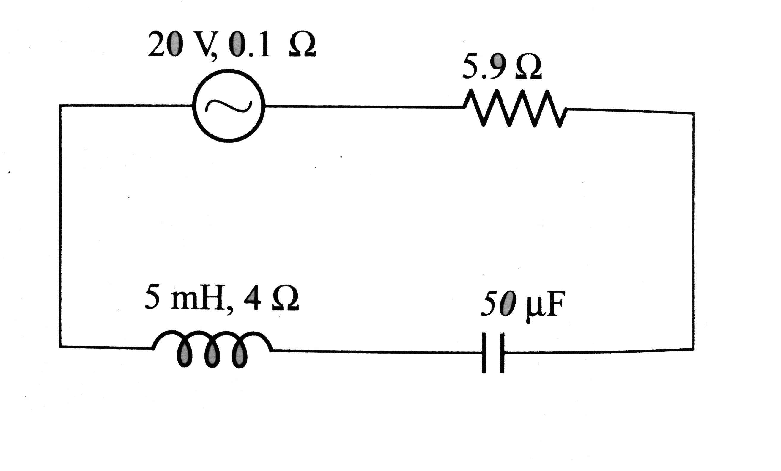
View SolutionIn the circuit of fig, the source freqency is `omega=2000 rad s^(-1)`. The current in the will be
View SolutionAn rms voltage of 110 V is applied across a series circuit having a resistnce `11 Omega` and an impedance `22 Omega`. The power consumed is
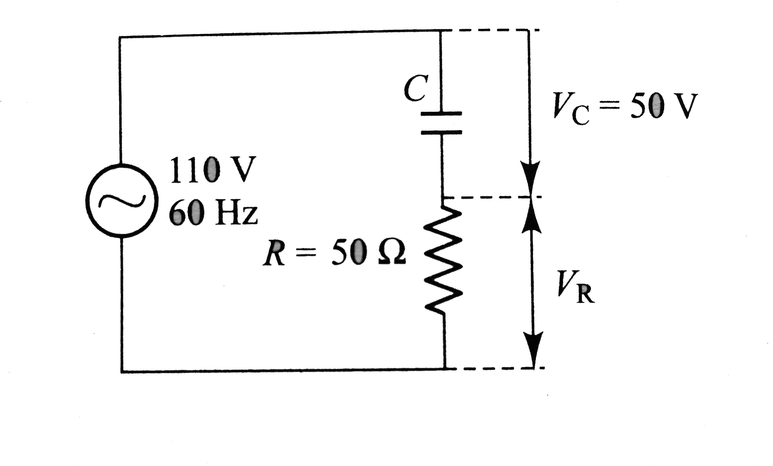
View SolutionIn the circuit given in fig. `(V_C)=50 V and R=50 Omega`. The values of C and `(V_R)` are
View SolutionA 220-V, 50 Hz, ac generator is connected to an inductor and a `50 Omega` resistance in series. The current in the circuit is `1.0 A`. What is the PD across inductor?
View SolutionAn `8 (mu)F` capacitor is connected across a 220 V, 50 Hz line. What is the peak value of charge through the capacitor?
View SolutionA dc ammeter and a hot wire ammeter are connected to a circuit in series. When a direct current is passed through circuit, the dc ammeter shows 6 A. When ac current flows through circuit, the ac ammeter shows 8A. What will be reading of each ammeter if dc and ac current flow simulataneously through the circuit?
View SolutionAn alternating current is given by
`I = i_1 cos omegat + i_2 sin omegat`.
The rms current is given by
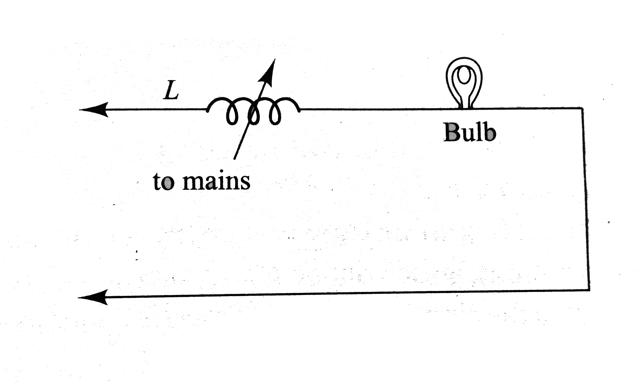
View SolutionA typical light dimmer used to dim the stage lights in a theater consists of a variable induction for L (where inductance is adjustable between zero and `L_(max)`) connected in series with a light bulb B as shown in fig. the mains electrical supply is 220 V at 50 Hz, the light bulb is rated at 220 V, 1100 W. What `(L_(max))` is required if the rate of energy dissipated in the light blub is to be varied by a factor of 5 from its upper limits of 1100 W?
View SolutionTwo alternating voltage generators produce emfs of the same amplitude`(E_0)` but with a phase difference of `(pi)//3`. The resultant emf is
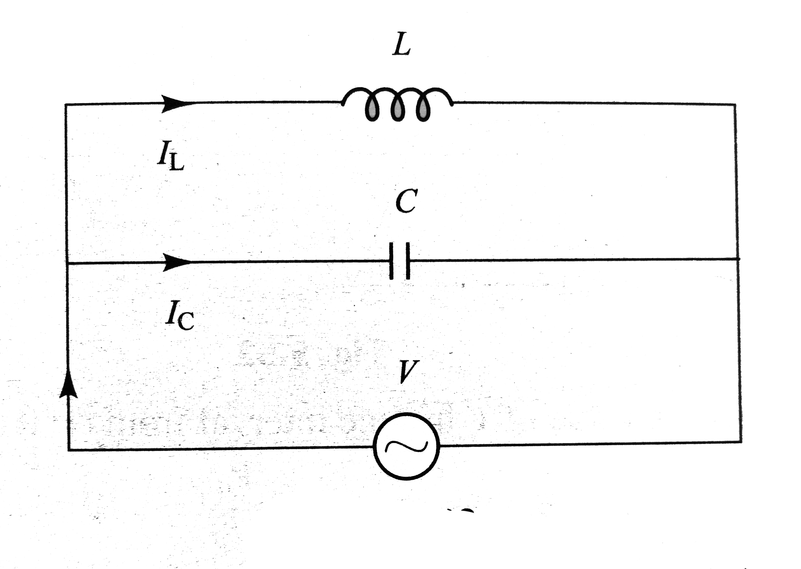
View SolutionFor the circuit shown in fig, current in inductance is 0.8A while that in capacitance is 0.6 A. What is the current drawn from the source?
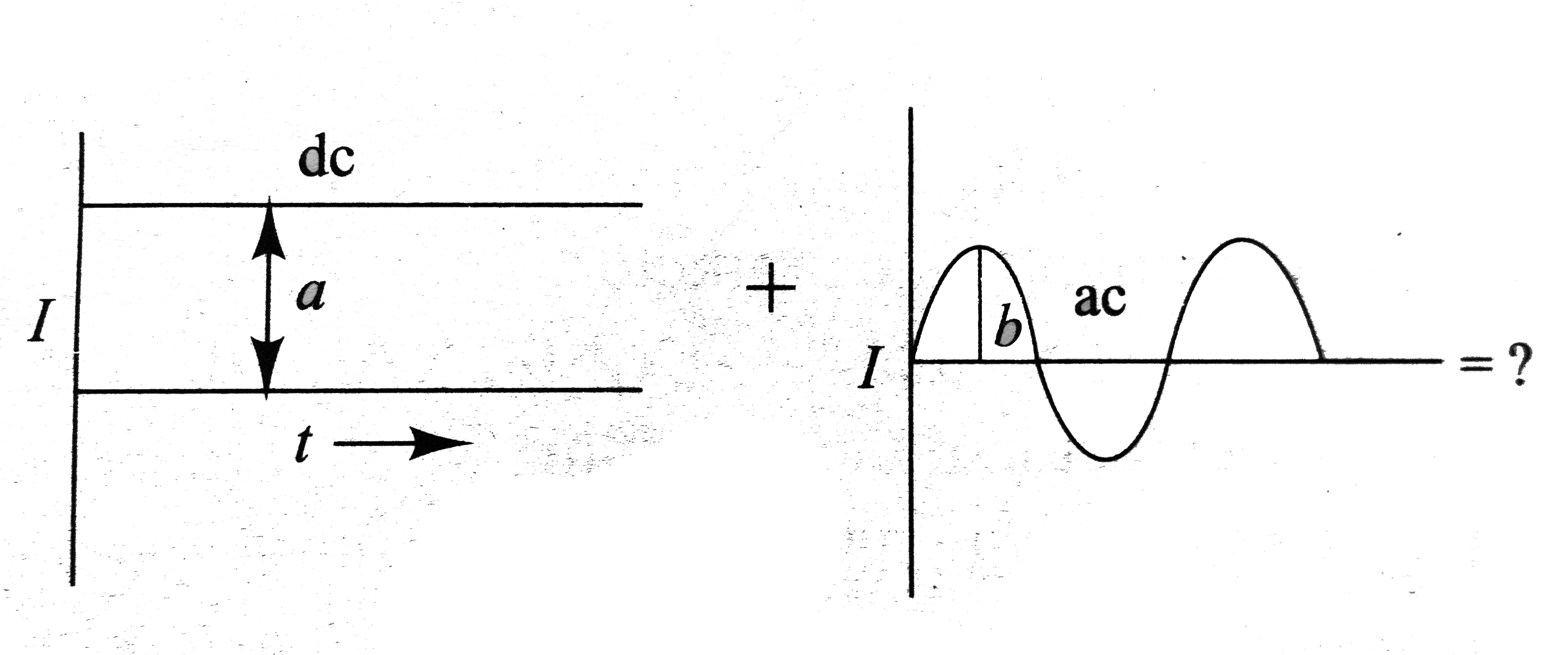
View SolutionIf a direct current of value a ampere is superimposed on an alternative current I=b `sin omega t` flowing through a wire, what is the effective value of the resulting current in the circuit?
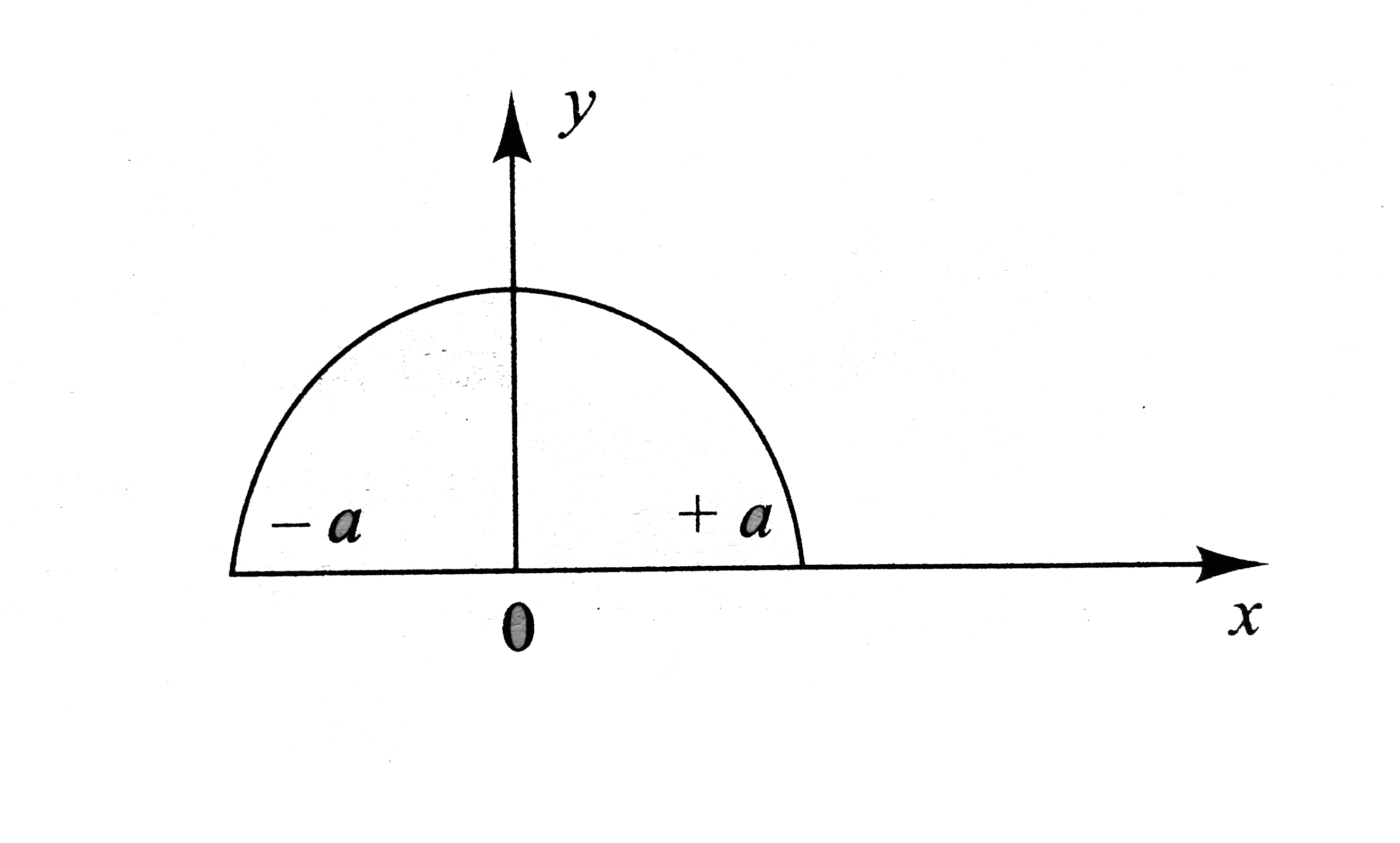
View SolutionDetermine the rms value of a semi-circular current wave which has a maximum value of a.
View SolutionAn alternating voltage `E=200sqrt(2) sin (100 t)V` is connected to a `1 (mu)F` capaacitor through an ac ammeter (it reads rms value). What will be the reading of he ammeter?
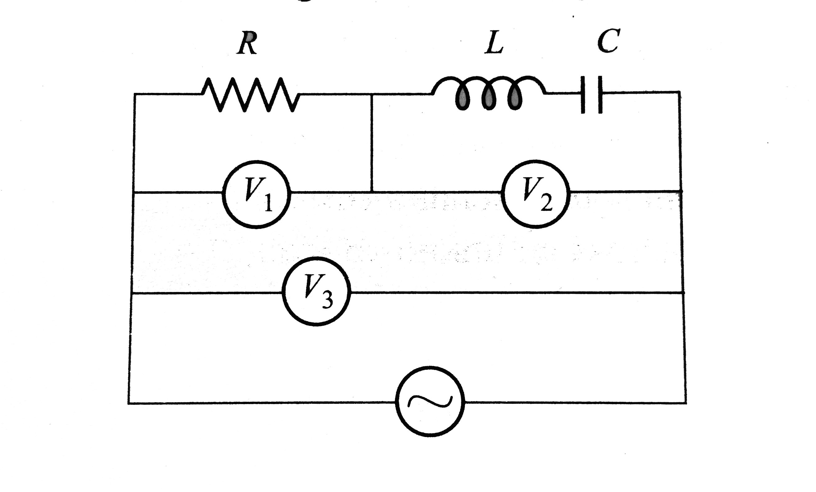
View SolutionWhich voltmeter will give zero reading at resonance?
View SolutionA 50 W, 100V lamp is to be connected to an ac mains of 200V, 50 Hz. What capacitor is essential to be put in series with the lamp?
View SolutionA capacitor of `10 (mu)F` and an inductor of 1 H are joined in series. An ac of 50 Hz is applied to this combination. What is the impedance of the combination?
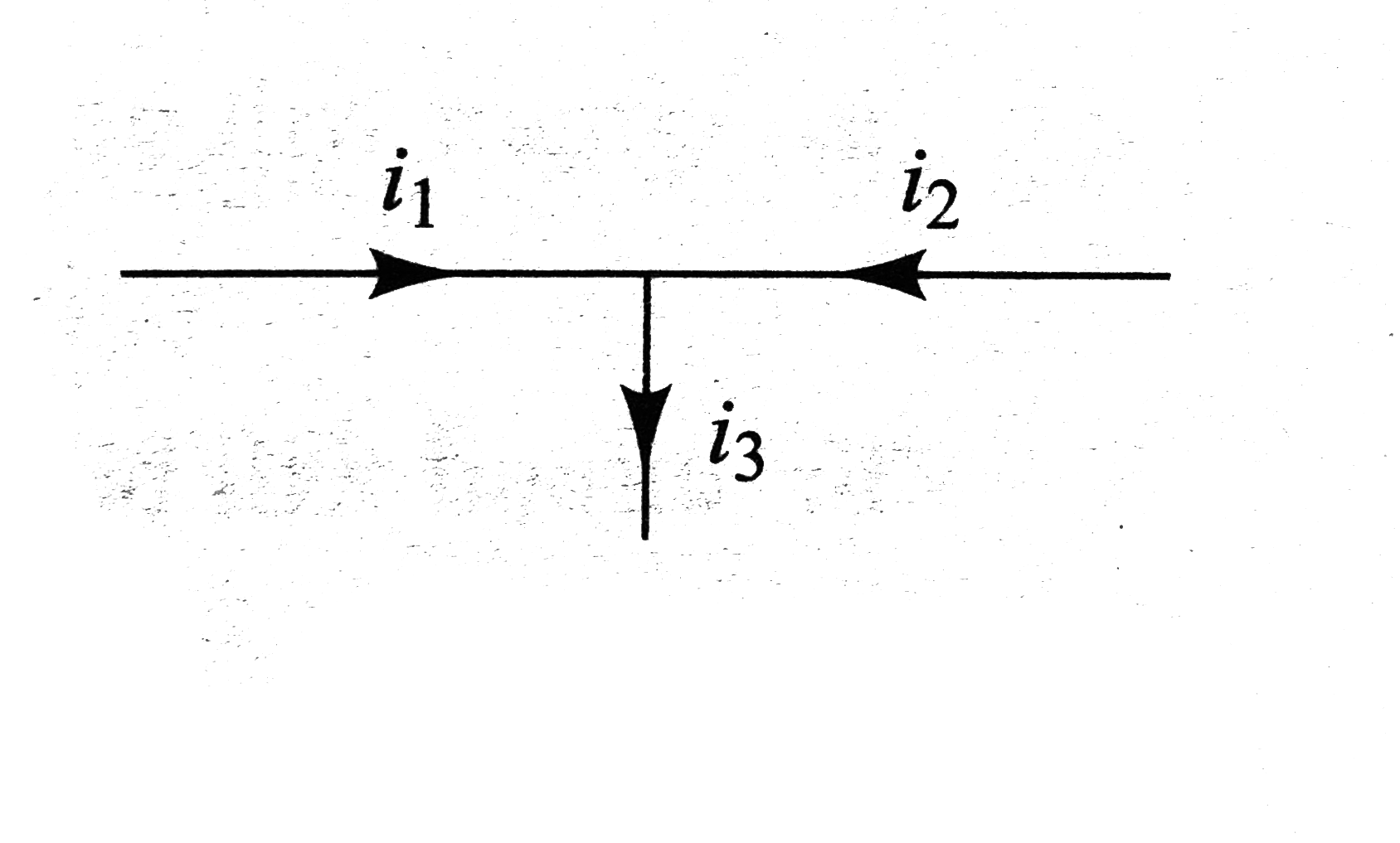
View SolutionIf `i_(1)=3 sin omega t and (i_2) = 4 cos omega t,` then `(i_3)` is
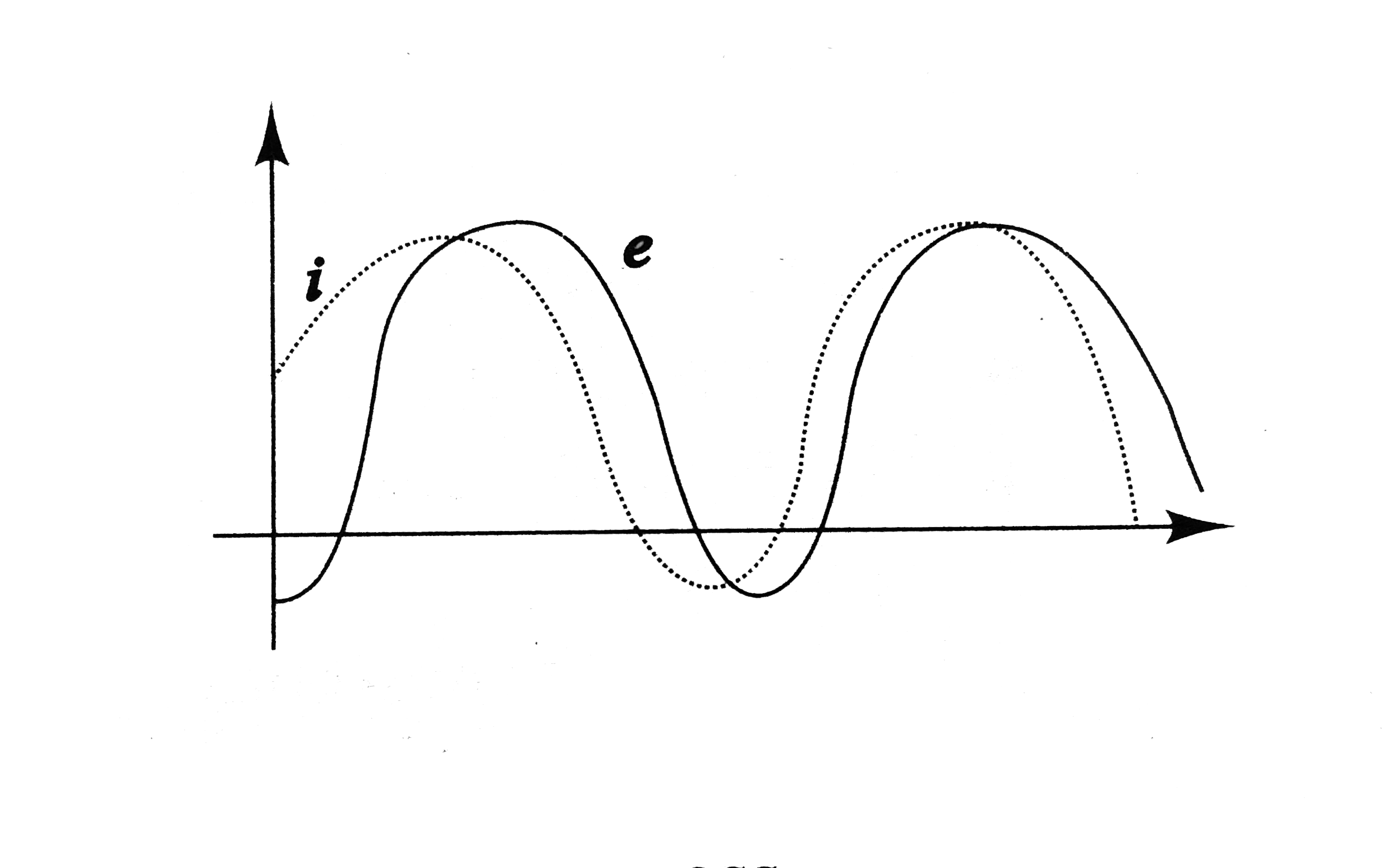
View SolutionWhen an ac source of emf`e=E_(0) sin (100 t)` is connected across a circuit, the phase difference between emf e and currnet I in the circuit is observed to be `(pi)//(4)` as shown in fig. If the circuit consists possibly only of R-C or R-C of L-R series, find the relationship find the relationship between the two elements.
View SolutionIn an ac circuit the potential differences across an inductance and resistance joined in series are, respectively, 16 V and 20 V. The total potential difference across the circuit is
View SolutionCurrent in an ac circuit is given by `I= 3 sin omega t + 4 cos omega t, ` then
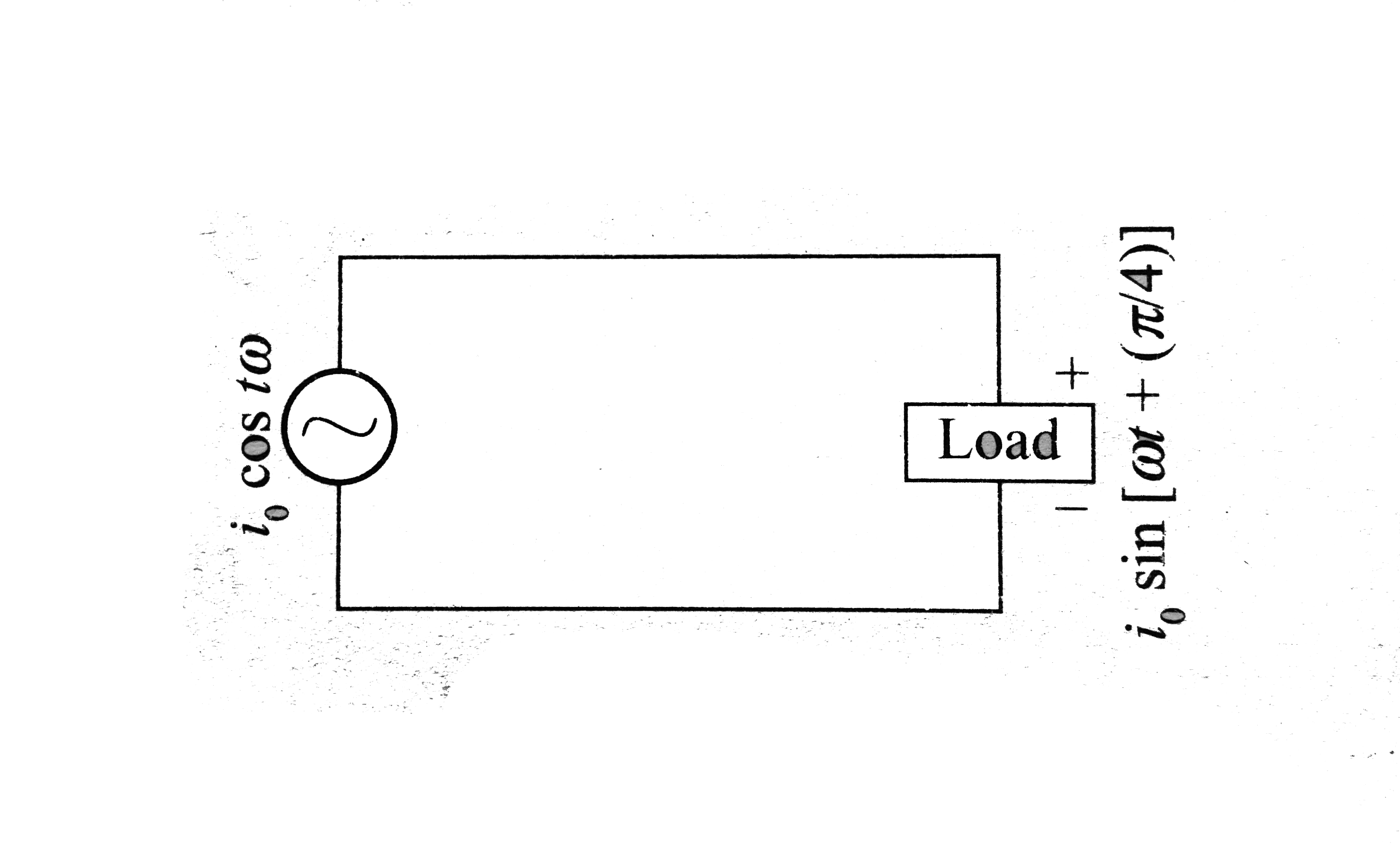
View SolutionA current source sends a current `I=(i_0) cos (omegat)`, When connected across an unknown load, it gives a voltages output of `v=v_(0)sin [omega t+(pi//4)]` across that load. Then the voltage across the current source may bebroaught in phase with the current through it by
View SolutionIn the circuit shown in fig. `X_(C ) = 100 Omega,(X_L)=200 Omega and R=100 Omega`. The effective current through the source is
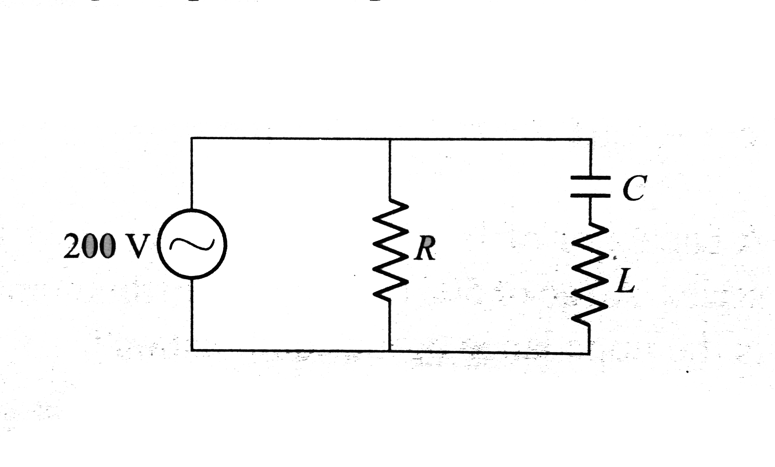
View SolutionFor an LCR series circuit with an aac source of angular frequency `omega`.
View SolutionThe value of current in tow series LCR circuits at resonance is same, then
View SolutionIn series LCR circuit voltage drop across resistance is 8V, across inductor is 6V and across capacitor is 12V. Then
View SolutionIn a black box of unknown elements (L or R or any other combination), an ac voltage `E=E_(0) sin (omegat)+phi)` is applied and current in the circuit was found to be `I=I_0` sin [ omega t + phi + (pi//4)]`. Then the unknown elements in the box may be
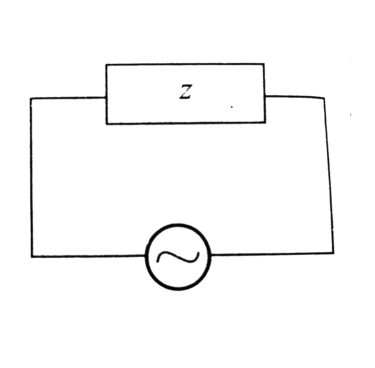
View SolutionThe voltage time (V-t) graoh for triangular wave having peak value `(V_0)` is as shown in fig.
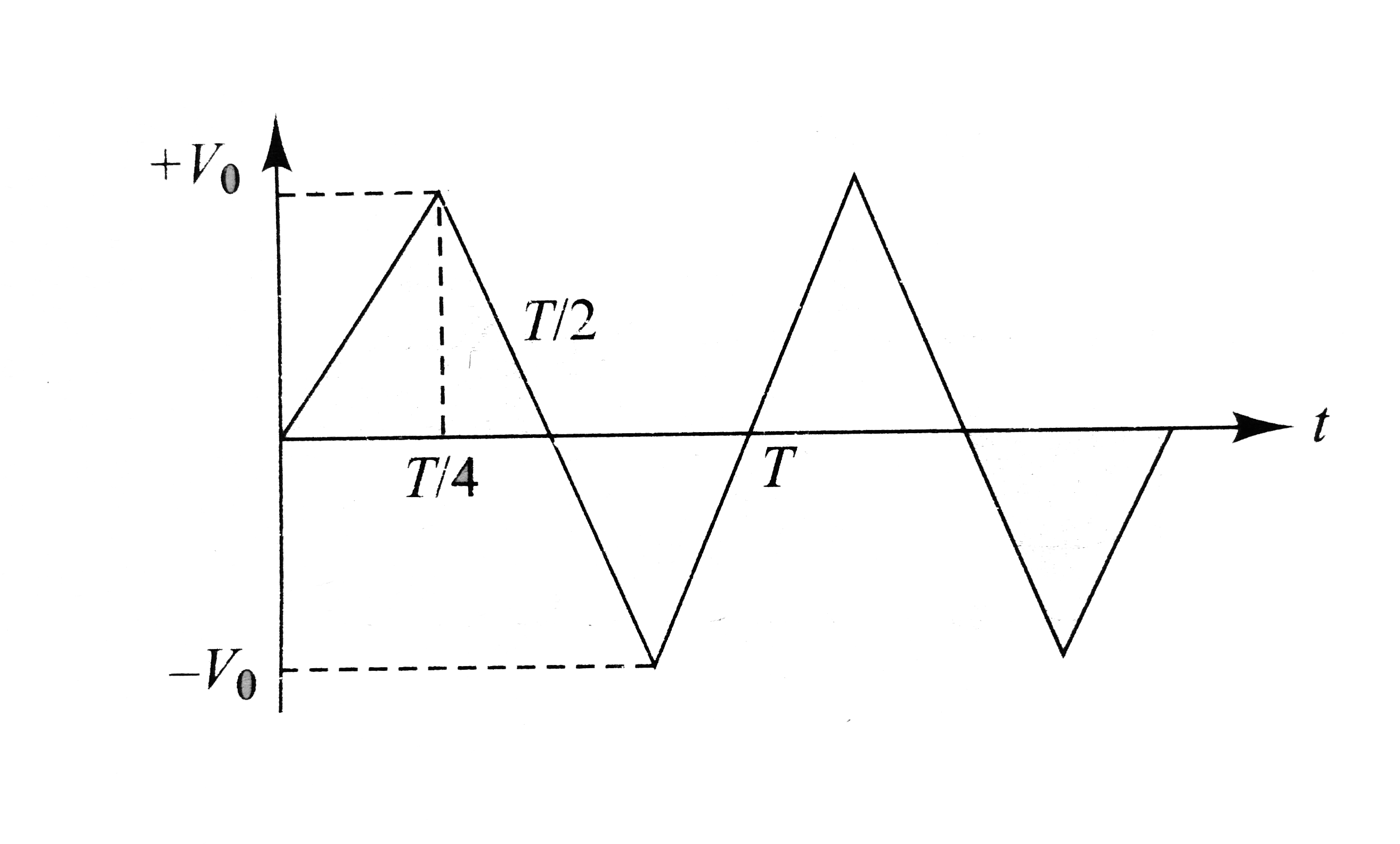
View SolutionIn the above question, the average value of voltage (V) in one time period will be
View SolutionWhat reading would you expact of a square-wave current, suitching rapodly between +0.5 A and -0.5 A, when passed through an ac ammeter?
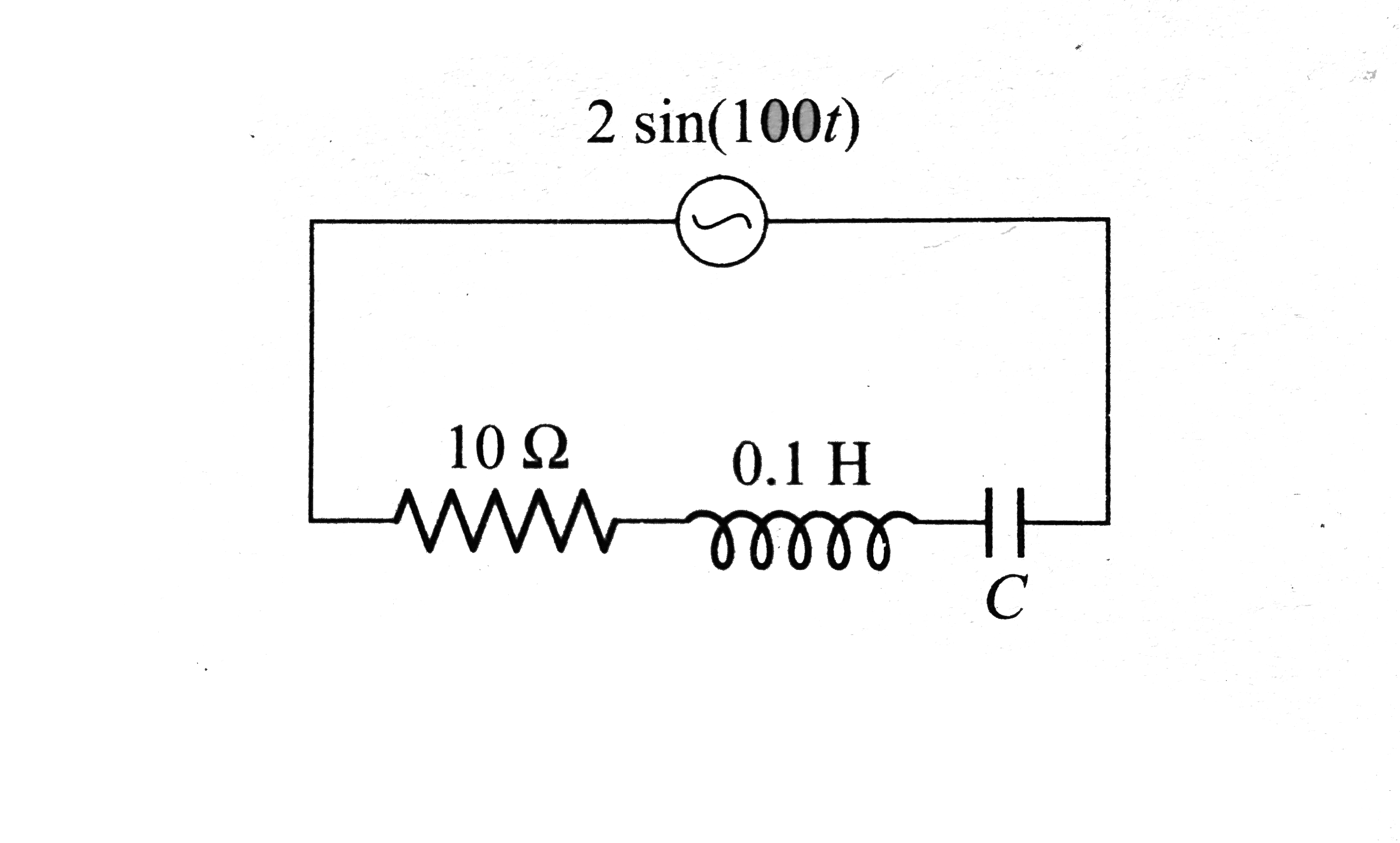
View SolutionThe power factor of the circuit in fig. is `1//sqrt(2)`. The capacitance of the circuit is equal to
View SolutionIn an ideal transformer, the voltagae and the current in the primary coil are 200V and 2 A, respectively. If the voltage in the secondary coil is 200 V, then the value of current in the secondary coil will be
View Solution
Exercises Single Correct questions and complete solutions for chapter ALTERNATING CURRENT of CENGAGE PHYSICS (HINGLISH) of Class 12
All Exercises from CENGAGE PHYSICS Class 12 PHYSICS ALTERNATING CURRENT
- Archives Integer
- Archives Multiple Correct
- Archives Single Correct
- Archives Subjective
- Comphension Based
- Exercise 5.1
- Exercises Assertion-reasoning
- Exercises Integer
- Exercises Linked Comprehension
- Exercises Multiple Correct
- Exercises Single Correct
- Exercises Subjective
- Illustrations
- QUESTION BANK
- Single Correct
- Single Correct Asnwer Type
- Solved Examples