Complete Solutions to All Questions of chapter ELECTRIC CURRENT IN CONDUCTORS of Class 12 book with complete answers and questions
| Class 12 | PHYSICS |
| Chapter | ELECTRIC CURRENT IN CONDUCTORS |
| D MUKHERJEE | All Questions |
| Number Of Questions | 79 |
| Academic Year | 2023-24 |
The carrier density (number of free electrons per `m^(3)` ) in metallic conductoirs is of the order of
View SolutionWhen a current flows in a conductor, the order of magnitude of drift velocity of electrons through it is :
View SolutionThe resistance of a metallic conductor increases with temperature due to.
View SolutionA piece of copper and another of germanium are cooled from room temperature to `80 K`. The resistance of
View SolutionA straight conductor of uniform cross-section carries a current `I`. Let `s=` specific charge of an electron. The momentum of all the free electrons per unit length of the conductor, due to their drift velocity only, is
View SolutionCurrent flows through a metallic conductor whose area of cross-section increases in the direction of the current. If we move in this direction.
View SolutionA conducting ring of radius `R` has charge `Q` distributed unevenly over it. If it rotates with an angular velocity `omega`, the equivalent current will be
View SolutionAll the edges of a block with parallel faces are unequal. Its longest edge is twice its shortest edge. The ratio of the maximum to minimum resistance between parallel faces is.
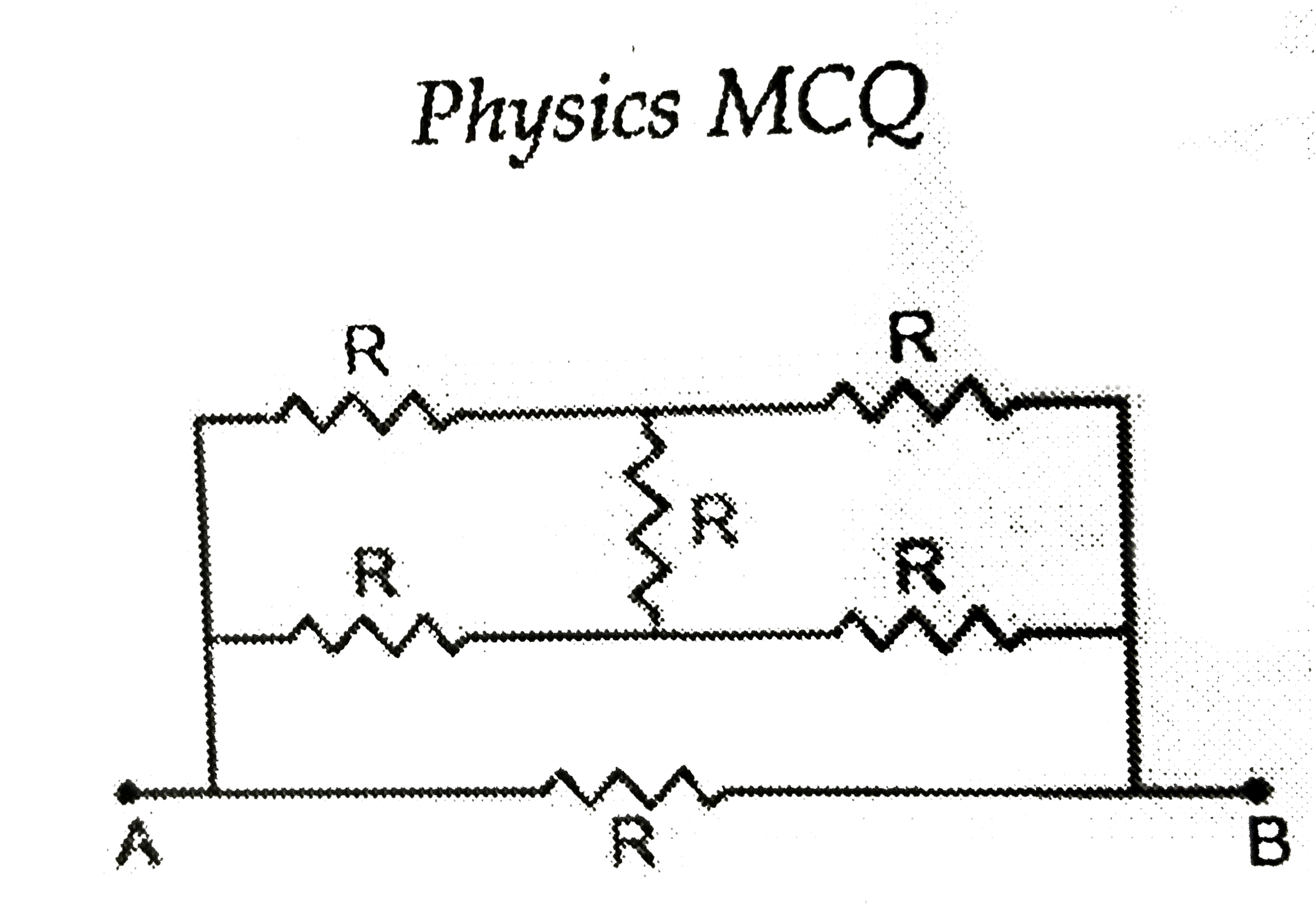
View SolutionIn the network shown below, the equivalent resistance between `A` and `B` is
View Solution`A` and `B` are two points on a uniform ring of resistance `R` the `/_ASCB=theta`, whre `C` is the centre of the sign. The equivalent reisrtance between `A` and `b`
View Solution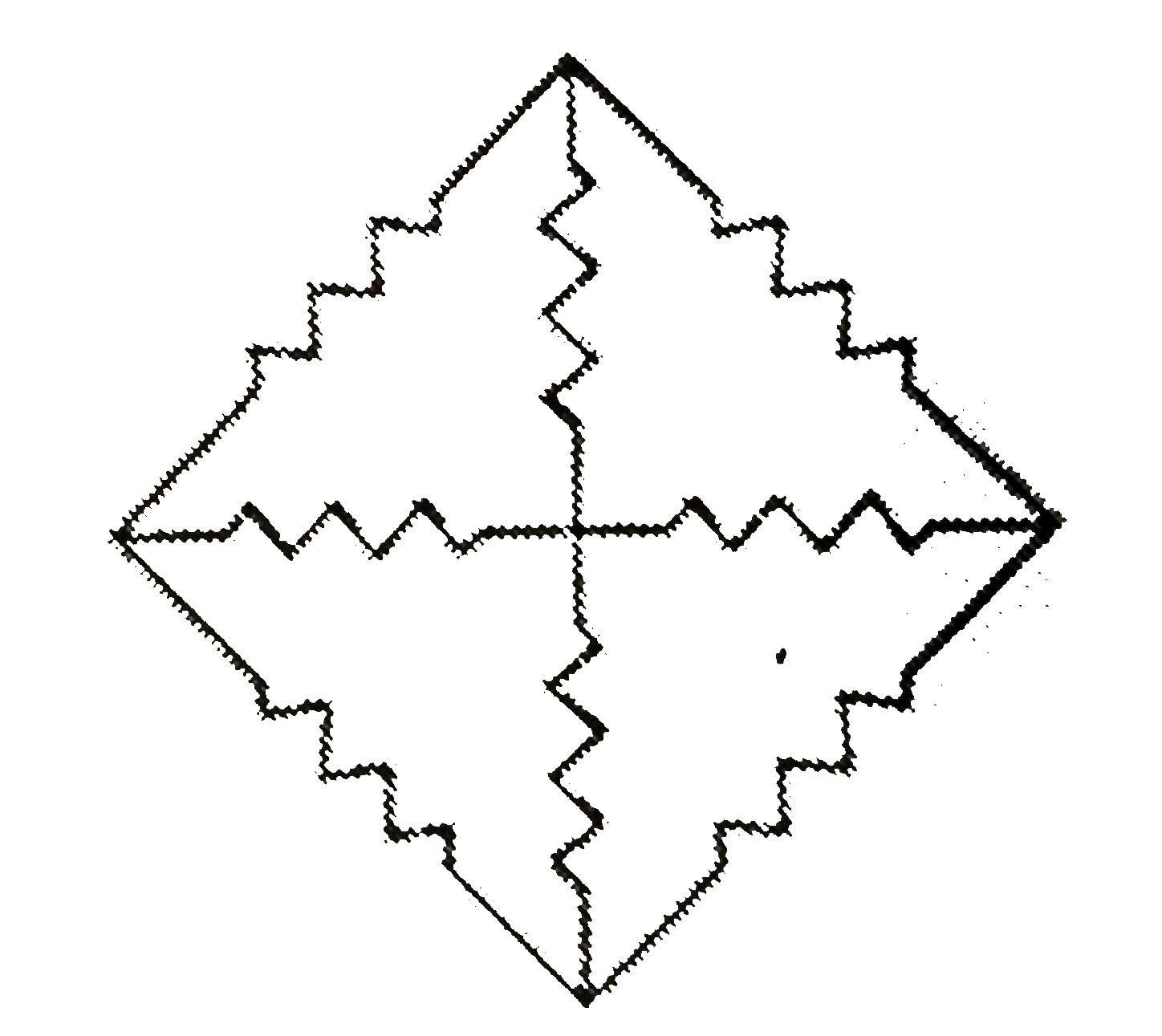
In the network shown, each resistance is equal to `R`. The equivalent resistance between diagonally opposite corners is
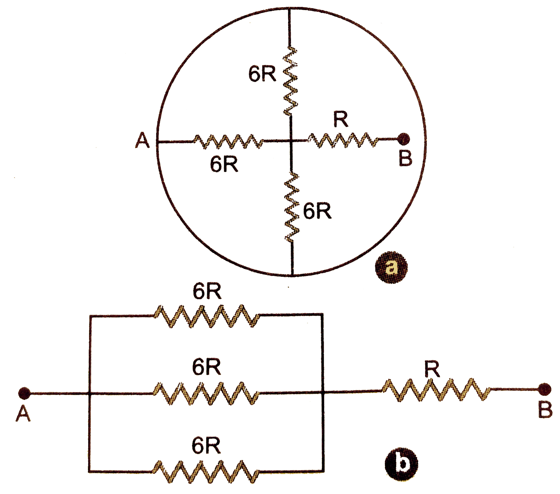
View SolutionIn the network shown in figure, the ring has zero resistance. Find the resistance between A and B.
View SolutionThe two ends of a uniform conductor are joined to a cell of e.m.f. `E` and some internal resistance. Starting from the midpoint `P` of the conductor, we move in the direction of current and return to `P`. The potential `V` at every point on the path is plotted against the distance covered `(x)`. which of the following graphs best represent the resulting curve ?
View SolutionThe emf of a cell is `epsilon` and its internal resistance is r. its terminals are connected to a resistance R. The potential difference between the terminals is `1.6V` for `R = 4 Omega`, and `1.8 V` for `R = 9 Omega`. Then,
View SolutionN identical cells are connected to form a battery. When the terminals of the battery are joined directly (short - circuited), current I flows in the circuit. To obtain the maximum value of I,
View Solution`N` identical cells, each emf `E` and internal resistance `r` are joined in series. Out of `N` cells, `n` cells are wrongly connected i.e., their terminals are connected in reverse of the required for series connection `(n lt (N)/(2))`. Let `E_(0)` be the emf of resulting battery and `r_(0)` be its internal resistance. Then
View Solutionn identical cells, each of emf E and internal resistance r, are joined in series to form a closed circuit. Find the potential difference across any one cell.
View Solutionn identical cells, each of emf `epsilon` and internal resistance r, are joined in series to from a closed circuit. One cell a is joined with reversed polarity. The potential difference across each cell, except A, is
View Solution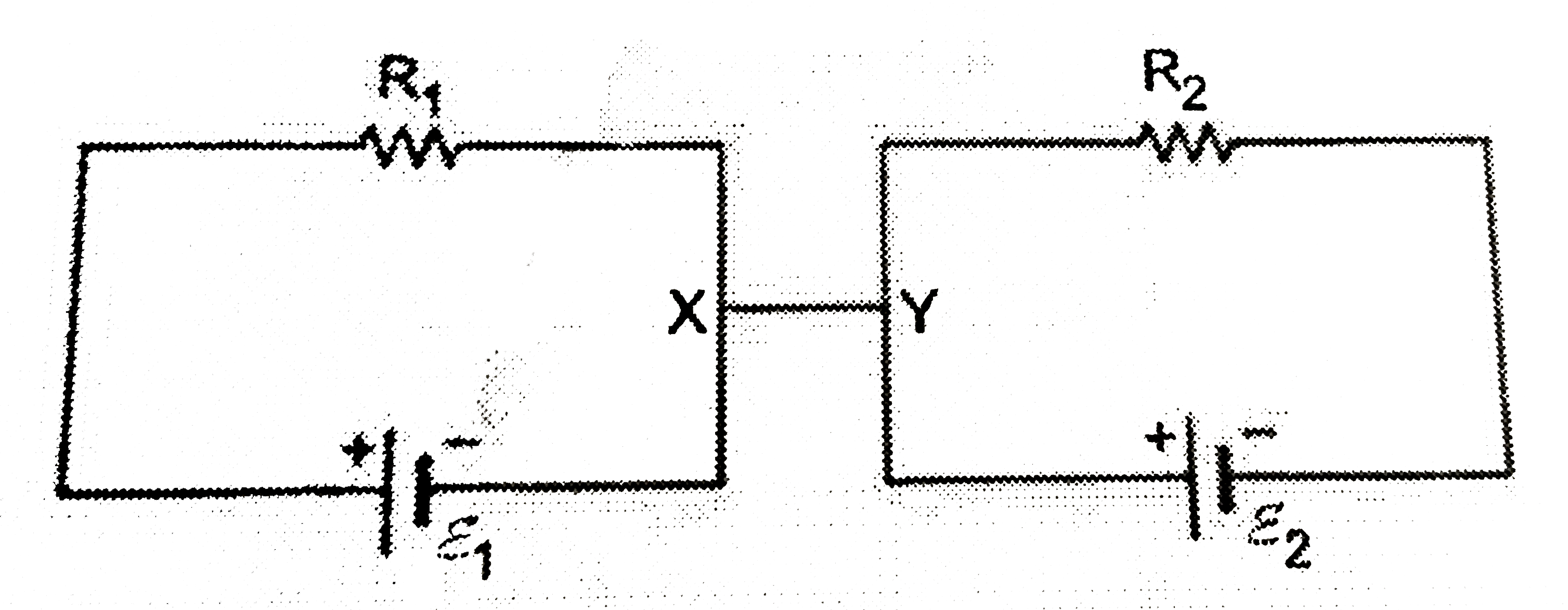
In the circuit shown above, the conductor `XY` is of negligible resisance. Then
View Solution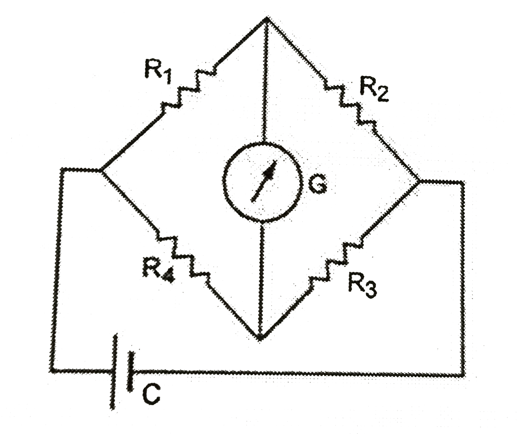
The Wheatstone bridge shown in the above figure is balanced. If the positions of the cell `C` and the galvanometer `G` are now interchanged, `G` will show zero deflection
View Solution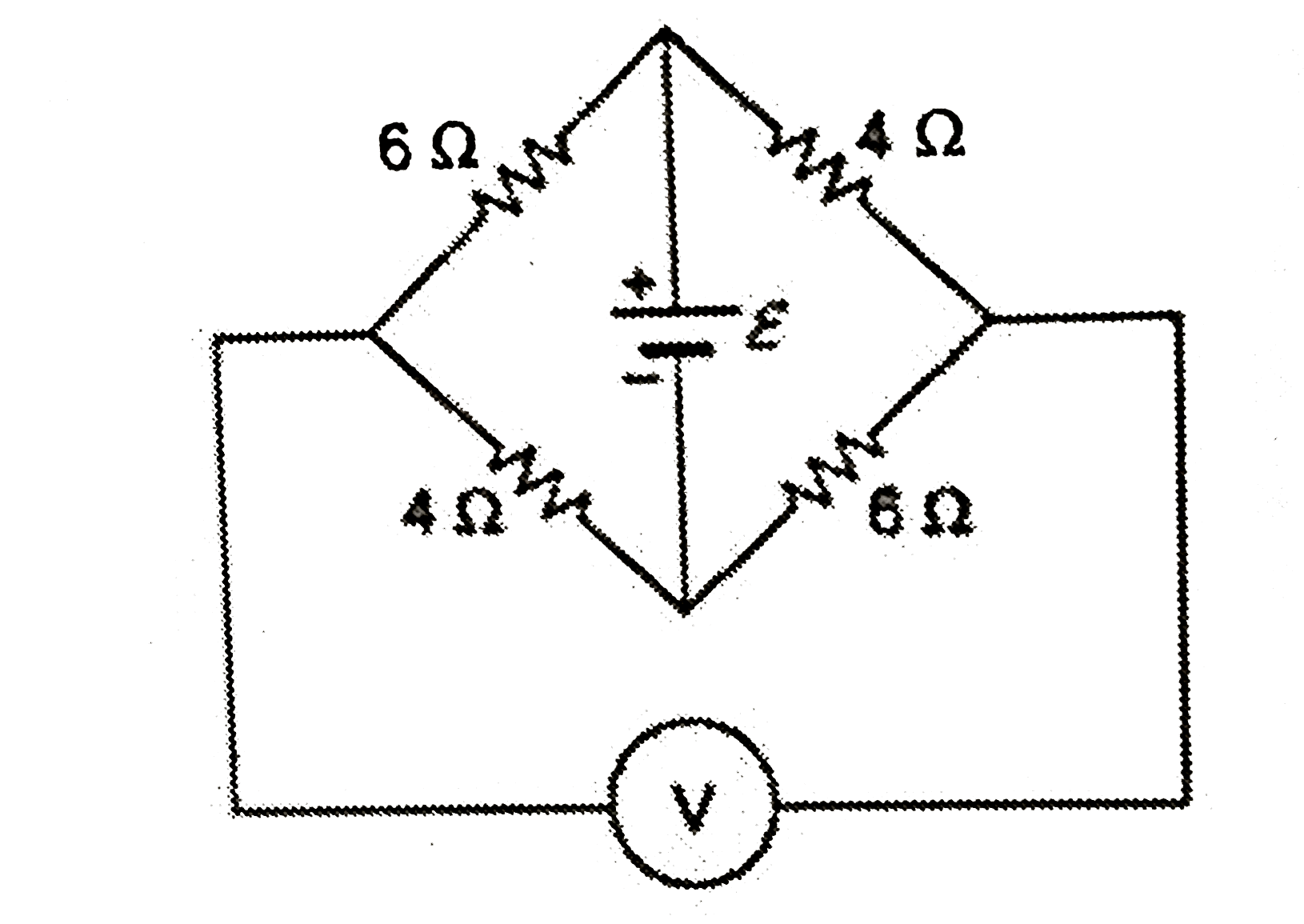
In the circuti shown above the the voltmeter is of large resistance. The emf of the cell is `varepsilon`. The reading of the voltmeter is
View SolutionA Galvanometer of range `10 mA` has a coli of resistance `1 Omega`. To use it as an ammeter of range `1 A`, the required shunt must have a resistance of
View SolutionA milliammeter of range of `10 mA` gives full-scale deflection for a current of `100 mA`, when a shunt of `0.1 Omega` is connected in parallel to it. The coil of the milliammeter has a resistance of.
View Solution`A, B` and `C` are voltmeters of resistances `R, 1.5R` and `3R` respectively. When some potential difference is applied between `x` and `y` the voltmeter readings are `V_A, V`_B`and `V_C,` then
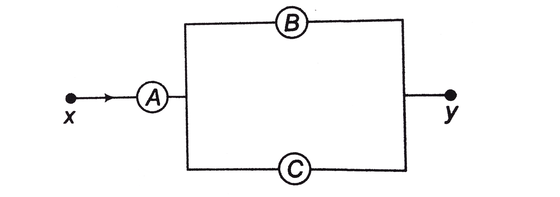
View SolutionAn ammeter and a voltmeter are joined in sereis to a cell. Their readings are `A` and `V` respectively. If a resistance is now joinding parallel with the voltmeter. Then
View SolutionAcell of internal resistance `r` drives a current through an external resistance `R`. The power delivered by the cell to the external resistance is maximum when
View SolutionWhen an electric heater is switched on, the current flowing through it ( i ) is plotted against time ( t ). Taking into account the variation of resistance with temperature, which of the following best represents the resulting curve
View SolutionFigure `7.37` shows a network of three resistances. When some potential difference is applied across the network , thermal powers dissipated by `A, B and C` are in the ratio
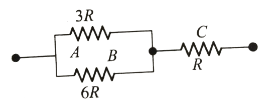
View SolutionAn electric bulb is designed to draw `P_(0)` power at `V_(0)` voltage. If the voltage is `V`, it drawas power. Then
View SolutionAn electric bulb rated for 500 watts at 100 volts is used in a circuit having a 200 volts supply. The resistance R that must be put in series with the bulb, so that the bulb delivers 500 watt is ………ohm.
View SolutionTwo electric bulbs `A` and `B` are designed for the same voltage. Their power ratings are `P_(A)` and `P_(B)` respectively with `P_(A) gt P_(B)` . If they are joined in series across `V` voltage supply
View Solution`n` identical light bulbs, each designed to draw `P` power from a certain voltage supply , are joined in series across that supply. The total power which they will draw is
View SolutionWhen a `500-W` electric and a `500-W` heater operate at their rates voltages, the filament of the bulb reaches a much higher temperature than the filament of the heater. The most important reason for this that
View SolutionA `100W` bulb and a 25W bulb are desigened for the same voltage. They have filaments of the same length and material. The ratio of the diameter of `100W` bulb to that of the `25W` bulb is
View SolutionIf the length of the filament of a heater is reduced by `10%`, the power of the heater will
View SolutionAn ideal cell is connected to a capacitor through a voltmeter. The reading `V` of the voltmeter is plotted agains time. Which of the following best represents the resulting curve?
View SolutionIn the circuit shown in fig. when the switch is closed, the capacitor charges with a time constant
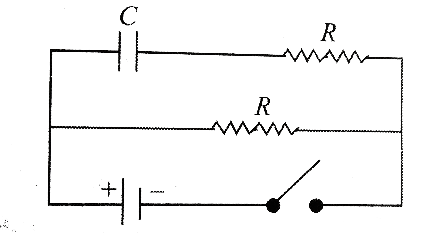
View SolutionA capacitor is charged and then made to discharged through a resistance. The time constant is `tau`. In what time will the potential difference across the capacitor decreases by `10%`?
View SolutionA capacitor charges from a cell through a resistance. The time constant is `tau`. In what time will the capacitor collect `10%` of the final charge?
View SolutionA capacitor of capacitance C has charge Q. it is connected to an identical capacitor through a resistance. The heat produced in the resistance is
View SolutionThe charge on a capacitor decrease `eta` time in time `t`, when it discharging through a circuit with a time constant` tau`
View Solution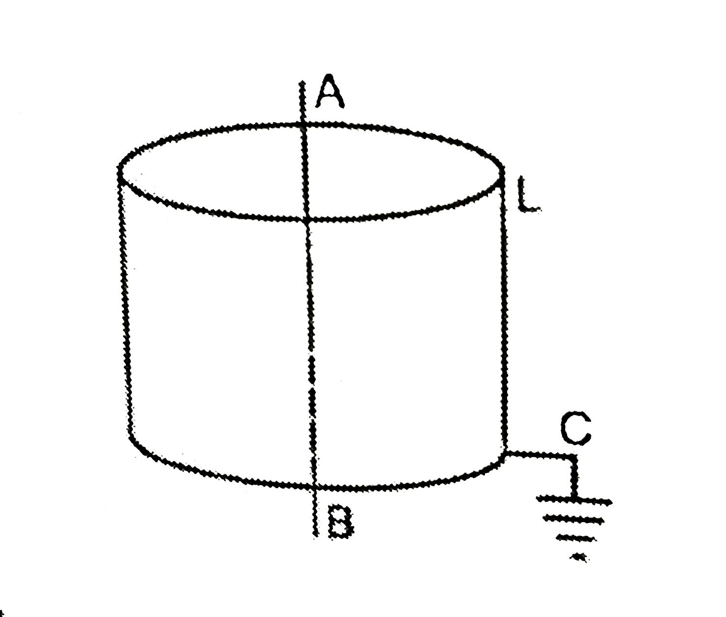
A straight conductor `AB` lies along the axis of a hollow metal cylinder `L`, which is connected to earth through a conductor `C`.A quantity of charge will flow through `C`
View Solution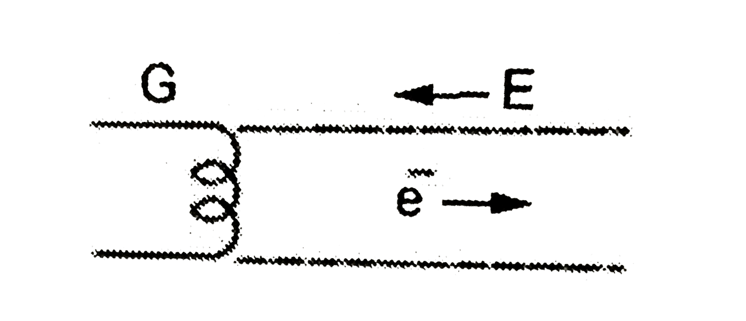
A beam of electorn emitted from the electron gun `G` is accelerated by an electic field `E`. The area of cross-section of the beam remains constant. A the beam moves away from `G`
View SolutionThe charge flowing in a conductor varies with times as `Q = at - bt^2.` Then, the current
View SolutionThe charge flowing in a conductor varies time as,
`q=at - 1/2 bt^(2) +1/6 ct^(3)`
Where a,b,c are positive constants. Then, find (i) the initial current (ii) the time after which the value of current reaches a maximum value (iii) the maximum or minimum value of current.
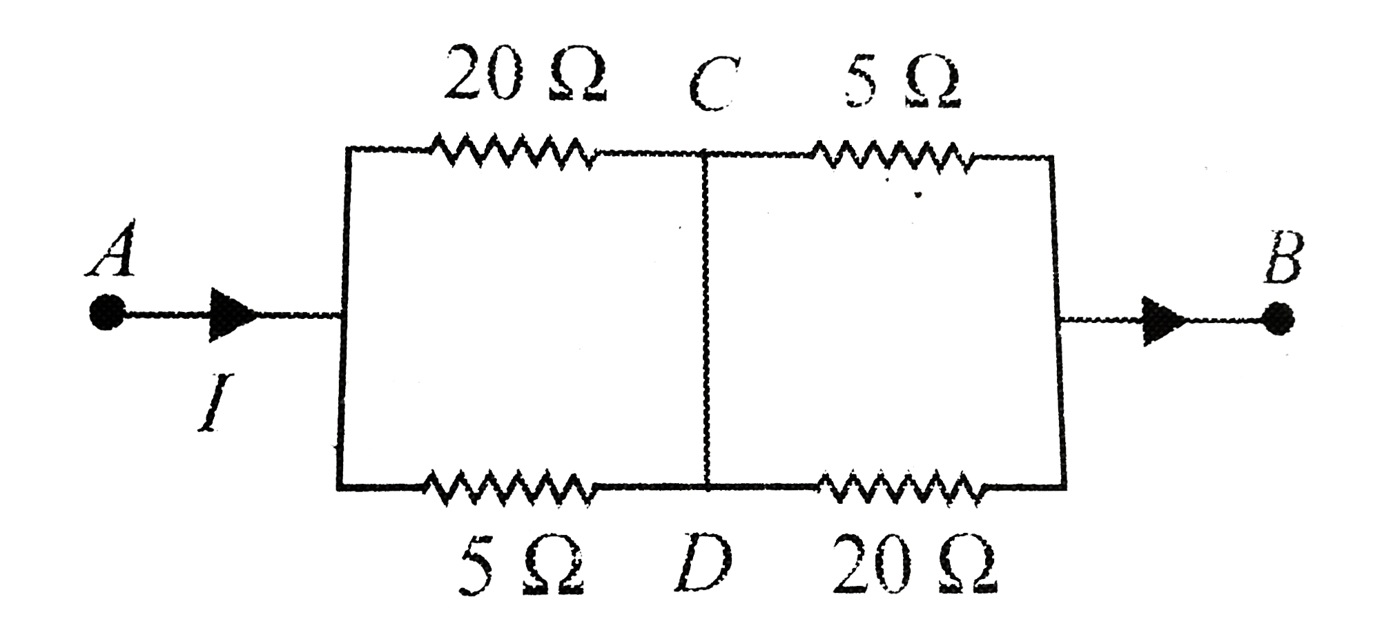
View SolutionWhen some potential differece is maintained between A and B, current I enters the network at A and leaves at B
View Solution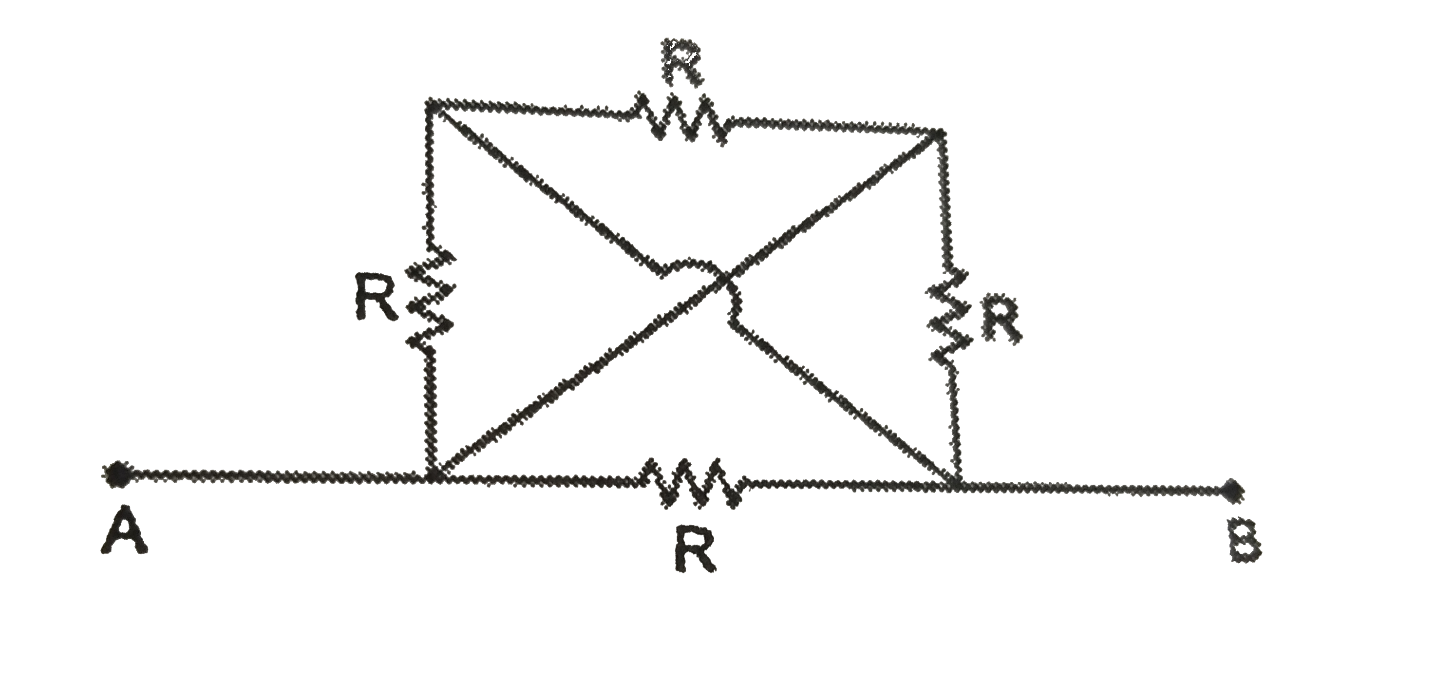
In the circuit shown above, each of the four conductors is of resistance `R`. The potentail difference between `A` and `B` is `V`. The current flowing between `A` and `B` is
View Solution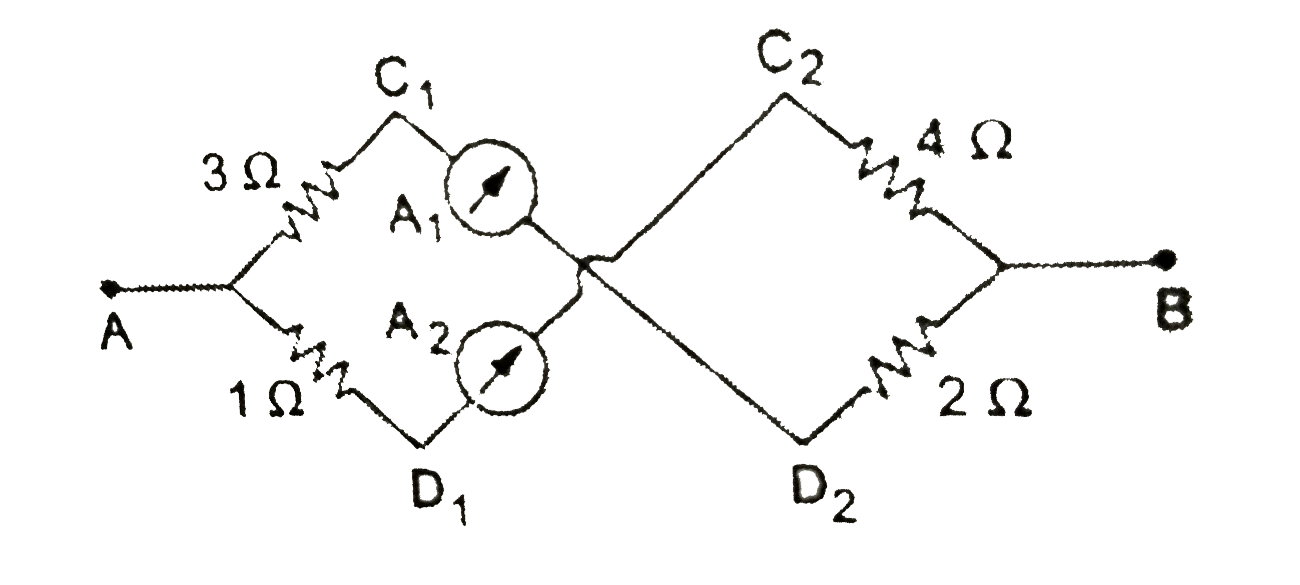
In the circuit shown above, `A_(1)` and `A_(2)` are ammeters of resistance `5Omega` each. When an ideal cell of emf `10V` is applied between `A` and `B`
View Solution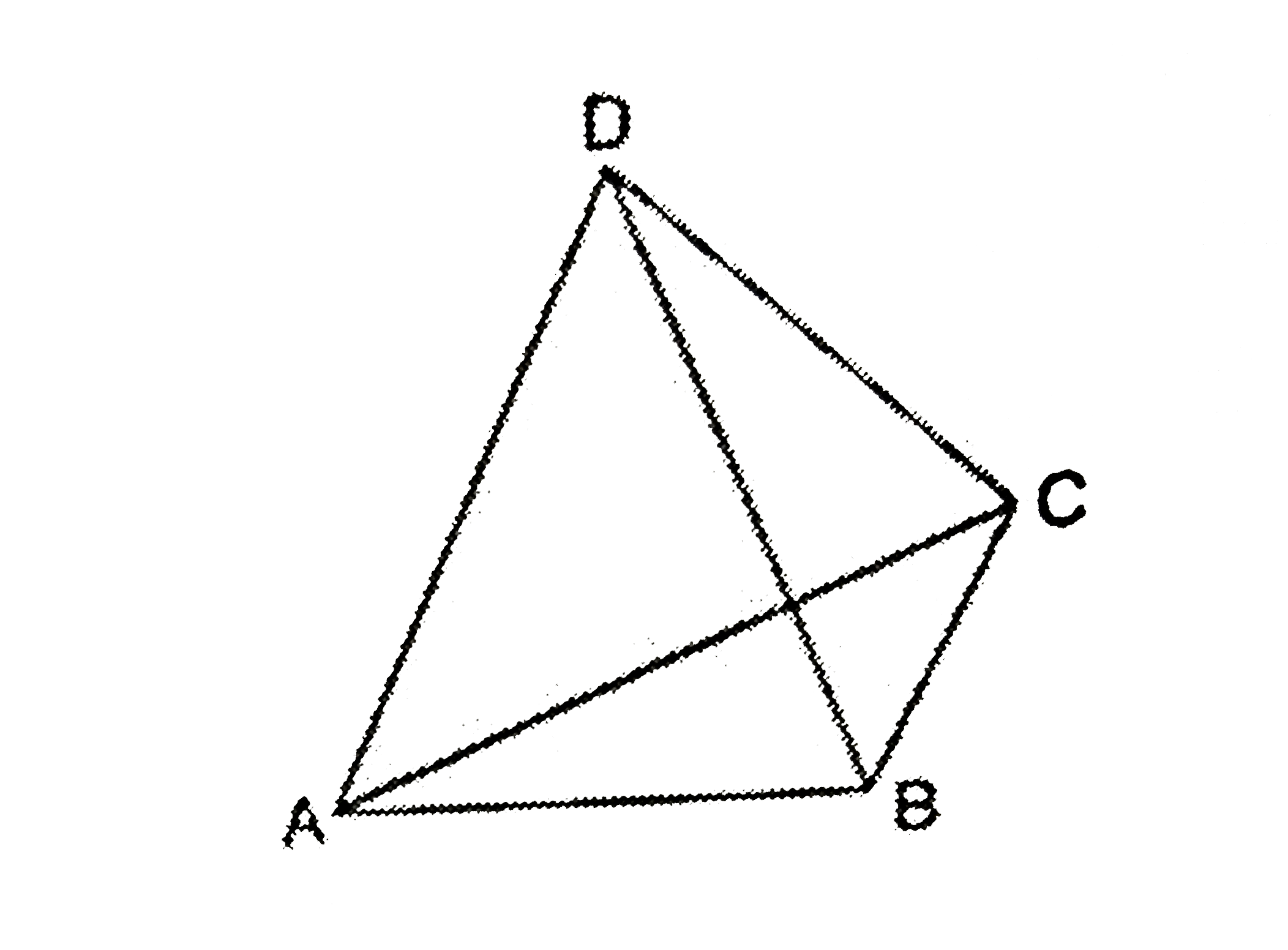
Six identical wires of resistance `R` each are joined to form a pyramid, as shown in the figure above
View Solution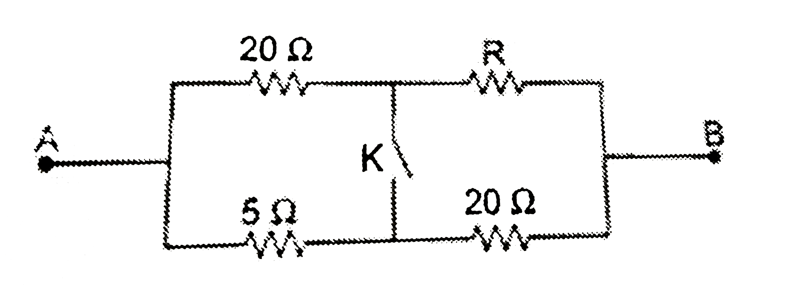
When the switch `K` is open, the equivalent resistance between `A` and `B` is `20Omega`. Then, which is thte correct statemetn?
View SolutionIn the circuit shown in fig. the cell has emf 10V and internal resistance `1 Omega`
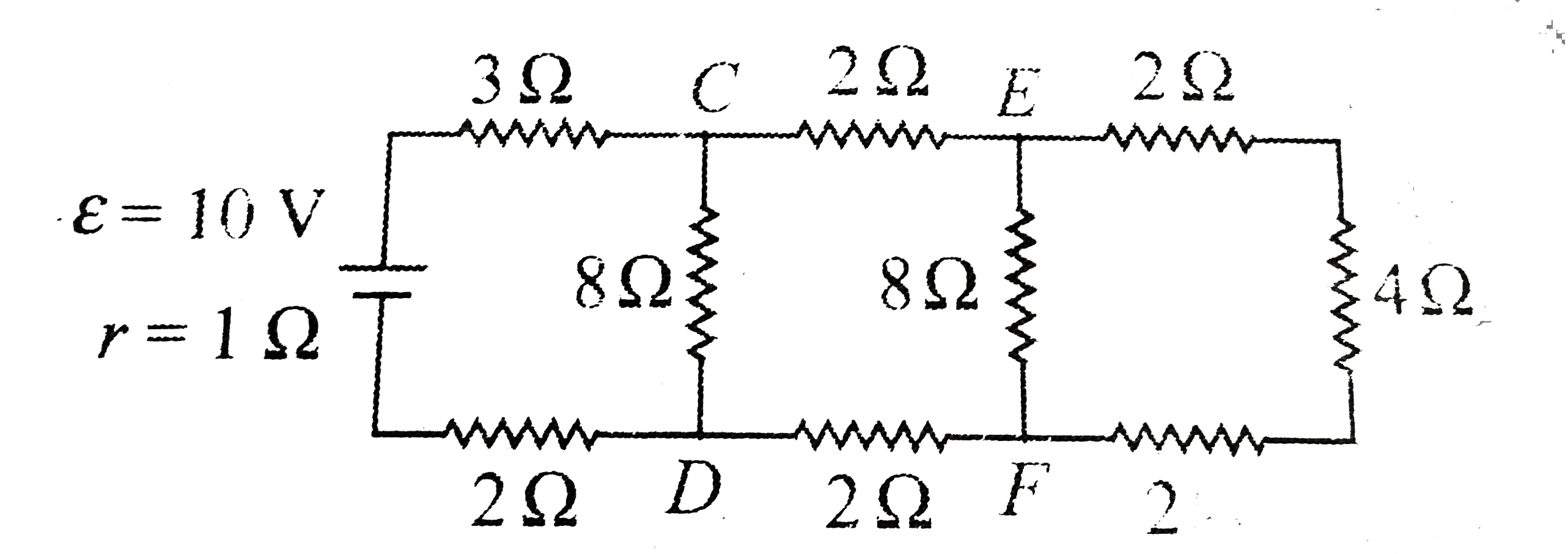
View SolutionIn the circuit shown in fig. some potential difference is applied between A and B. The equivalent resistance between A and B is R.

View SolutionA uniform wire of resistance `R` is shaped into a regular `n-`sided polygon (`n` is even), The equivalent resistance between any two corners can have.
(i) the maximum value `(R )/(4)`
(ii) the minimum value `( R)/(n)`
(iii) the minimum value `R((n -1)/(n^2))`
(iv) the minimum value `(R )/(n)`.
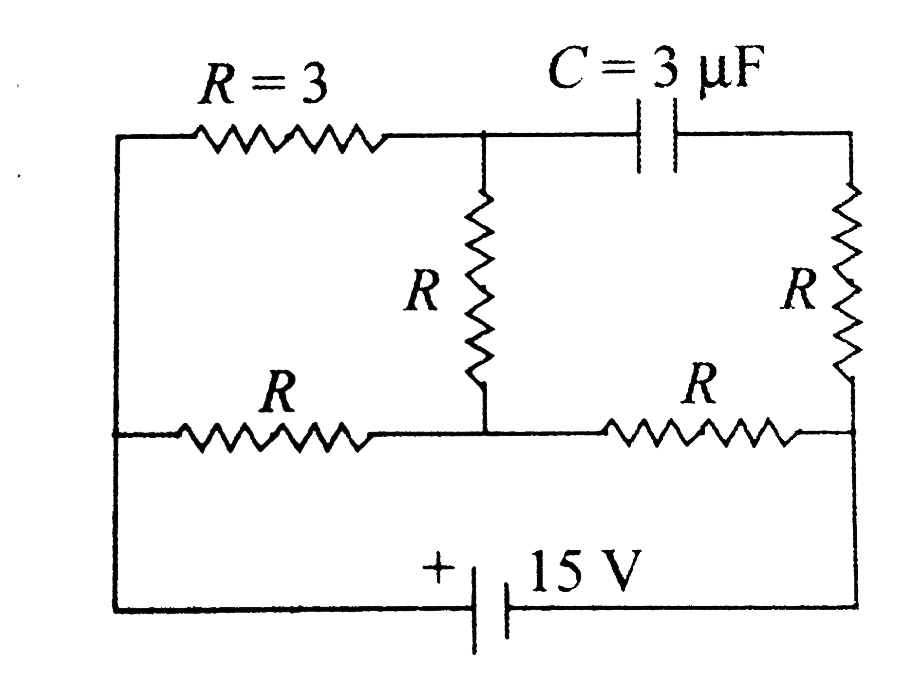
View SolutionIn the circuit shown in fig. the cell is ideal with emf 15V. Each resistance is of `3Omega.` The potential difference across the capacitor in steady state is
View SolutionIn the circuit shown, the cell is ideal with emf = `2V` . The resistance of the coil of the galvanometer `G` is `1 Omega`.

(i) No current flows in `G`
(ii) `0.2A` current flows in `G`
(iii) potential difference across `C_(1) is 1V`
(iv) Potential difference across `C_(2)` is `1.2V`
View Solution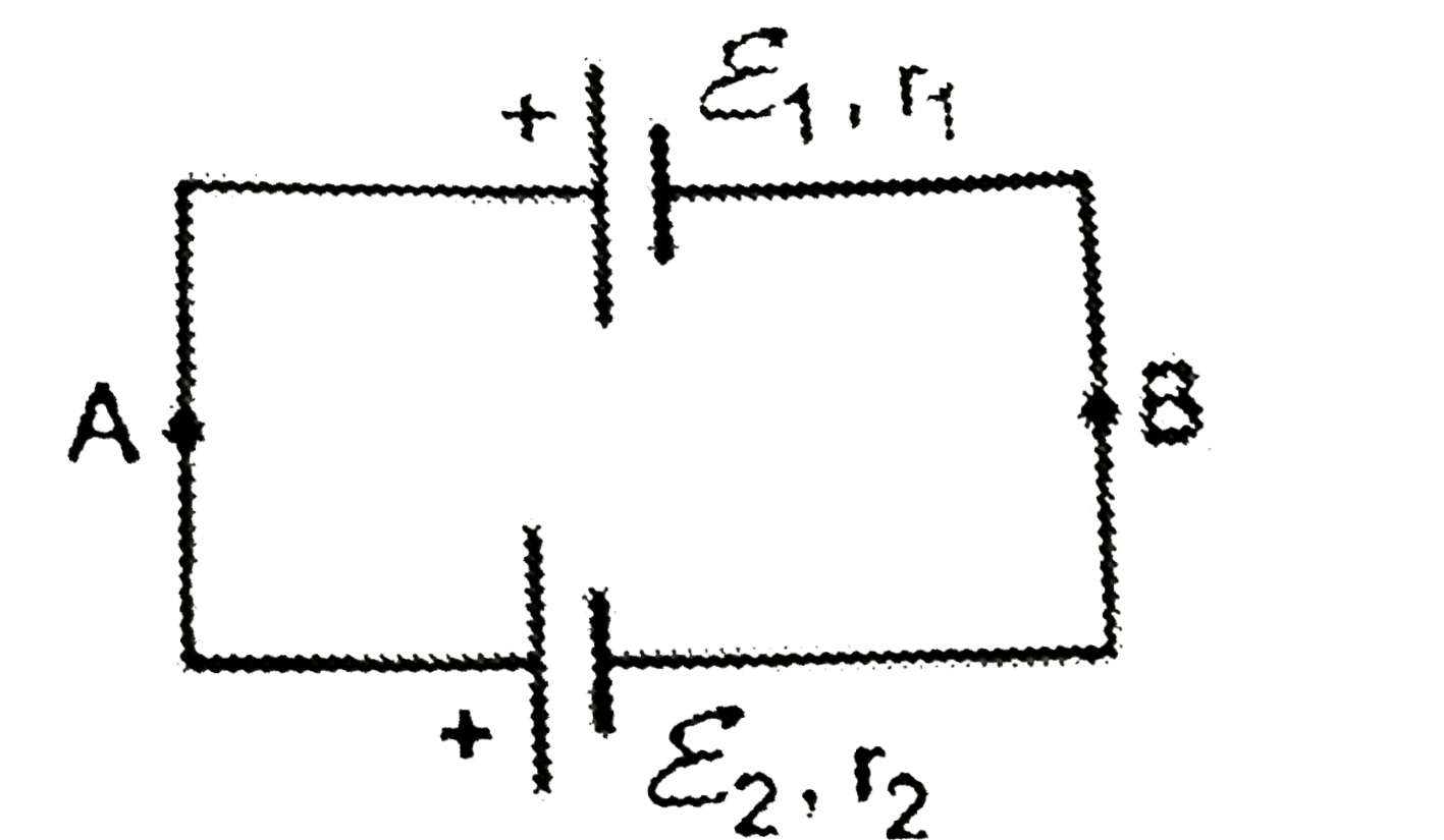
Two cells of unequal emfs, `varepsilon_(1)` and `varepsilon_(2)` and internal resistances `r_(1)` and `r_(2)` are joined as shown. `V_(A)` and `V_(B)` are the potentials at `A` and `B` respectively.
View SolutionAn accumulator battery (storage cell) `B` of emf `epsilon` and internal resistance `r` is being charged from `DC` supply whose terminals are `T_1` and `T_2`
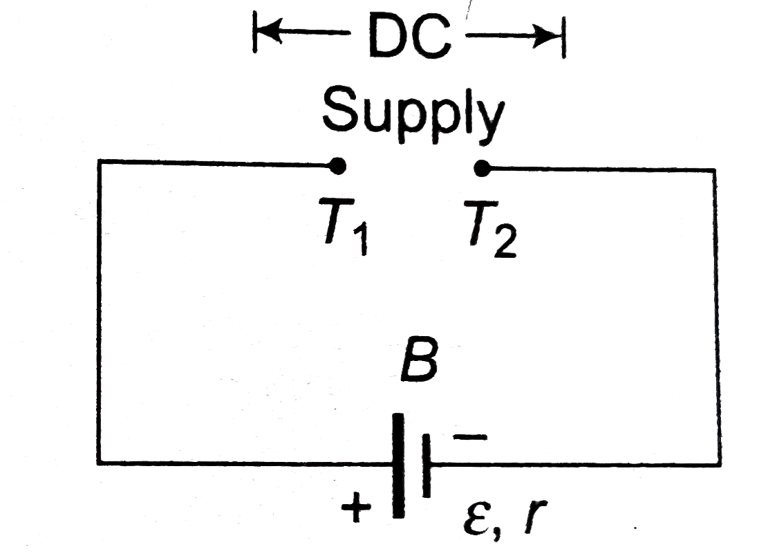 .
.
View SolutionA voltmeter and an ammeter are connected in series to an ideal cell of `emf E`. The voltmeter reading is `V`, and the ammeter readings is `I`. Then
(i) `V lt E` (ii) the voltmeter resistance is `V// I`
(iii) the potential difference across the ammeter is `E - V`
(iv) Voltmeter resistance + ammeter resistance = E//I`
Correct statements are
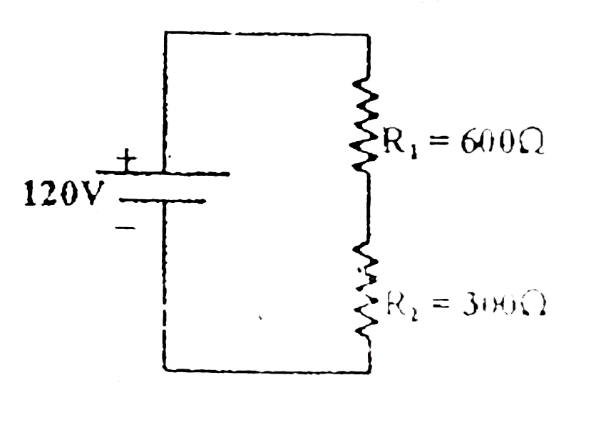
View SolutionA voltmeter of resistance `600 Omega` when connected in turn across resistances `R_(1)` and `R_(2)` gives readings of `V_(1)` and `V_(2)`, respectively. If the battery is ideal, then
View SolutionA voltmeter and an ammeter are joined, in series to an ideal cell, giving reading V and A respectively. If a resistance equal to the resistance of the ammeter is now joined in parallel to the ammeter then :
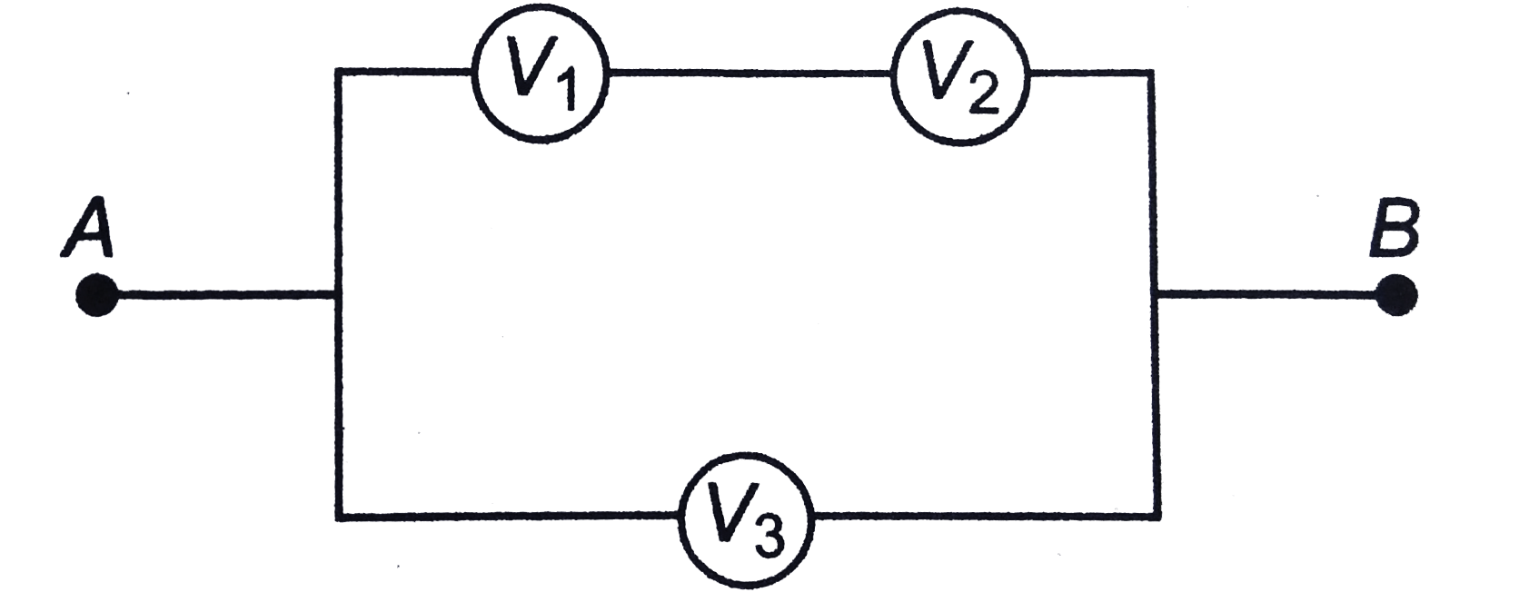
View SolutionThree voltmeters all having different resistance, are joined as shown. When some potential difference is applied acros `A` and `B`, their readings are `V_1,V_2` and `V_3.` Then
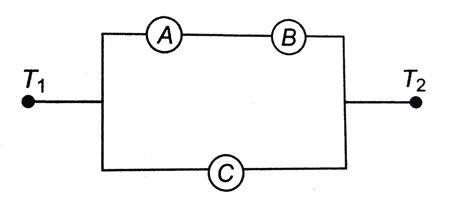
View SolutionThree ammeters `A,B`, and `C` of resistances `R_A,R_b` and `R_C` respectively are joined as shown. When some potential difference is appllied across the terminals `T_1` and `T_2` their readings are `I_A,I_B and I_C` respectively Then,
View SolutionA microameter has a resistance of `100 omega` and a full scale range of ` 50 muA`. It can be used as a voltmeter or as a higher range ammeter provides a resistance is added to it . Pick the correct range and resistance combination(s)
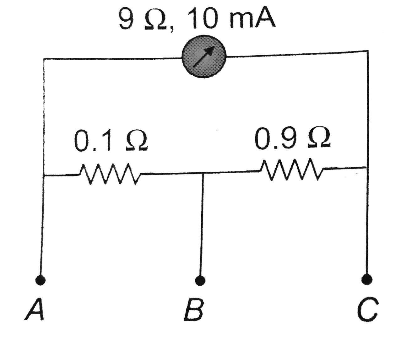
View SolutionA milliammeter of range `10 mA` and resistance `9 Omega` is joined in a circuit as shown. The metre gives full-scale deflection for curretn `I` when `A` and `B` are used as its terminals, i.e., current enters at `A` and leaves at `B` (`C` is left isolated). The value if `I` is
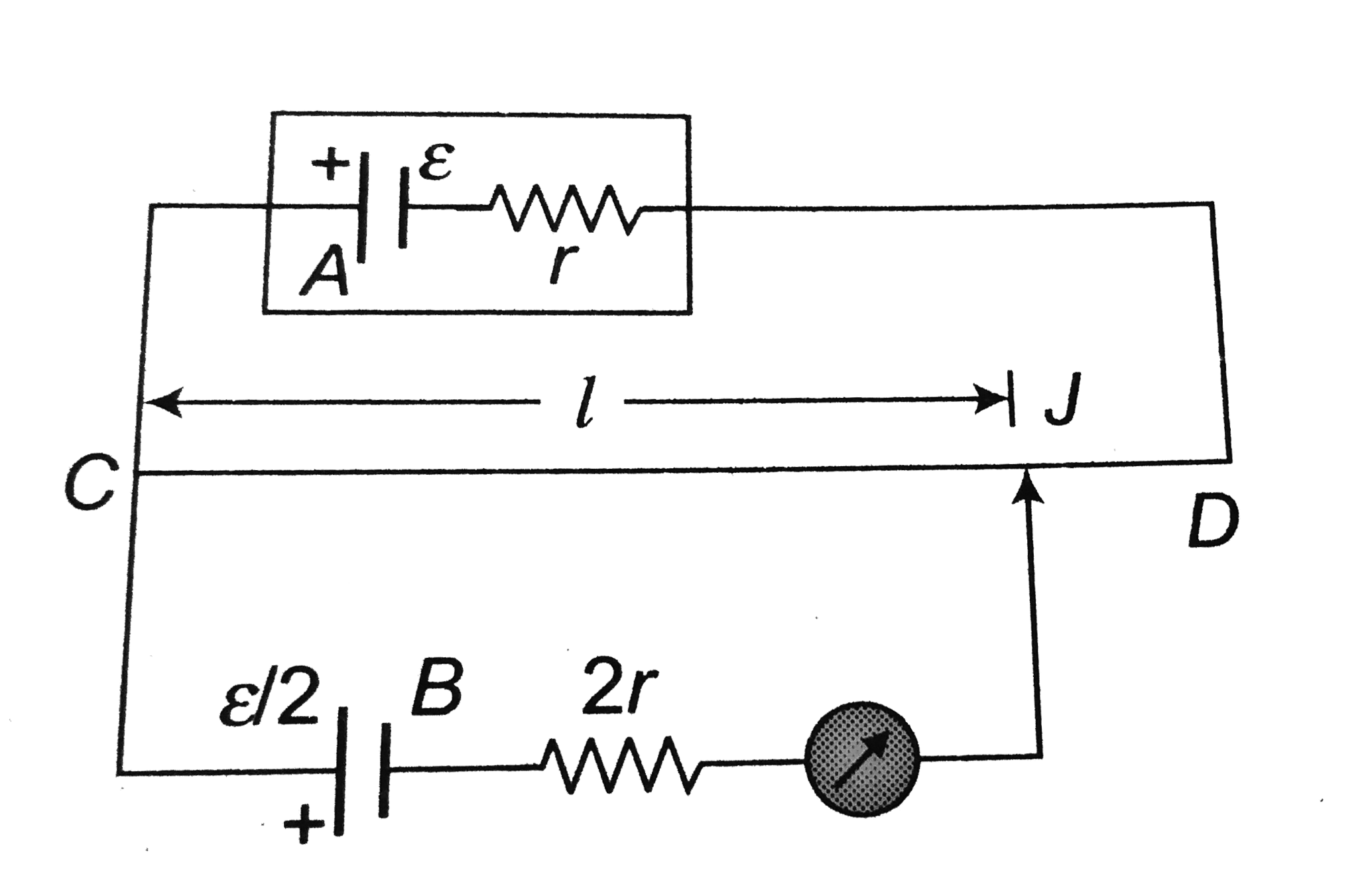
View SolutionIn the petentiometer arrangemeter shown, the driving cell `A` has emf `epsilon` and internal resistance `r`. The emf of the cell `B` is `(epsilon)/(2)` and internal resistance `2r`. The petentiometer wire `CD` is `100 cm` long. If balance is obtained with length `CJ = l`, then
View SolutionA cell drives a current through a circuit. The emf of the cell of equal to the work done in moving unit charge (Choose the incorrect option)
View SolutionA cell of emf `epsilon` and internal resistance `r` drives a current `i` through an extermal resistance `R`
(i) The cell suppllied `epsilon i` power
(ii) Heat is produced in `R` at the rate `epsilon i`
(iii) Heat is produced in `R` at the rate `epsilon I ((R )/(R+r))`
(iv) Heat is produced in the cell at the rate `epsilon i((r ?/(R+r))`
View SolutionCurrent `i` is being driven through a cell of emf `epsilon` and internal resistance3 `r`, as shown
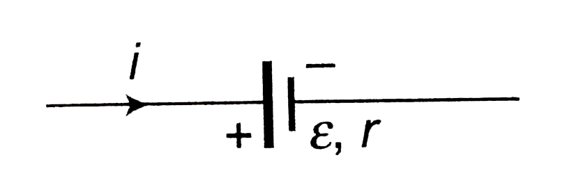
(i) the cell absorbs energy at rate of `epsilon i`
(ii) The cell stores chemical energy at the rate of `(epsilon i - i^(2)r)`
(iii) The potential differnece across the cell is `epsilon+ir`
(iv) some heat is produced in the cell
View SolutionTwo electric bulbs rated `25 W , 220 V and 100 W , 220 V` are connected in series across a `220 V` voltage source . The `25 W and 100 W` bulbs now draw `P_(1) and P_(2)` powers , respectively.
View SolutionTwo heaters designed for the same voltage `V` have different power ratings. When connected individually across as source of voltage` V`, they produce `H` amount of heat each in time `t_1` and `t_2` respectively. When used together acros the same source, they produce H amount of heat in time t
View SolutionTwo identical fuses are rated at `10A`. If they are joined
View SolutionThe charge flowing through a resistance `R` varies with time `t as Q = at - bt^(2)`. The total heat produced in `R` is
View SolutionIn the network shown in fig. , points A, B, and C are at potentials of 70 V, 0, and 10V, respectively.

View SolutionTwo identical capcitors `A` and `B` are charged to the same potential and then made to discharge through resistance `R_(A)` and `R_(B)` respectively with `R_(A) gt R_(B)`
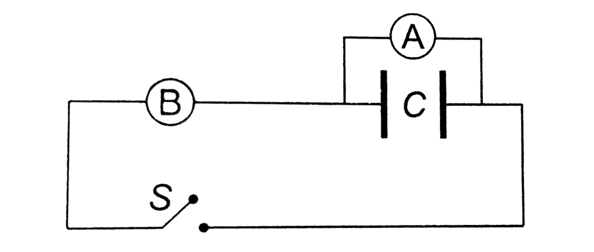
View Solutiona capacitor of capacitance `C` is connected to two voltmeter `A` and `B`. `A` is ideal , having infinite resistance, while `B` has resistance `R`. The capcitor is charged and then switch `S` is closed. The reading of `A` and `B` will be equal
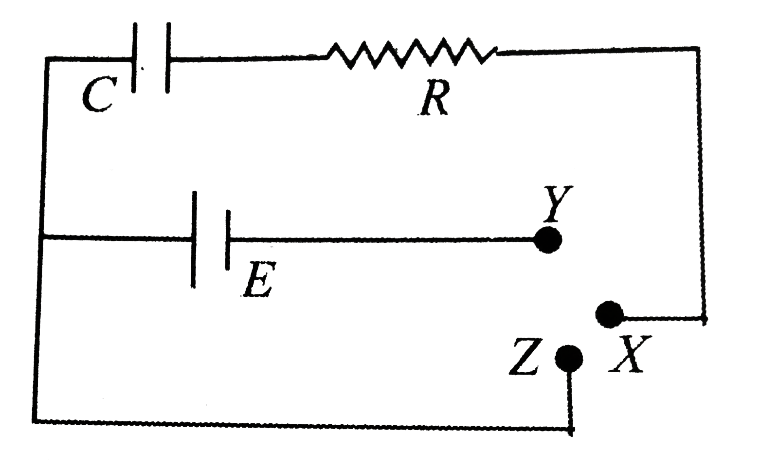
View SolutionThe capacitor C is initially without charge. X is now joined to Y for a long time, during which `H_1` heat is produced in the resistance R. X is now joined to Z for a long time, during which `H_2` heat is produced in R
View SolutionA parallel- plate capacitor, fileld with a dielectric of dielectric consatnt `k`, is charged to a potential `V_(0)`. It is now disconnected from the cell and the slab is removed. If it now discharges, with time constant `tau`, through a resistance then find time after which the potential difference across it will be `V_(0)` ?
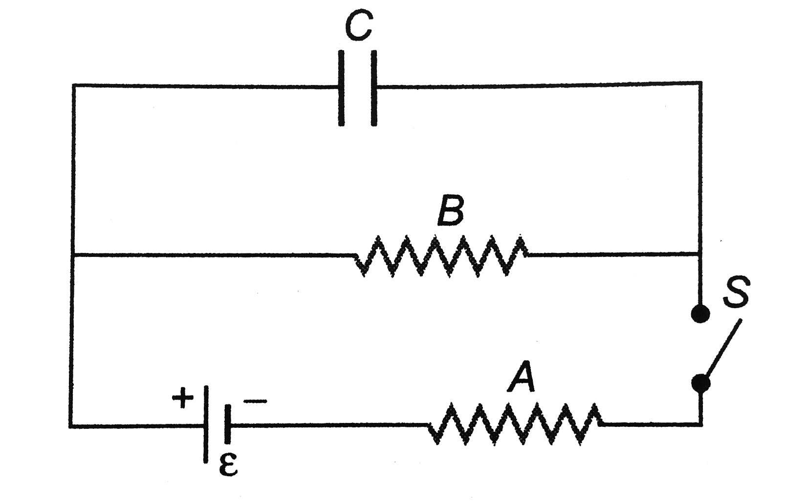
View SolutionIn the circuit shown, `A` and `B` are equal resistances. When `S` is closed, the capcitor Ccharges from the cell of emf epsilon and reaches a steady state.
View SolutionCapacitors `C_(1)=1 muF` and `C_(2)=2muF` are separately charged from the same battery. They are allowed to discharge separately through equal resistors
View Solution
All Questions questions and complete solutions for chapter ELECTRIC CURRENT IN CONDUCTORS of D MUKHERJEE PHYSICS (HINGLISH) of Class 12