Complete Solutions to Exercise -2 : Concept Applicator of chapter ALTERNATING CURRENT of Class 12 book with complete answers and questions
| Class 12 | PHYSICS |
| Chapter | ALTERNATING CURRENT |
| DISHA PUBLICATION | Exercise -2 : Concept Applicator |
| Number Of Questions | 30 |
| Academic Year | 2023-24 |
A series LR circuit is connected to an ac source of frequency `omega` and the inductive reactance is equal to 2R. A capacitance of capacitive reactance equal to R is added in series with L and R. The ratio of the new power factor to the old one is
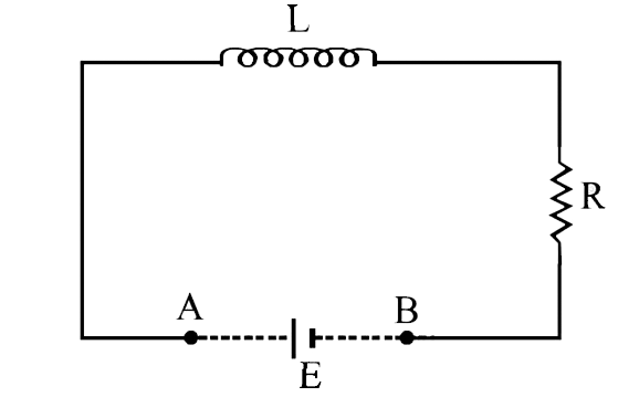
View SolutionAn inductor `(L = 100 mH)`, a resistor `(R = 100 (Omega))` and a battery `(E = 100 V)` are initially connected in series as shown in the figure. After a long time the battery is disconnected after short circuiting the point A and B. The current in the circuit 1 ms after the short circuit is
View SolutionThe primary of a transformer when connected to a dc battery of 10 volt draws a current of 1 mA. The number of turns of the primary and secondary windings are 50 and 100 respectively.The voltage in the secondary and the current drawn by the circuit in the secondary are respectively
View SolutionAn inductive coil has resistance of `100 Omega`. When an ac signal of frequency `1000 Hz` is fed to the coil. The applied voltage leads the current by `45^(@)`. What is the inductance of the coil?
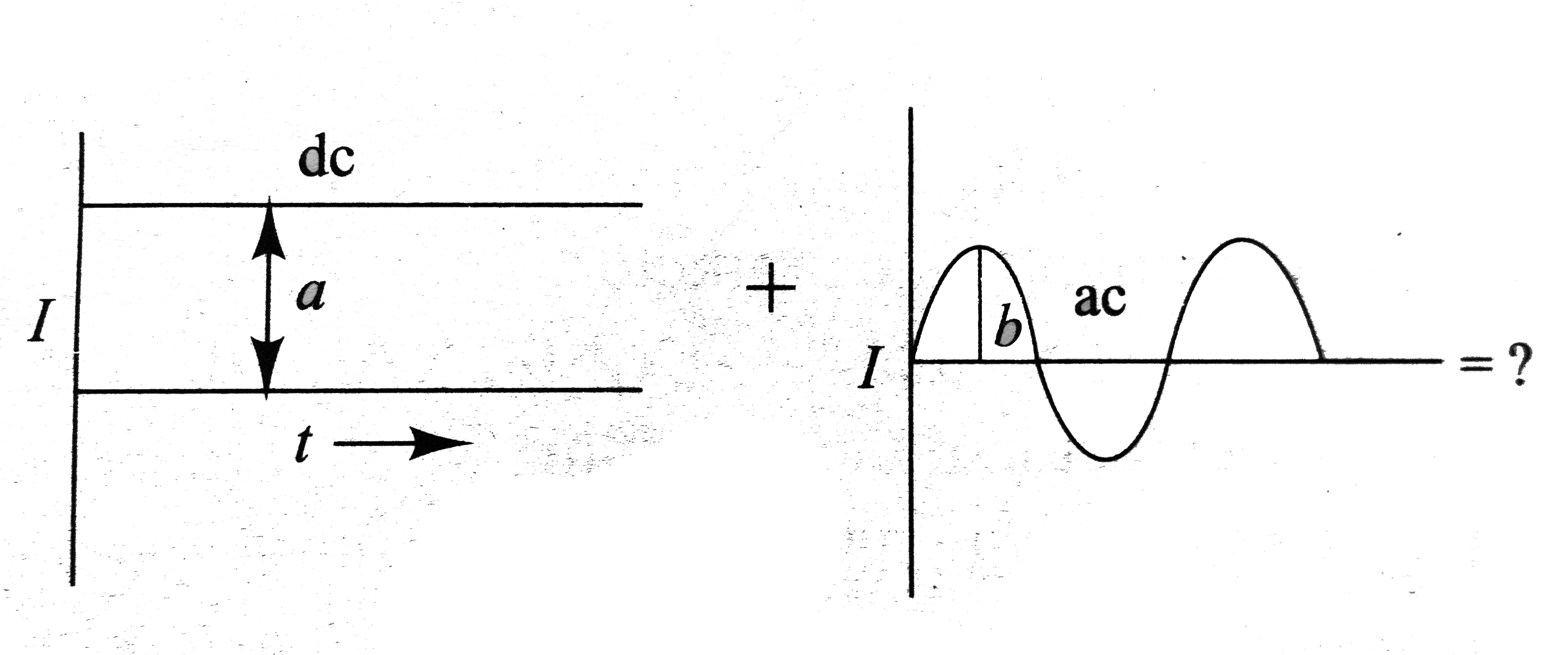
View SolutionIf a direct current of value a ampere is superimposed on an alternative current I=b `sin omega t` flowing through a wire, what is the effective value of the resulting current in the circuit?
View SolutionIn the circuits (A) and (b) switches `S_(1)` and `S_(2)` are closed at t = 0 and are kept closed for a long time.The variation of current in the two circuits for `t ge 0` are roughly shown by figure (figures are schematic and not drawn to scale):

View SolutionCombination fo two identical capacitors, a resistor `R` and a dc voltage source of voltage `6V` is used in an experiment on a `(C-R)` circuit. It is found that for a parallel combination of the capacitor the time in which the voltage of the fully charged combinatiomn reduces to half its original voltage is `10` second. For series combination the time needed for reducing teh voltage of the fully charged series combination by half is-
View SolutionIn an alternating current circuit in which an inductance and capacitance are joined in series, current is found to be maximum when the value of inductance is 0.5 henry and the value of capacitance is 8µF. The angular frequency of applied alternating voltage will be
View SolutionIn a uniform magneitc field of induced B a wire in the form of a semicircle of radius r rotates about the diameter of hte circle with an angular frequency `omega`. The axis of rotation is perpendicular to hte field. If the total resistance of hte circuit is R, the mean power generated per period of rotation is
View SolutionA capacitor of `10 (mu)F` and an inductor of 1 H are joined in series. An ac of 50 Hz is applied to this combination. What is the impedance of the combination?
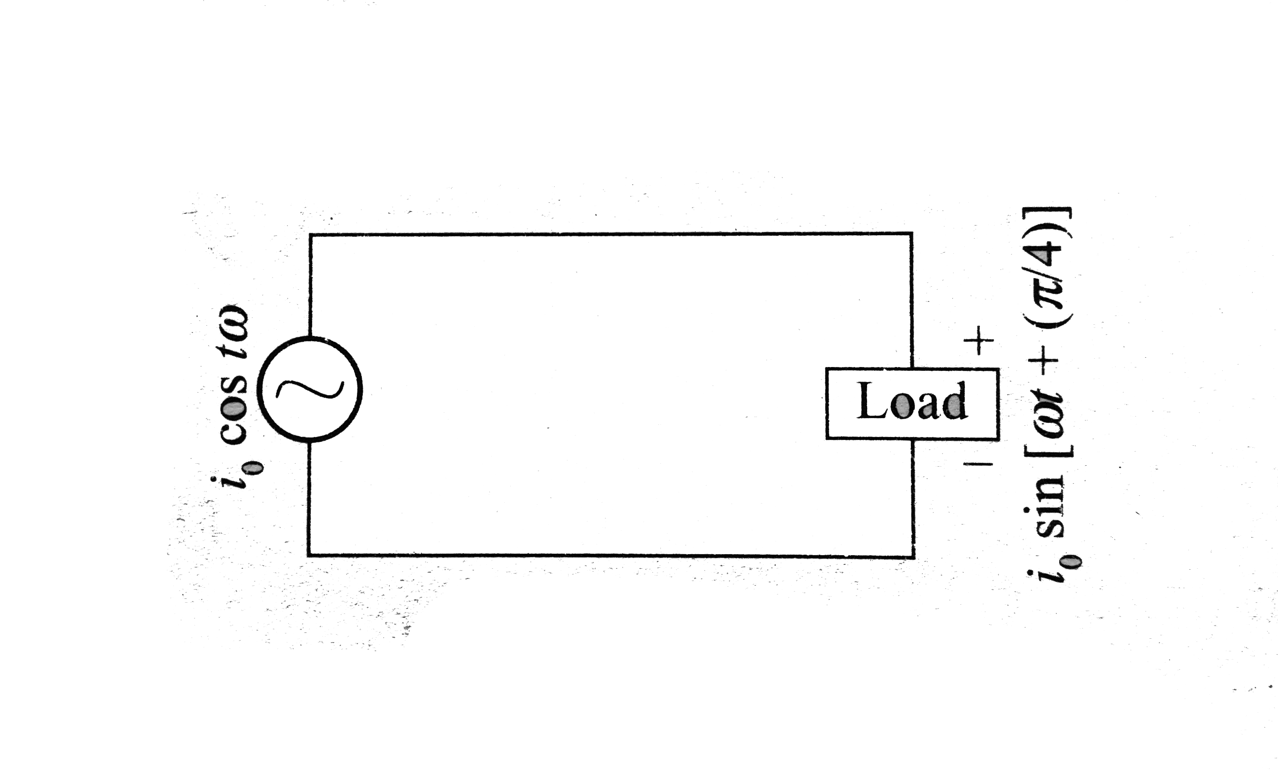
View SolutionA current source sends a current `I=(i_0) cos (omegat)`, When connected across an unknown load, it gives a voltages output of `v=v_(0)sin [omega t+(pi//4)]` across that load. Then the voltage across the current source may bebroaught in phase with the current through it by
View SolutionIn a series LCR circuit `R= 200(Omega)` and the voltage and the frequency of the main supply is 220V and 50 Hz respectively. On taking out the capacitance from the circuit the current lags behind the voltage by `30(@)`. On taking out the inductor from the circuit the current leads the voltage by `30(@)`. The power dissipated in the LCR circuit is
View SolutionAn ideal efficient transformer has a primary power input of 10 kW.The secondary current when the transformer is on load is 25 A. If the primary : secondary turnsratio is 8 : 1, then the potential difference applied to the primary coil is
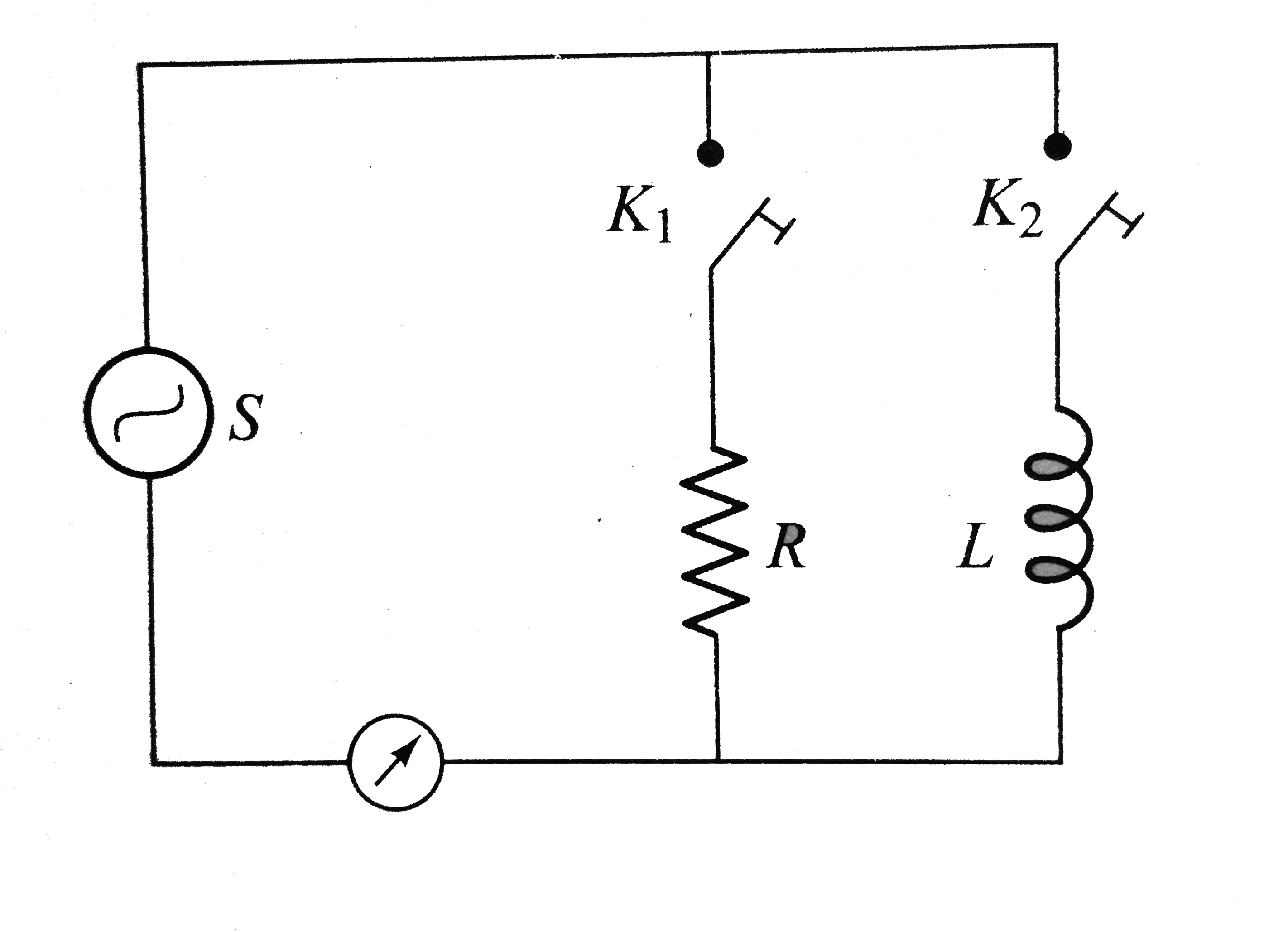
View SolutionIn the circuit shown in fig. R is a pure resistor, L is an inductor of ngligibe resistance (as compared to R), S is a 100 V , 50 Hz ac source of negligible resistnce. With either kiy `(K-1) `alone or `(K_2)` alone closed, the current is `(I_0)`. If the source os changed to 100 V, 100 Hz the current with `(K_1)` alone closed and with `(K_2)` alone closed will be, respectively.
View SolutionAn inductive circuit contains a resistance of 10 ohms and an inductance of 2 henry. If an alternating voltage of 120 V and frequency 60 Hz is applied to this circuit, the current in the circuit would be nearly
View SolutionIn given circuit capacitorinitially uncharged.Now at t = 0 switch S is closed then current given by source at any time t is
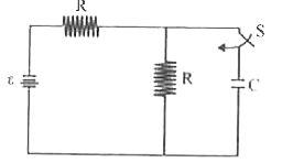
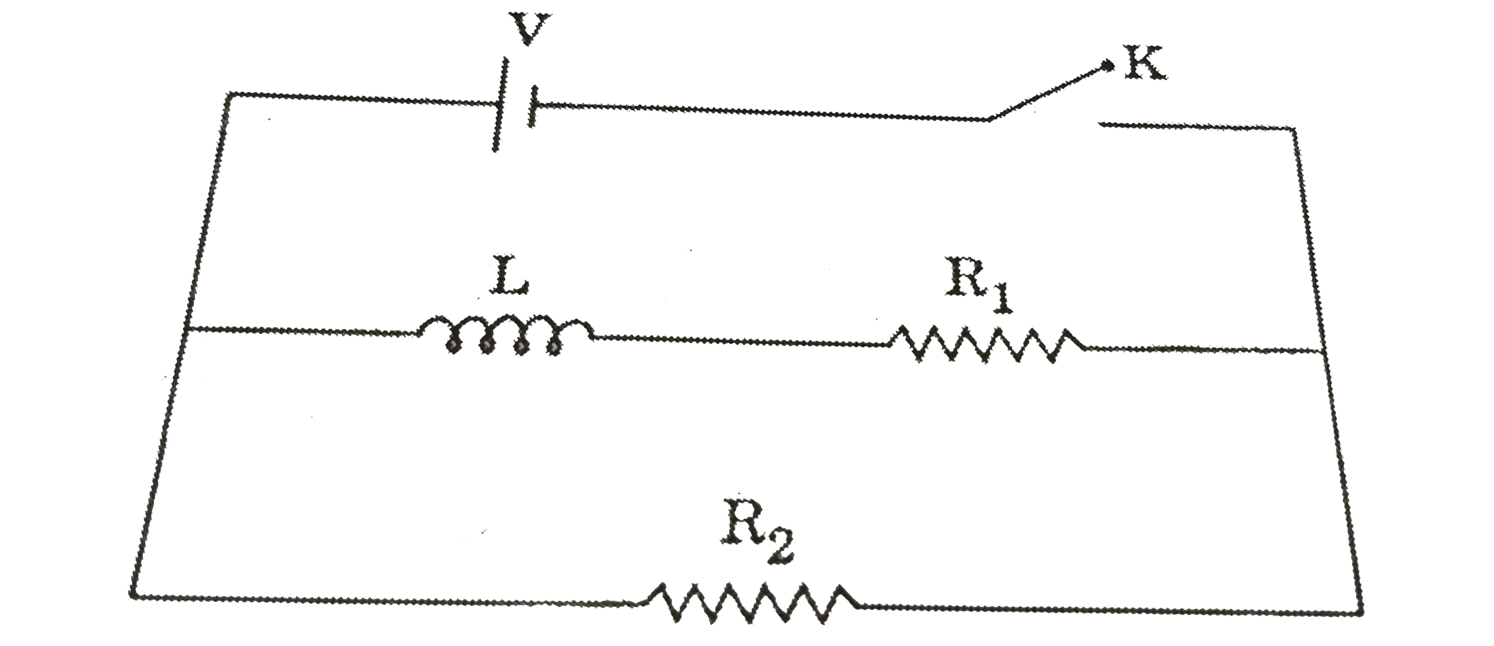
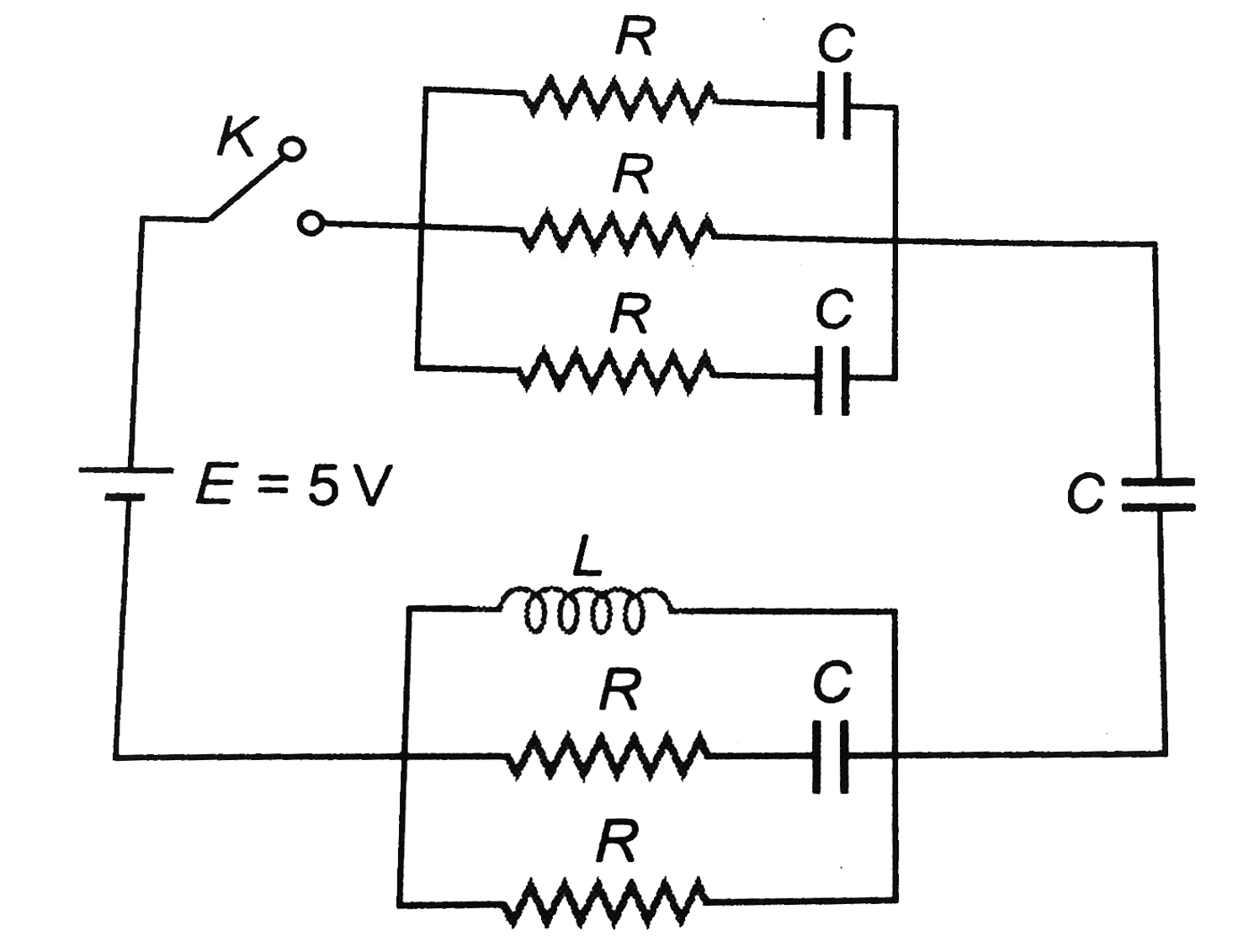
View SolutionIn the circuit shown below, the key K is closed at t = 0. The current through the battery is
View SolutionIn a sereis L-C-R circuit, `C = 10^(-11)` Farad, `L = 10^(-5)` Henry and R = 100 Ohm, when a constant D.C voltage E is applied to the circuit, the capacitor acquires a charge `10^(-9)C`. The D.C source is replaced by a sinusoidal voltage source in which the peak voltage `E_(0)` is equal to the constant D.C volatge E. At resonance the peak value of the charge acquired by the capacitor will be :
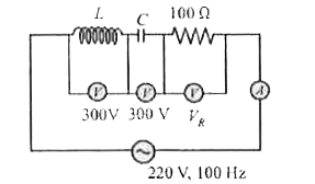
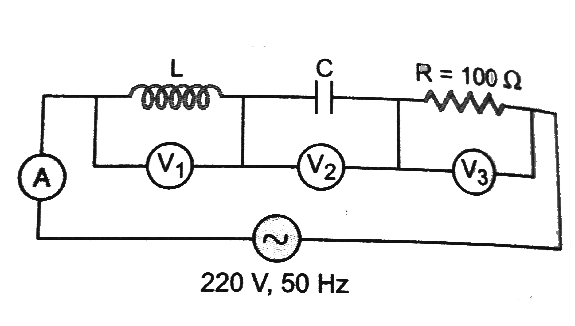
View SolutionIn an LCR circuit shown in the following figure, what will be the readings of the voltmeter across the resistor and ammeter if an a.c. Source of 220 V and 100Hz is connected to it as shown?
View SolutionAn `AC` voltage is applied to a resistance `R` and an inductance `L` in series. If `R` and the inductive reactance are both equal to `3 Omega`, the phase difference between the applied voltage and the current in the circuit is
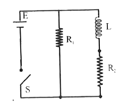
View SolutionAn inductor of inductance L = 400 mH and resistors of resistance `R_(1) = 2 Omega` and `R_(2) = 2Omega` are connected to a battery of emf 12V as shown in the figure.The internal resistance of the battery is negligible.The switch S is closed at t = 0.The potential drop across L as a function of time is
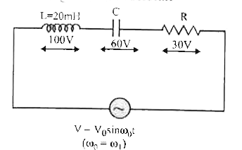
View SolutionConsider the RLC circuit shown below connected to an AC source of constant peak voltage `V_(0)` and variable frequency `omega_(0)`.The value of L is 20 mH.For a certain value `omega_(0) = omega_(1)`, rms voltage across L,C, R are shown in the diagram. At `omega_(0) = omega_(2)`, it is found that rms voltage across resistance is 50 V. Then the value of `omega_(2)` is
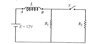
View SolutionThe circuit shown has been operating for a long time. The instant after the switch in the circuit labeled S is opened, what is the voltage across the inductor `V_(L)` and which labeled point (A or B) of the inductor is at a higher potential?Take `R_(1) = 4.0 omega, R_(2) = 8.0 omega and L = 2.5 H`.
View SolutionFind the time constant (in `mu s`) for the given RC circuits in the given order respectively.
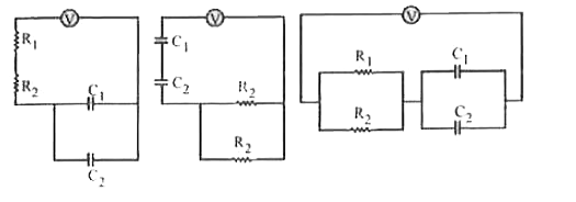
`R_(1) = 1 omega, R_(2) = 2 omega, C_(1) = 4muF, C_(2) = 2mu F`
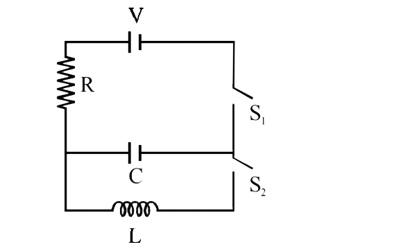
View SolutionIn an LCR circuit as shown below both switches are open initially. Now switch `S_(1)` kept open. (q is charge on the capacitor and `tau = RC` is Capacitive time constant). Which of the following statement is correct?
View SolutionIn an electrical circuit, R, I, C and AC voltage source are all connected in series. When L is removed from the circuit, the phase difference between the voltage and current in the circuit, is `(pi)/(3).` Instead, if C is removed from the circuit, the phase difference is again `(pi)/(3).` The power factor of the circuit is
View SolutionFind the current passing through battery immediately after key `(K)` is closed. It is given that initially all the capacitors are uncharged. (Given that `R=6Omega` and `C=4muF)`
View SolutionThe two capacitors, shown in the circuit, are initially uncharged and the cell is ideal.The switch S is closed at t = 0.
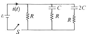
Which of the following functions represents the current i(t), through the cell as a function of time?Here `i_(0), i_(1), i_(2)` are constants.
View SolutionIn the given circuit, Fig., the reading of voltmeter `V_(1)` and `V_(2)` 300 votls each. The reading of the voltemeter `V_(3)` and ammeter `A` are respectively
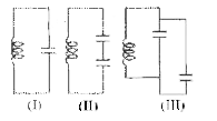
View SolutionFigure shows three oscillating LC circuit with identical inductors and capacitors.If `t_(1),t_(2), t_(3)` are the time taken by the circuits I, II, III for fully discharge, then
View Solution
Exercise -2 : Concept Applicator questions and complete solutions for chapter ALTERNATING CURRENT of DISHA PUBLICATION PHYSICS (HINGLISH) of Class 12