Complete Solutions to All Questions of chapter ELECTROMAGNETISM of Class 12 book with complete answers and questions
| Class 12 | PHYSICS |
| Chapter | ELECTROMAGNETISM |
| LA SENA | All Questions |
| Number Of Questions | 24 |
| Academic Year | 2023-24 |
Currents `l_1 and I_2` flow in the same direction along two parallel conductors, with `l_1 gt l_2` • In which of the three regions `I, I I or I II`, and at what distance from the conductor carryi ng current 11 is the magnetic induction equal to zero?
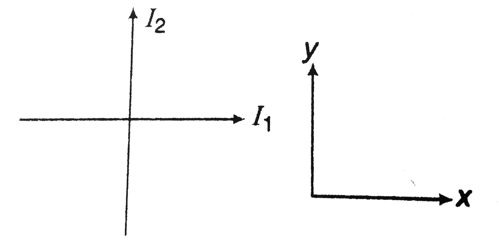
04:17View SolutionTwo long mutually perpendicular conductors carrying currents `I_1` and `I_2` lie in one plane, Find the locus of points at which the magnetic induction is zero.
 02:11View Solution
Equal currents are flowing along three conductors: a ring of radius R (Figure (a)), an infinitely long straight conductor that forms a loop of the same radi us R (Figure (b)), and an infinitely long straight conductor that also forms a loop of radius R but is broken at the point where the loop touches the conductor (Figure (c)). Find the relationships that link the magnetic induction vectors at the center of each circle.
04:12View SolutionThree conductors carrying currents are perpcndicular to the plane of the drawing. They intersect the plane at three points that lie on a single straight line, wi th the distances from the middle conductor to the other two being equal. The currents in the outer conductors flow away from the reader, while the current in the middle conductor flows toward the reader. How is the magnetic Held vector directed at the point on the straight line that is perpendicular to the straight line passing through the three conductors in the plane of the drawing and is separated from the middle conductor by a distance equal to the distances between that conductor and the outer conductors? All three currents are equal in magnitude .
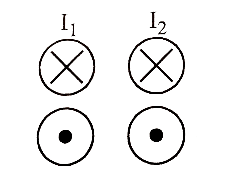
06:37View SolutionA system of long four parallel conductors whose sections with the plane of the drawing lie at the vertices of a square there flow four equal currents The directions of these currents are as follows those marked ox point away from the reader, while those marked with a dot point towards the reader How is the vector of magnetic induction directed at the centre of the square?
 .03:11View Solution
Two infinitely long parallel conductors carrying currents are directed at right angles to the plane of the drawing. The maximum of magnetic induction is at a point M that lies in the middle between the conductors. The direction of the magnetic induction vector B at this point coincides with the positive direction on the x axis. Determine the direction of the currents flowing in the conductors and the relationship that exists between these currents.
05:43View SolutionTwo infinitely long parallel cond uctors carrying currents are directed at right angles to the plane of the drawing. The magnetic induction at a point M that lies in the middle between the conductors is zero. To the right of this point, the magnetic induction vector points upward, at right angles to the x axis. Find the direction of the currents flowing in the conductors, the direction of the magnetic induction vector to the left of point M, the relationship between the currents, and the point on the x axis at which the magnetic induction is maximal. The distance between the conductors is a.
09:31View SolutionA current flows clockwise in a flat square loop. In the plane of the loop there lies an infInitely long straight conductor carrying a current whose direction is designated by the arrow in the figure. How will the loop move in the magnetic field created by the current flowing in the straight conductor and how wi ll the shape of the loop change as a result of the action of this field?
05:30View SolutionAt a small distance from a solenoid carrying a current thero is placed a contour with a current in such a manner that the solenoid's axis lies in the plane of the contour. The directions of the currents in solenoid and contour are shown by arrows. How docs the contour move? I-Iow will it IJlOVe if the current in it flows in the direction opposite to the one shown in the figure?
04:23View SolutionBetween two fixed contours, `1 and 3,` carrying currents that flow in the same direction there is suspended another conl.our, 2, that also carries a current. Contour 2 is oriented i 1 such a manner that the forces caused by the currents in contours `1 and 3` are opposite in direction, equal in magnitude, and lie along a single straight line, thus, contour 2 is in equilibrium. Is this state of equilibrium stable or unstable? Consider the case where the current in contour 2 has the same direction as the currents in `1 and 3` and the case \vhere the direct ions are opposite.
06:37View SolutionTwo contours whose planes are parallel to each other and are separated by a certain distance carry currents that flow in the same direction. One contour is left fixed while the other is positioned in a different manner with respect to the first: in one case its plane is turned by `90^@` , in the other by `180^@`, while in the third case it is just moved parallel to itself over a certain distance. In which of these three eases one will have to perform the greatest work and in which, the smallest?
06:21View SolutionA charged particle of m and charge Q has acquired a certain velocity by passing through a potential di Iierence `U_o`. With this velocity it flies into the field of a parallel-plate capacitor, with the distance between the plates being L, the potential di fference bei ng U. The velocity of the particle is directed parallel to the plates. Where should the magnetic field that makes the particle move along a straight line in the capacitor be directed and what should its value be (the induction B) ?
04:52View SolutionTwo contours are positioned in such a manner that their planes are parallel to each other. Contour 1 carries a current whose direction is designated by an arrow. The contours move in relation to one another, but their planes remain parallel in the process. What is the direction of the current induced in contour 2 when the contours are moved toward each other or away from each other?
03:23View SolutionA spiral made Irorn elastic wire is connected to a `DC` source The spiral is stretched. Will the current flowing in tho spiral become greater or smaller in the stretching process. than tho initial current or will it remain unchanged?
03:28View SolutionA solenoid carrying a current supplied by a `DC` source with a constant emf contains an iron core inside it. How will the current change when the core is pulled out of the solenoid: will it increase, decrease, or remain the same?
02:16View SolutionTwo identical inductances carry currents that yarr with time according to linear laws, In which of the two inductances is the self-induction emf greater? Will the values or signs of the self-induction emf's change if the currents begin to increase in the opposite direction after they pass through zero (with the linear laws retained in the process)?
03:25View SolutionA current that varies with time according to a law depicted graphically in the figure passes through an induction coil. In which of the moments denoted in the figure will the self-induction emf be maximal (the inductance of the coil rernains unchanged in the process)?
03:15View SolutionVarious circuits are used to observe the phenomenon of self-induction. Among these are the circuits shownig Figures (a) and (h). III Figure (a), key K is initially opened and the current Ilows through the induction coil L and resistor R connected iu series. In Figure (h), key K is initially closed and the current branches on to `R and L.` In both circuits the resistance of the coil L is much lower than R. Can an induction emf be generated in either' one of these circuits that is higher than the emf of the DC source?
07:07View SolutionWhen a certain circuit consisting of a constanteuif, an inductance, and a resistance is closed, the current in it increases with time according to curve 1 (see the figure accompanying the problem). After one parumoter (G, L, or R) is changed, the increase in current follows curve 2 when the circuit is closed a second time. Which parameter was changed and in what direction?
03:15View SolutionA current is flowing in a circular contour 1 whoso radius is R. A. second contour, 2, whose radius is much srnaller than that of the first, is moving with a consl ant velocity v along the r axis in such a manner that the planes of the contours remain parallel to each other in the course of the motion. At what distance from contour 1 will the emf induced in contour 2 be maximal?
06:30View SolutionA certain circuit consists of a DC source with emfan induction coil `L1`, and a key `K1`. No resistance is present in the circuit. Another coil, `L2`, which is connected electrically to a resistor R through a key `K2`, is fastened to `L1`. At some moment in time key `K1` is closed. After a certain tirne interval `K2` is closed. flow do the current in the primary circuit (the one containing), the induction emf in the secondary circuit (the one with `L2 and R`), and the current in the secondary circuit vary with time ?
05:17View SolutionAn infinitely long straight conductor and a flat rectangular contour with sides a and b and with N turns lie in a single plane. The distance between the straight conductor and the side of the contour closest to the straight conductor is c. Determine the following quantities: (1) the mutual inductance of the conductor and the contour, (2) the quantity of electricity induced in the contour if the contour is rotated through `90^@` about the AB axis provided that a current I is flowing in the contour and the resistance of the contour is R, (3) the work that must be done to rotate the contour through 1800 about the AB axis provided that there is current I both in the long conductor and in the contour and that the sense of the current in the contour is clockwise (in the plane of the drawing).
08:40View SolutionA flat coil with a cross-sectional area S and with N turns is placed in a magnetic field. The leads of the coil are connected to an oscillograph. When the coil is moved out of the lield, an induction emf is generated in it, and the oscillogram of this emf is shown in the figure. How do the maximal value of the emf, `in_(Im)` and the area under the curve depend on the rate with which the coil is moved out of the field?
02:50View SolutionThe current flowing in a cert.aiu inductance coil varies in time according to the curve shown schematically in the figure. Draw the curve representing the induced emf as a function of time (also schematically).
05:48View Solution
All Questions questions and complete solutions for chapter ELECTROMAGNETISM of IE IRODOV PHYSICS (HINGLISH) of Class 12
