Complete Solutions to MCQ of chapter CURRENT ELECTRICITY of Class 12 book with complete answers and questions
| Class 12 | PHYSICS |
| Chapter | CURRENT ELECTRICITY |
| MARVEL | MCQ |
| Number Of Questions | 100 |
| Academic Year | 2023-24 |
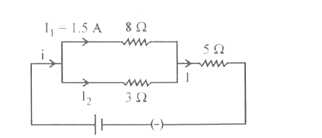
In the given circuit, the current in the `8 Omega` resistance is 1.5 A. What is the total current (I) flowing in the circuit ?
View SolutionThe value of the current I in the given circuit is
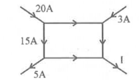
View SolutionWhat is the value of the current I in the following part of an electrical network ?
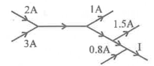
View SolutionIn an open circuit and in a short circuit we have
View SolutionThe Kirchhoff's first law `(sum i=0)` and second law `(sum I R = sum E)` are respectively based upon the conservations of
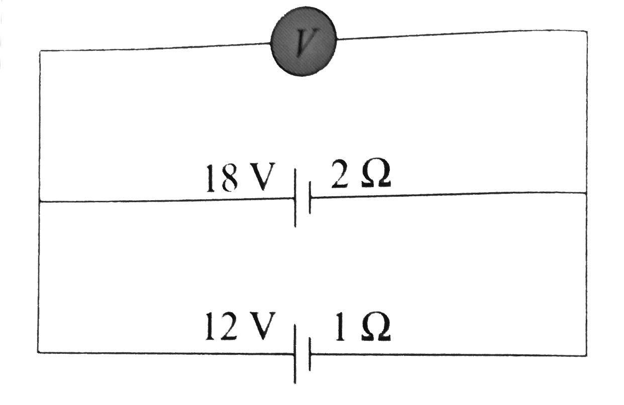
View SolutionTwo batteries, one of emf 18 volts and internal resistance `2 Omega` and the other fo emf 12 volts and internal resistance `1 Omega`, are connected as shown. The voltmeter `V` will record a reading of
View SolutionWhat is the value of the resistance `R_(1)` in the following circuit ?
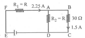
View SolutionWhat is the magnitude and direction of the current in the following circuit ?
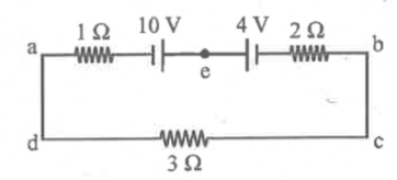
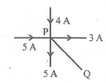
View SolutionFive current carrying conductor meet at a point P. What is the magnitude and direction of the current in the fifth conductor ?
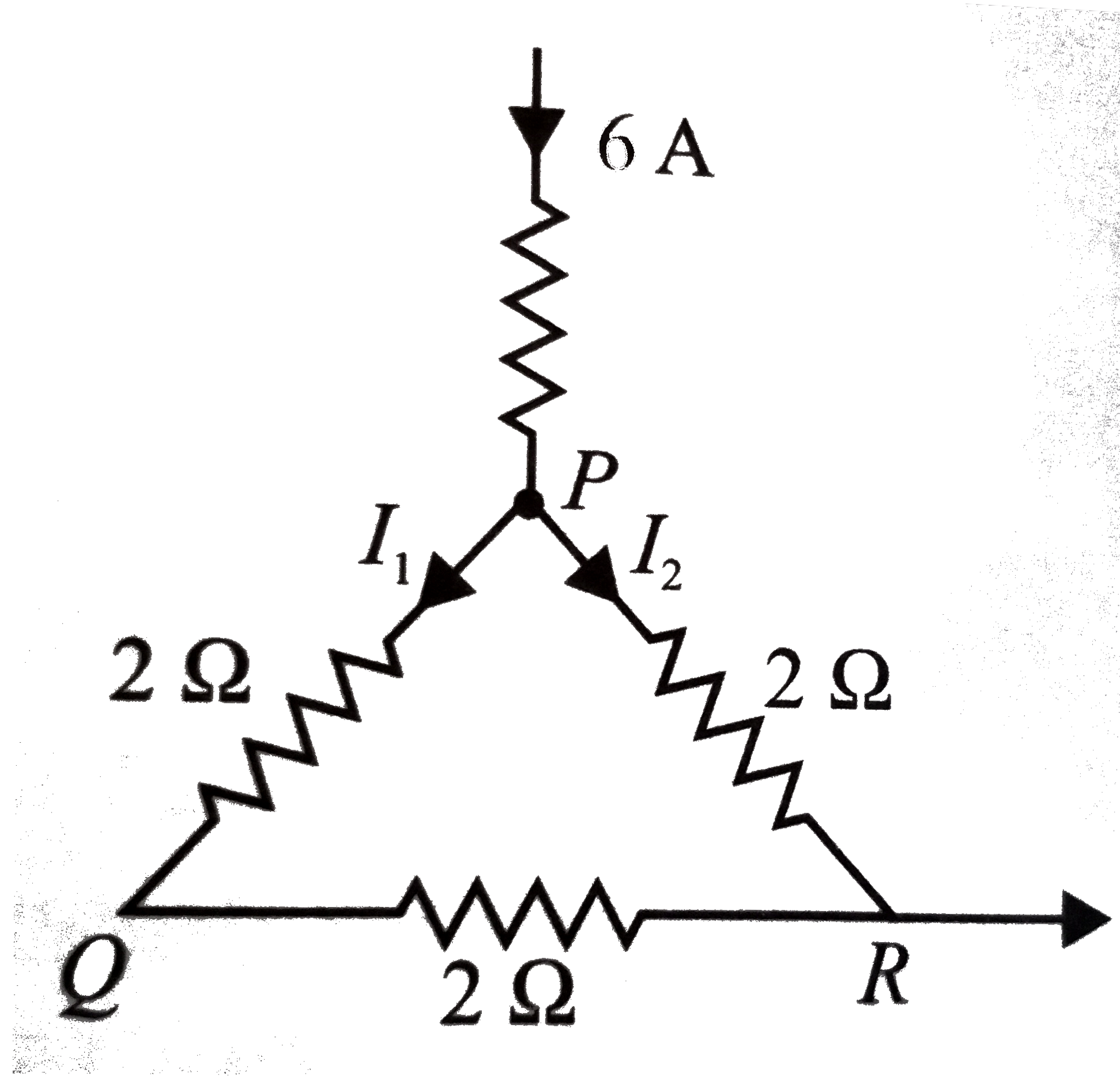
View SolutionA current of 6 A enters one corner P of an equilateral triangle PQR having 3 wires of resistances 2 Q each and leaves by the corner R. Then the currents `I_(1) and I_(2)` are
View SolutionWhat is the current in the given circuit ?
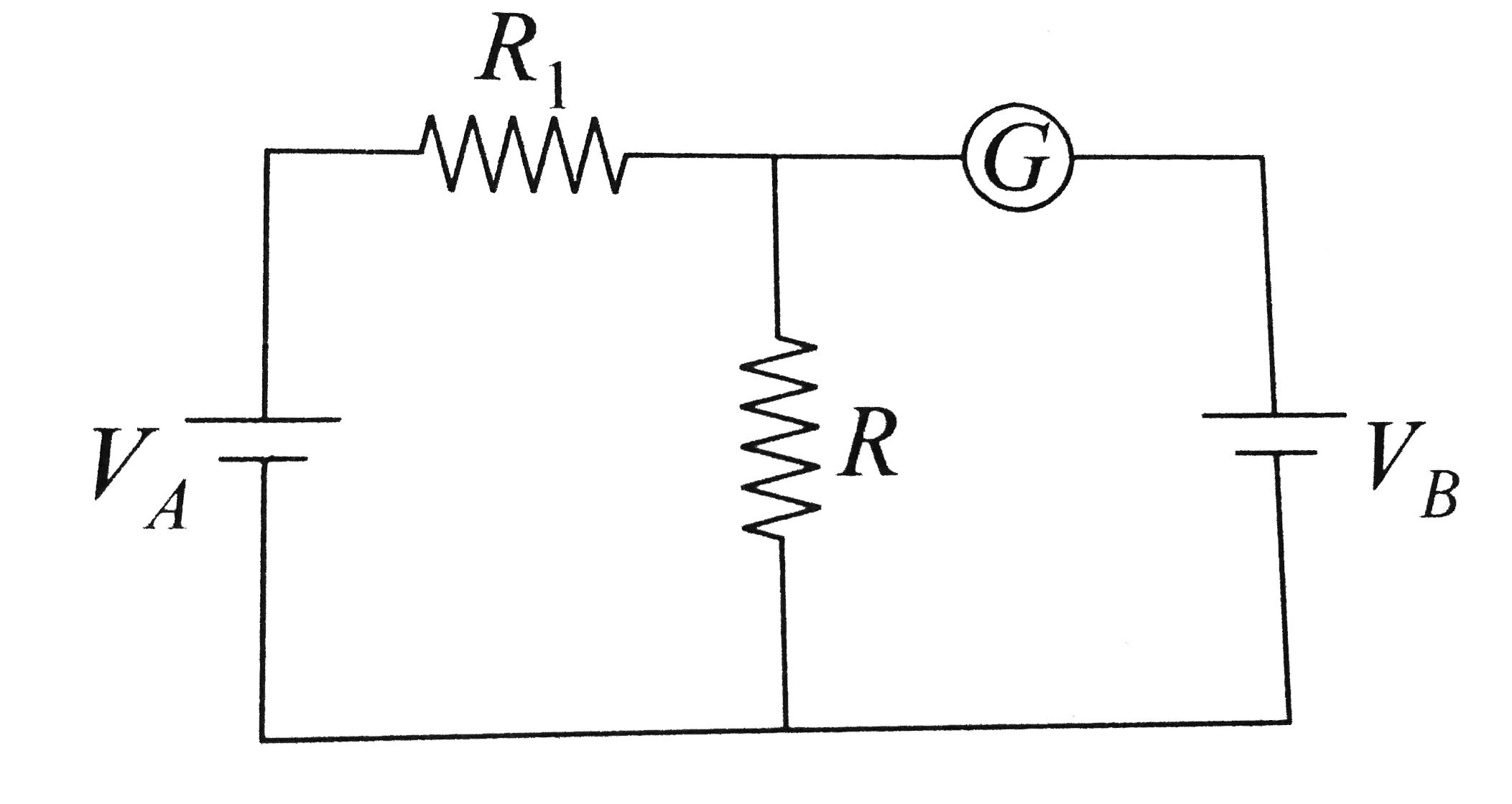
View SolutionIn the circuit shown the cells `A` and `B` have negligible resistance. For `V_(A) = 12 V, R_(1) = 500 Omega` and `R = 100 Omega`, the galvanometer `(G)` shows no deflection. The value of `V_(B)` is
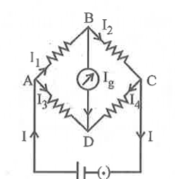
View SolutionA bridge circuit is shown in the diagram. A student wrote the following expressions for currents at the points A, B, C and D by using Kirchhoff's first law. Point out the wrong equation.
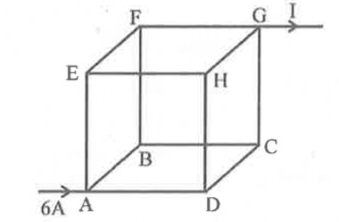
View SolutionTwelve identical wires each of resistance R are joined to form a cube as shown in the figure. A current of 6 ampere enters the cube at A and leaves at G. The current I in the branch FG is

View Solution12 identical wires, each of resistance R are joined to form a cube as shown in the figure. A current of 6 Amperes enters the cube at A. If the wire HG is removed, then the current I leaving the network at G is
View SolutionA 220 volt, 1000 watt bulb is connected across a 110 volt mains supply. What is the power consumed in the circuit ?
View SolutionWhat is the potential difference across the `3 Omega` resistor ?

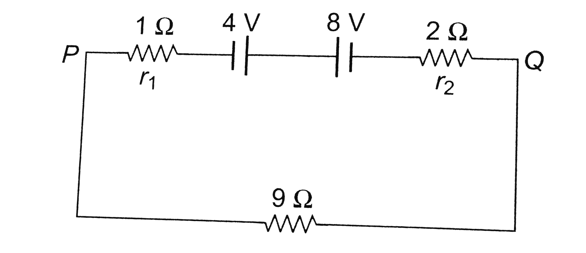
View SolutionTwo batteries of e.m.f. `4V` and `8V` with internal resistances `1 Omega` and `2 Omega` are connected in a circuit with a resistance of `9 Omega` as shown in figure. The current and potential difference between the points `P` and `Q`
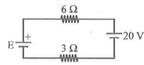
View SolutionWhat are the values of E in the following circuit, if a current of 2 A flows in the clockwise as well as in anticlockwise direction ?
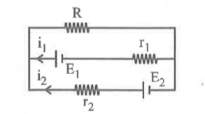
View SolutionWhich one of the following equations is the correct equation for the electrical circuit shown in the figure ?
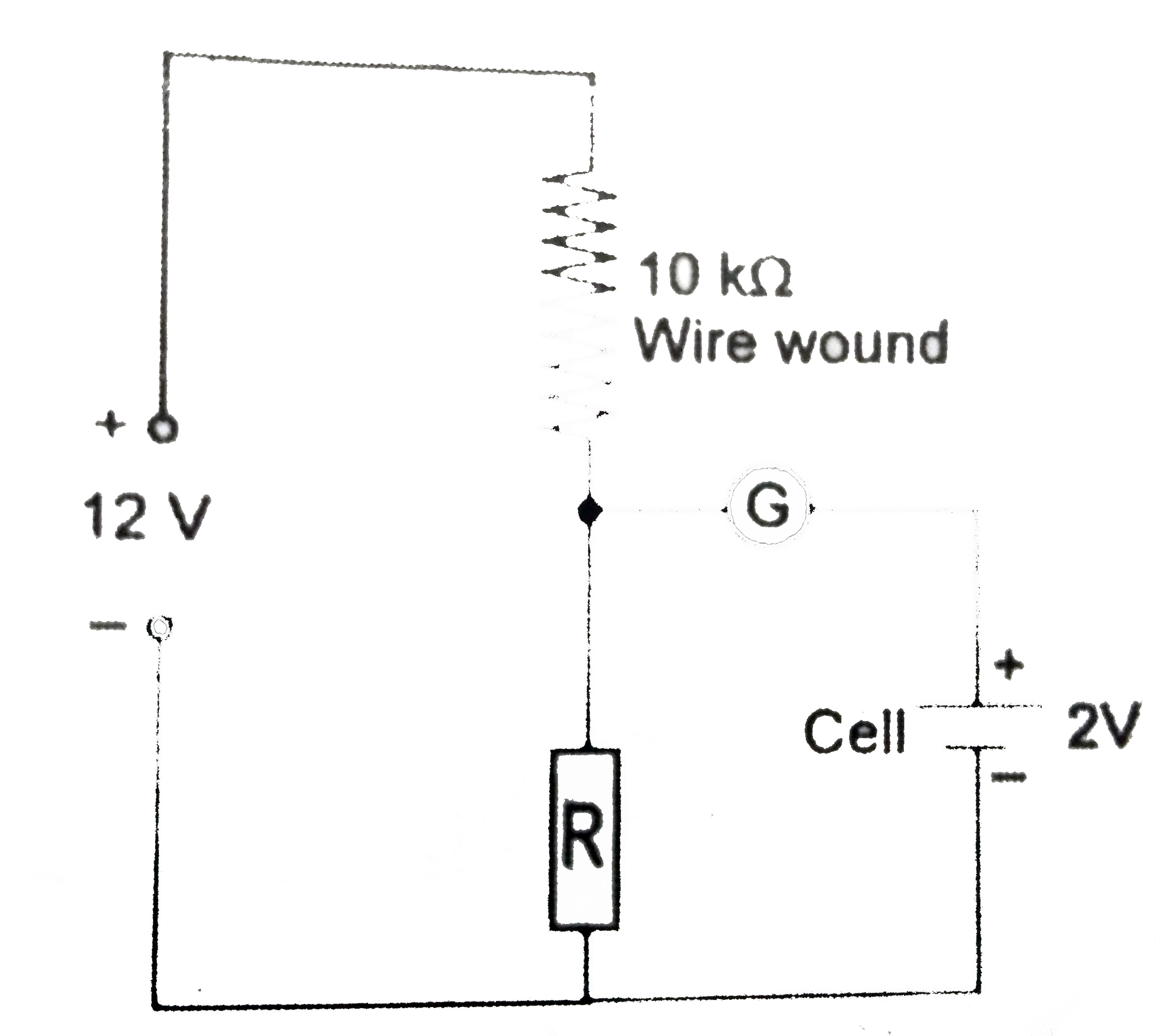
View SolutionIf the galvanometer in the circuit of figure reads zero, calculate the value of the resistor R (ion `Komega`) assuming that the 12 V source has negligble internal resistance.
View SolutionConsider the circuit shown in the figure. What is the value of the current `I_(3)` ?
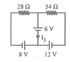
View SolutionWhat is the value of the current `I_(1)` in the given circuit ?
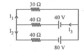
View SolutionIn the circuit given here, the points A,B and C are 70 V, zero, 10 V respectively . Then,
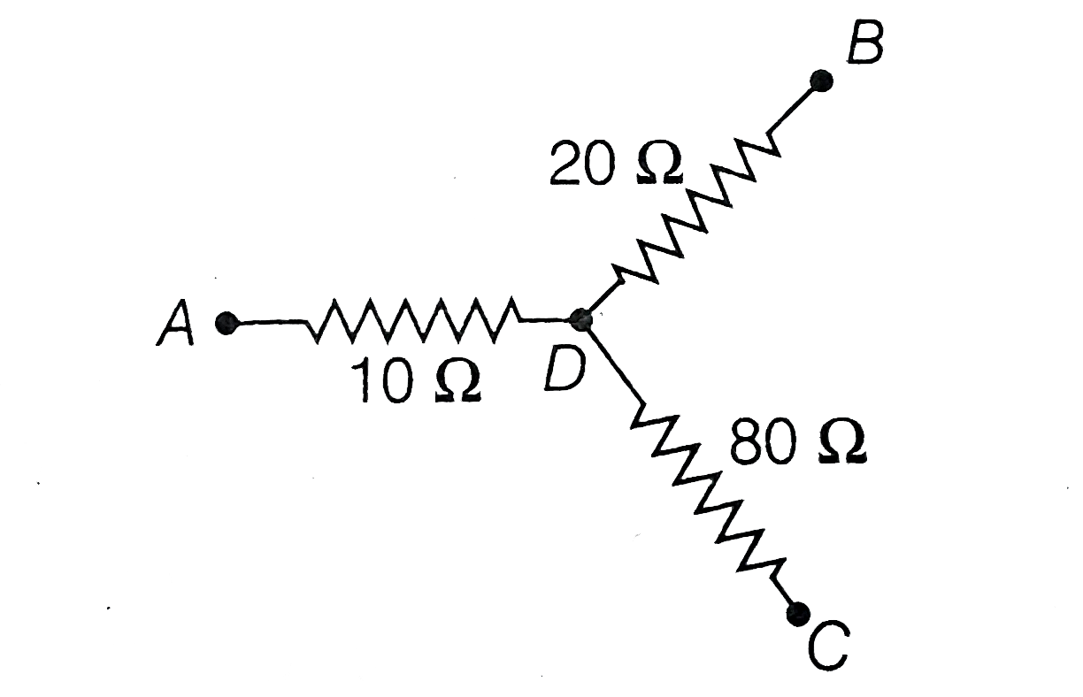
View SolutionIn the circuit shown in the figure, if potentail at point `A` is taken to be zero, the potential at point `B` is
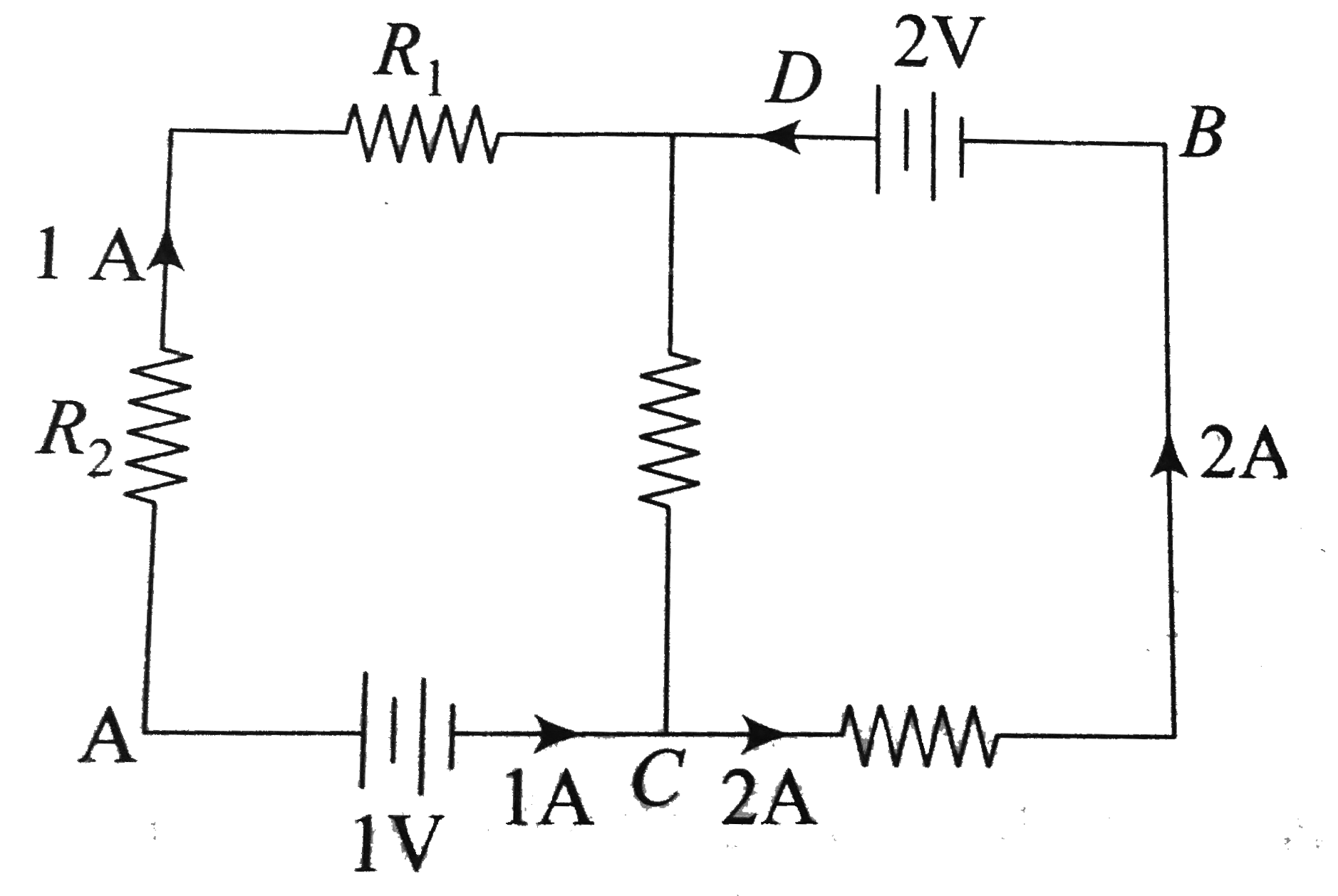
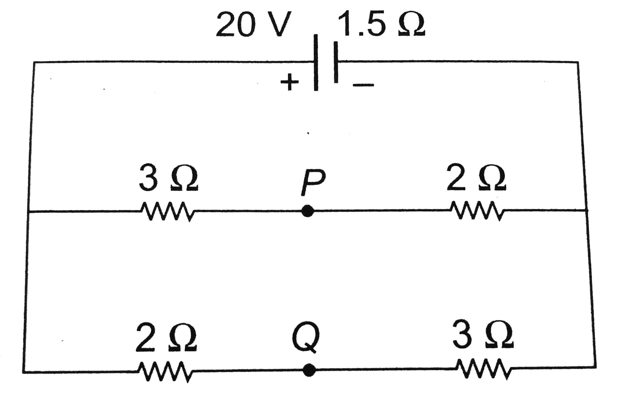
View SolutionIf in the circuit shown below, the internal resistance of the battery is `1.5 Omega` and `V_(P)` and `V_(Q)` are the potential at `P` and `Q` respectively, what is the potential difference between the point `P` and `Q`?
View SolutionA 5V battery with internal resistance `2Omega` and a 2V battery with internal resistance`1Omega` are connected to a `10Omega` resistor as shown in the figure.
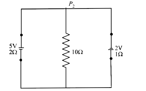
The current in the `10Omega` resistor is
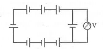
View SolutionIn the following circuit, each cell has an e.m.f. of 5 V and an internal resistance of `0.2 Omega`. What is the reading of the ideal voltmeter V in volts ?
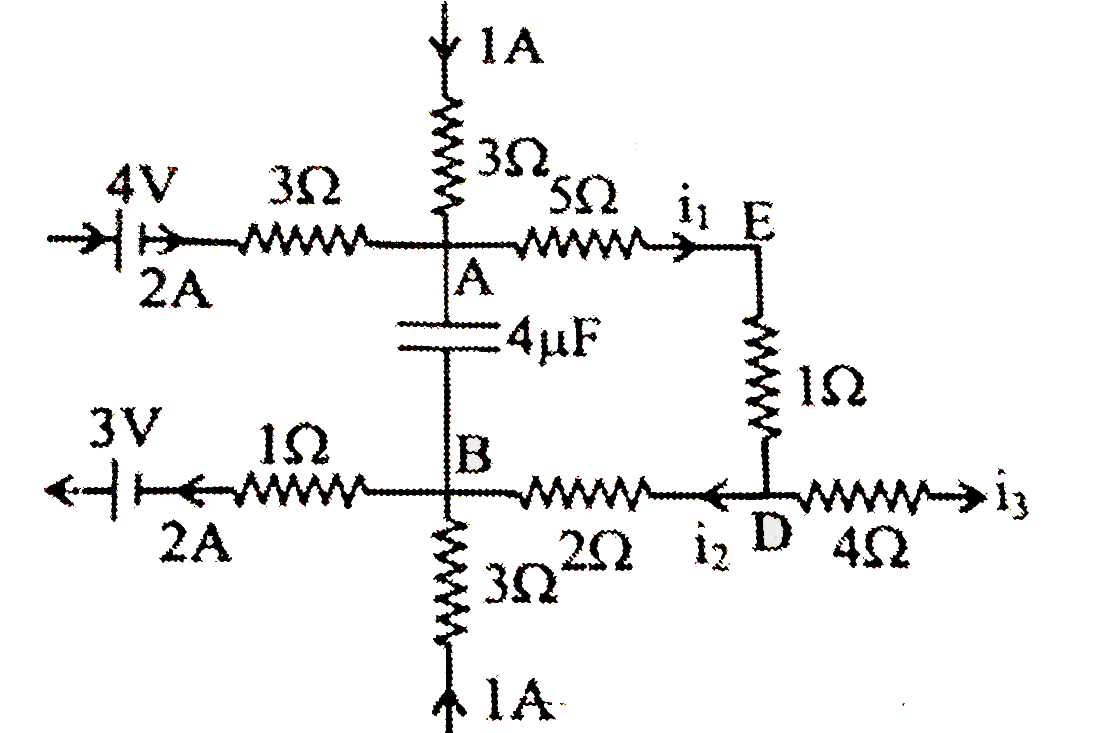
View SolutionThe figure shows a part of the circuit in the steady state. The currents, the valuces of resistances and emfs of the cells are shown in the figure. The circuit also contains a capacitor of capacitance `C=muF.` The value of `i_(1)` is-
View SolutionThe three resistance of equal value are arranged in the different combination shown below. Arrange them in increasing order of power dissipation.
(I)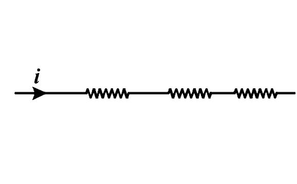 (II)
(II) 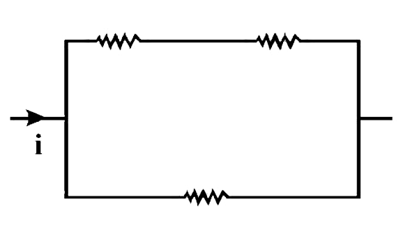
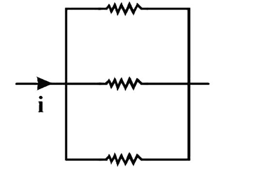 (IV)
(IV) 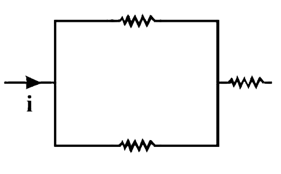
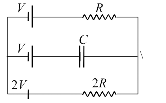
View SolutionIn the given circuit, with steady current, the potential drop across the capacitor must be
View SolutionIncandescent bulbs are designed by keeping in mind that the resistance of their filament increases with the increase in temperature. If at room temperature, `100W, 60W and 40W` bulbs have filament resistances `R_(100), R_(60) and R_(40)`, respectively, the relation between these resistances is
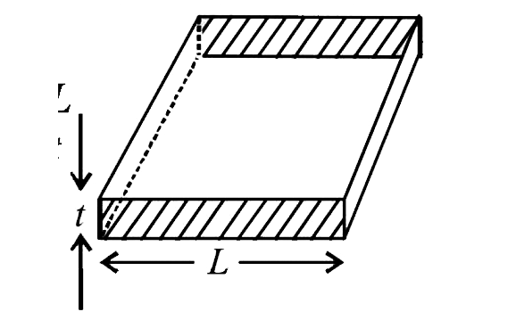
View SolutionConsider a thin square sheet of side L and thickness t, made of a material of resistivity `rho`. The resistance between two opposite faces, shown by the shaded areas in the figure is
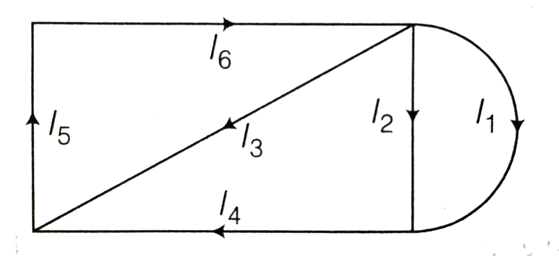
View SolutionIn the following network of 5 branches, the respective current are `l_(1),l_(2),l_(3)` etc. given that `l_(1)=-0.5A,l_(4)=1A` and `l_(5)=0.5A`, the remaining currents are
View SolutionTime taken by a 836 W heater to heat one litre of water from `10^@C to 40^@C` is
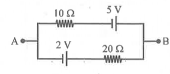
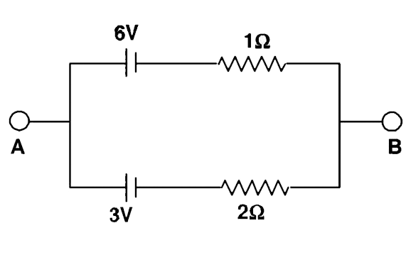
View SolutionTwo batteries of different emfs and different internal resistances are connected as shown. The voltage across AB in volts is.
 .
.
View SolutionFor resistances `10Omega, 10 Omega, 10 Omega and 15 Omega ` form a Wheatstone's network. What shunt is required across `15 Omega` resistor to balance the bridge ?
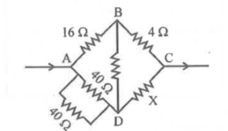
View SolutionIn the given circuit, the current in the arm BD is
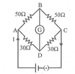
View SolutionIn the given circuit, the potential difference between the points A and B is
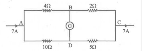
View SolutionThe Wheatstone's network is shown in the figure. If the key K is closed, then the galvanometer will
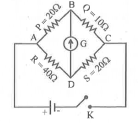
View SolutionFive resistances are joined as shown in the figure.
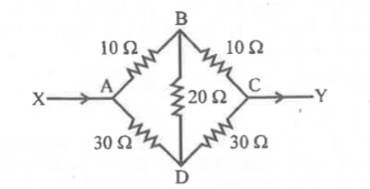
The equivalent resistance between the points X and Y is
View SolutionIn the given circuit, the potential difference between the points B and D is zero
The unknown resistance (X) is
View SolutionThe resistances in the left and right gaps of a metre bridge are `10 Omega and 30 Omega` respectively. If the bridge is balanced, then the distance of the null point from the centre of the wire is
View SolutionA circular coil has a resistance of `40 Omega`. Two points P and Q of the coil, which are one quarter of the circumference apart are connected to a 16 V battery, having an internal resistance of `0.5 Omega` ? What is the main current flowing in the circuit ?
View SolutionIn a metre bridge experiment, the balancing length from the left end is found to be 20 cm. If a standard resistance of 20 ohm is kept in the right gap, then the value of the unknown resistance in the left gap is
View SolutionTo find the resistance of a gold bangle, two diametrically opposite points of the bangle are connected to the two terminals of the left gap of a metre bridge. A resistance of `4 Omega` is introduced in the right gap. What is the resistance of the bangle if the null point is at 20 cm from the left end ?
View Solution5 resistances `R_(1), R_(2),R_(3),R_(4),R_(5)` are joined as shown in the figure.
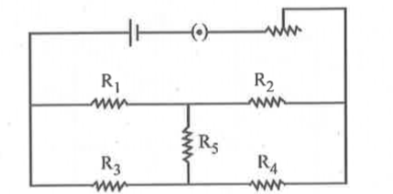
The values of `R_(1), R_(2), R_(3) and R_(4)` are so adjusted that the current in the circuit does not change for any value of the resistance `R_(5)`. This is possible for the following relation
View SolutionFigure`6.52` shows a balanced wheatstone network. Now, it is disturbed by changing `P` to `11 Omega`. Which of the following steps will not bring the bridge to balance again?
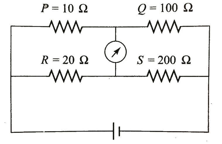
View SolutionIf `P=Q=R=10 Omega and S=20 Omega`, then what resistance should be joined with S to balance the wheatstone's network ?
View SolutionThe wheatstone's network is most sensitive when the ratio of its arms is
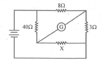
View SolutionIn the given circuit, the galvanometer G gives zero deflection. What is the value of resistance X ?
View SolutionTwo resistances are connected in the two gaps of a meter bridge. The balance point is `20 cm` from the zero end. When a resistance `15 Omega` is connected in series with the smaller of two resistance, the null point+ shifts to `40 cm`. The smaller of the two resistance has the value.
View SolutionFor resistances arranged to form a wheatstone's network are `10 Omega, 15 Omega, 6 Omega and 36 Omega`. What resistance should be connected across the `36 Omega` resistance to balance the bridge ?
View SolutionIn the given network, if the points B and D are connected by a copper wire, then the current in the wire will
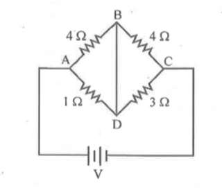
View SolutionAn unknown resistance `R_(1)` is connected is series with a resistance of `10 Omega`. This combination is connected to one gap of a meter bridge, while other gap is connected to another resistance `R_(2)`. The balance point is at `50 cm` Now , when the `10 Omega` resistance is removed, the balanced point shifts to `40 cm` Then the value of `R_(1)` is.
View SolutionThe resistance of each arm of the wheat stone bridge is `10Omega`. A resistance of `10Omega` is connected in series with galvanometer then the equivalent resistance across the battery will be:-
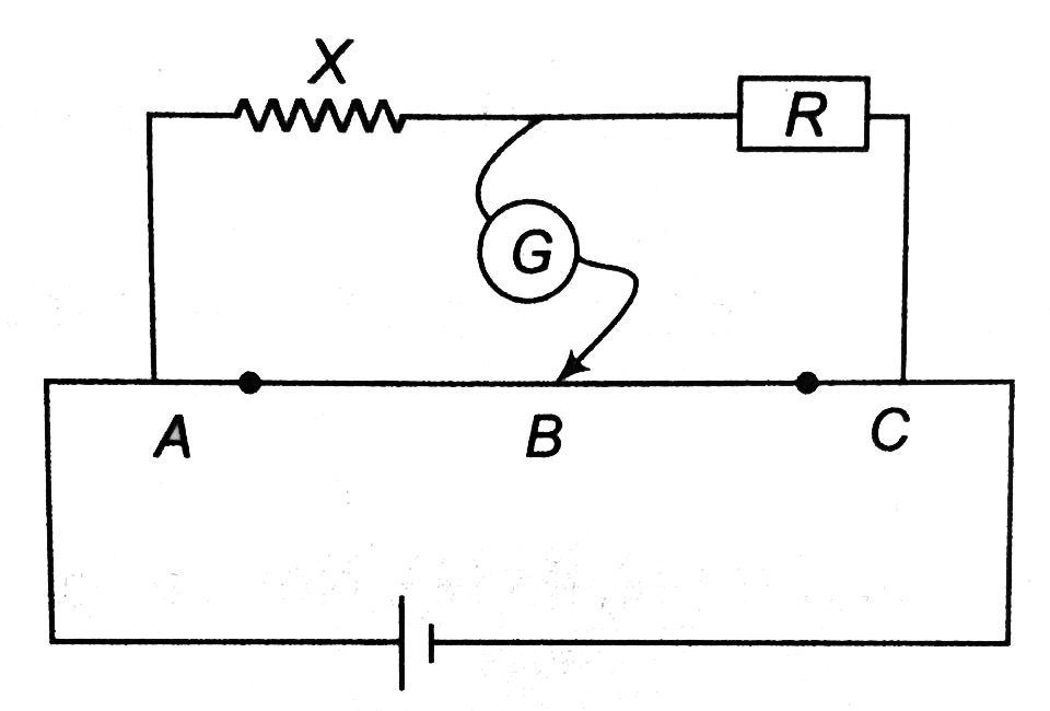
View Solution`R_(1),R_(2),R_(3)` are different values `R. A,B` and `C` are the null points obtained corresponding to `R_(1),R_(2) and R_(3)` respectively. For which resistor, the value of `R` will be the most accurate and why?
 .
.
View SolutionTwo resistances of values `20 Omega and 20 Omega` are introduced in the left and right gaps of a metre bridge. What is the shift in the null point if a resistance of `40 Omega` is connected in series with the resistance in the left gap ?
View SolutionWhat is the current in `10 Omega` resistance in the following network ?
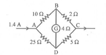
View SolutionIn the given circuit, when the galvanometer G shows no deflection, the current in the `5 Omega` resistance is ,
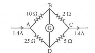
View SolutionIn a typical Wheatstone's network, the resistances in the cyclic order are `P=10 Omega, Q=5 Omega, S=4 Omega and R=4 Omega`. For balancing the bridge, a resistance of
View SolutionIn the following circuit, the current drawn from the battery is 2A. If the `5 Omega` resistance is replaced by a `20 Omega` resistor, then the current drawn from the battery will be
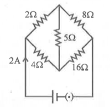
View SolutionIn the given circuit, the galvanometer will not show any deflection if the value of the resistance X is
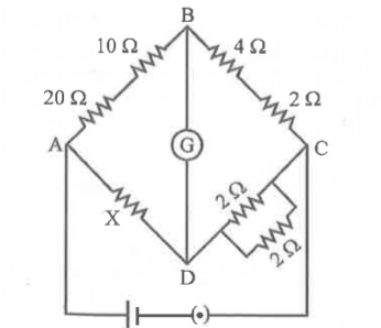
View SolutionA balanced Wheatstone's network is shown in the figure. If the balance is disturbed by changing P to `15 Omega`, then which one of the following steps will not bring the bridge to balance again ?
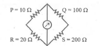
View SolutionResistance in the two gaps of a meter bridge are `10 ohm` and `30 ohm` respectively. If the resistances are interchanged he balance point shifts by
View SolutionA wire of length 3 m connected in the left gap of a metre bridge balances a `8 Omega` resistance in the right gap at a point, which divides the bridge wire in the ratio of `3 :2` . What is the length of the wire corresponding to a resistance of the length of the wire corresponding to a resistance of `1 Omega` ?
View Solution6 resistances, each of `4 Omega` are joined as shown in the figure. What is the equivalent resistance between A and B ?

View SolutionIn the given figure, when the galvanometer shows no deflection, the current (in amperes) flowing through the `5 Omega` resistance will be

View SolutionShown in the figure below is a meter- bridge set up will null deflection in the galvanometer.
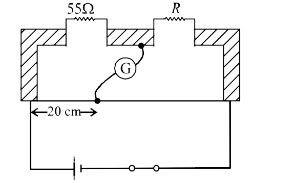
The value of the unknown resistor R is
View SolutionIf in the experiment of Wheatstone's bridge, the positions of cells and galvanometer are interchanged, then balance point will
View SolutionIn a Wheatstone's bridge, three resistances P,Q and R connected in the three arms and the fourth arm is formed by two resistances `S_1 and S_2` connected in parallel. The condition for the bridge to be balanced will be
View SolutionIn the given arrangement of the metre bridge, the null point is obtained at a distance x from the end A. What will be the distance of the null point from A, if the radius of the wire AB is doubled ?

View SolutionIn a meter bridge experiment, the null point is obtained at `20 cm`from one end of the wire when resistance `X` is balanced against another resistance `Y`. If `X lt Y`, then where will be the new position of the null point from the same end, if one decides to balanced a resistance of `4X` against `Y`?
View SolutionIn the circuit `P != R, ` the reading of the galvanometer is same with switch S open or closed. Then
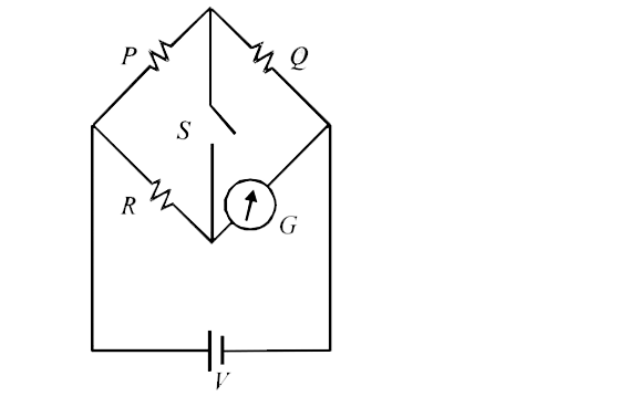
View SolutionA post office box is shown in figure. In order to calculate the value of an external resistance, it should be connected between

View SolutionIn the circuit shown, a metre bridge is in its balanced state. The metre bridge wire has a resistance 0.1 ohm/cm. What are the values of the unknown resistance X and the current drawn from the battery of negligible resistance ?

View SolutionEach of the resistance in the network shown in the figure is equal to R. The resistance between the terminals A and B is

View SolutionIn the following circuit, a conducing wire is connected between the terminals B and D, the current in the wire will
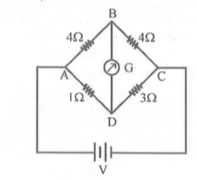
View SolutionIn the Wheatstone bridge shown below, in order to balance the bridge, we must have

View SolutionA metre bridge is set-up as shown in the figure to determine an unknown resistance 'X' using a standard 10 ohm resistor. The galvanometer shows null point when the tapping-key is at 52 cm mark. The end-correction are 1 cm and 2 cm respectively for the ends A and B. What is the value of 'X' ?

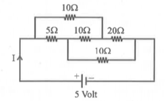
View SolutionIn the adjoining circuit, the current I drawn from the 5 volt source will be
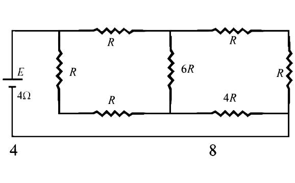
View SolutionA battery of internal resistance `4Omega` is connected to the network of resistance as shown . In order that the maximum power can be delivered to the network, the value of R in `Omega` should be
 .
.
View SolutionA uniform wire AB of length 1 m, an unknown resistance X and a resistance of `12 Omega` are connected to a battery and a galvanometer G as shown in the figure. The galvanometer shows no deflection when AJ=60 cm. What is the value of X (in ohm) ?
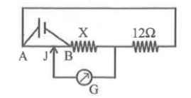
View SolutionThe resistances in left and right gap of a meter brigdge are 20 `omega` and 30 `omega` respecitively when the resistance in the left gap is reduced to half its value then balance point shifts by
View SolutionThe resistance in the two arms of the metre bridge are `5 Omega and R Omega`, respectively. When the resistance R is shunted with an equal resistance, the new balance point is at `1.6l_(1)` . The resistance R is

View SolutionIn a typical wheatstone network, the resistances in cyclic order are `A=10 Omega, B=5 Omega, D =4 Omega and C=4 Omega`. For the bridge to be balanced

View SolutionWhat is the equivalent resistance between the points P and Q in the network shown in the figure ?

View SolutionA cell of e.m.f. of 1.08 V is balanced by a 216 cm length of a potentiometer. What is the length of the wire that would balance a cell of e.m.f. 1.5 V ?
View SolutionIn a potentiometer experiment, the null point is obtained at 140 cm for a cell of e.m.f. 1.2 V. With another cell of unknown e.m.f., the null point is obtained at 210 cm. The unknown e.m.f. is
View SolutionIn a potentiometer experiment, the balancing length is found to be 1.8 m for a cell of e.m.f. 1.5 V. What is the balancing length for a cell of e.m.f. 1 V ?
View SolutionTwo cells of e.m.f.'s `E_(1) and E_(2)` where `E_(1) gt E_(2)`, are connected in series so as to assist each other, the balancing length is 2.7m . When the cells are connected in series so as to oppose each other, the balancing length is found to be 0.3m . What is the ratio of their e.m.f.'s ?
View SolutionA cell of e.m.f. 1.2 V is balanced by 150 cm of potentiometer wire. When the cell is shunted by a resistance of `4 Omega`, the balancing length is reduced by 30 cm. What is the internal resistance of the cell ?
View SolutionA potentiometer wire of length 400 cm has a resistance of `8 Omega`. If a potential gradient of 0.5 V/m is maintained throughout the length of the wire, then the current flowing through the wire is
View SolutionA potentiometer wire is 10 m long and a P.D. of 6 V is maintained between its ends. The e.m.f. of the cell which balances against a length of 200 cm of the potentiometer wire is
View SolutionA potentiometer wire has a length 2 m and resistance of `10 Omega`. It is coonnected in series with a resistance of `990 Omega` and a cell of e.m.f. 2 V. The potential gradient along the wire is
View SolutionA cell of e.m.f. 2 V and negligible internal resistance is connected to a potentiometer wire of resistance `10 Omega` and length 4 m. The potential difference per unit length (potential gradient ) of the wire is
View SolutionAs is the cross sectional area and `rho` is the specific resistance of a potentiometer wire. If I is the current passing through the potentiometer wire, then the potential gradient along the length of the wire is given by
View SolutionA potentiometer experiment is set up to compare the e.m.f.'s `E_(1) and E_(2)` of two cells. When the null point is obtained, the current is drawn from
View SolutionA cell of e.m.f. 4 V and of negligible internal resistance is connected in series with a potentiometer wire of length 400 cm. The e.m.f. of a Leelanche cell is found to be balacned at 150 cm from the positive end of the potentiometer wire. What is the e.m.f. of the Leclanche cell ?
View SolutionA 10 m long wire ofresistance `20 Omega` is connected in series with battery of EMF `3V` and negligible internal resistance and a resistance of `10 Omega`. The potential gradient along the wire is :
View Solution
MCQ questions and complete solutions for chapter CURRENT ELECTRICITY of MARVEL PHYSICS (HINGLISH) of Class 12