Complete Solutions to Ac Voltage Applied To A Series Lcr Circuit of chapter ALTERNATING CURRENT of Class 12 book with complete answers and questions
| Class 12 | PHYSICS |
| Chapter | ALTERNATING CURRENT |
| NCERT FINGERTIPS | Ac Voltage Applied To A Series Lcr Circuit |
| Number Of Questions | 28 |
| Academic Year | 2023-24 |
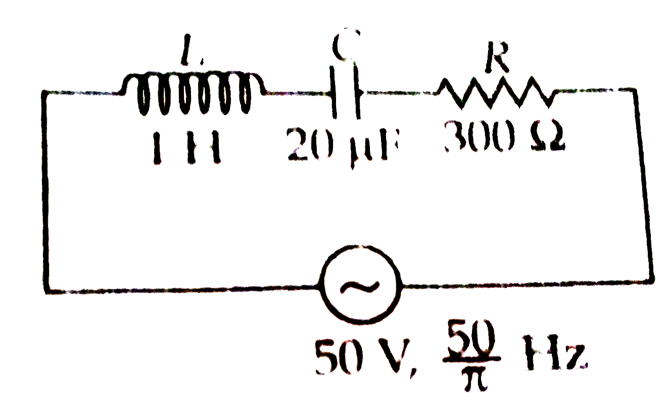
In the circuit shown in figure, what will be the reading of the voltmeter ?

View SolutionIn the series LCR circuit shown the impedance is

View SolutionA circuit containing a `20 Omega` resistor and `0.1 mu F` capacitor in series is connected to 320 V ac supply of angular frequency `100 " rad " s^(-1)`. The impedance of the circuit is
View SolutionA `0.2 k Omega` resistor and `15 mu F` capacitor are connected in series to a 220 V, 50 Hz ac source. The impedance of the circuit is
View SolutionAs the frequency of an ac circuit increases, the current first increases and then decreases. What combination of circuit elements is most likely to comprise the circuit ?
View SolutionA circuit consists of a resistance 10 ohm and a capacitance of `0.1 mu F` If an alternating e.m.f. of 100 V. 50 Hz is applied, calculate the current in the circuit.
View Solution200 V ac source is fed to series LCR circuit having `X_(L)=50 Omega, X_(C )=50 Omega` and `R = 25 Omega`. Potential drop across the inductor is
View SolutionA `100 mu F` capacitor in series with a `40 Omega` resistor is connected to a 100 V, 60 Hz supply. The maximum current in the circuit is
View SolutionIn the question number 42, the time lag between the current maximum and the voltage maximum is
View SolutionIn series LCR circuit, the phase angle between supply voltage and current is
View SolutionIn the question number 44, the phase difference between the voltage across the source and current is
View SolutionA sinusoidal voltage of peak value 293 V and frequency 50 Hz is applie to a series LCR circuit in which `R=6 Omega, L=25 mH` and `C=750mu F`. The impedance of the circuit is
View SolutionA pure resistive circuit element X when connected to an ac supply of peak voltage 200 V gives a peak current of 5 A which is in phase with the voltage. A second circuit element Y, when connected to the same ac supply also gives the same value of peak current but the current lags behind by `90^(@)`. If the series combination of X and Y is connected to the same supply, what will be the rms value of current?
View SolutionAn LCR series ac circuit is at resonance with 10 V each across L, C and R. If the resistance is halved, the respective voltage across L, C and R are
View SolutionIn a series LCR circuit the voltage across an inductor, capacitor and resistor are 20 V, 20 V and 40 V respectively. The phase difference between the applied voltage and the current in the circuit is
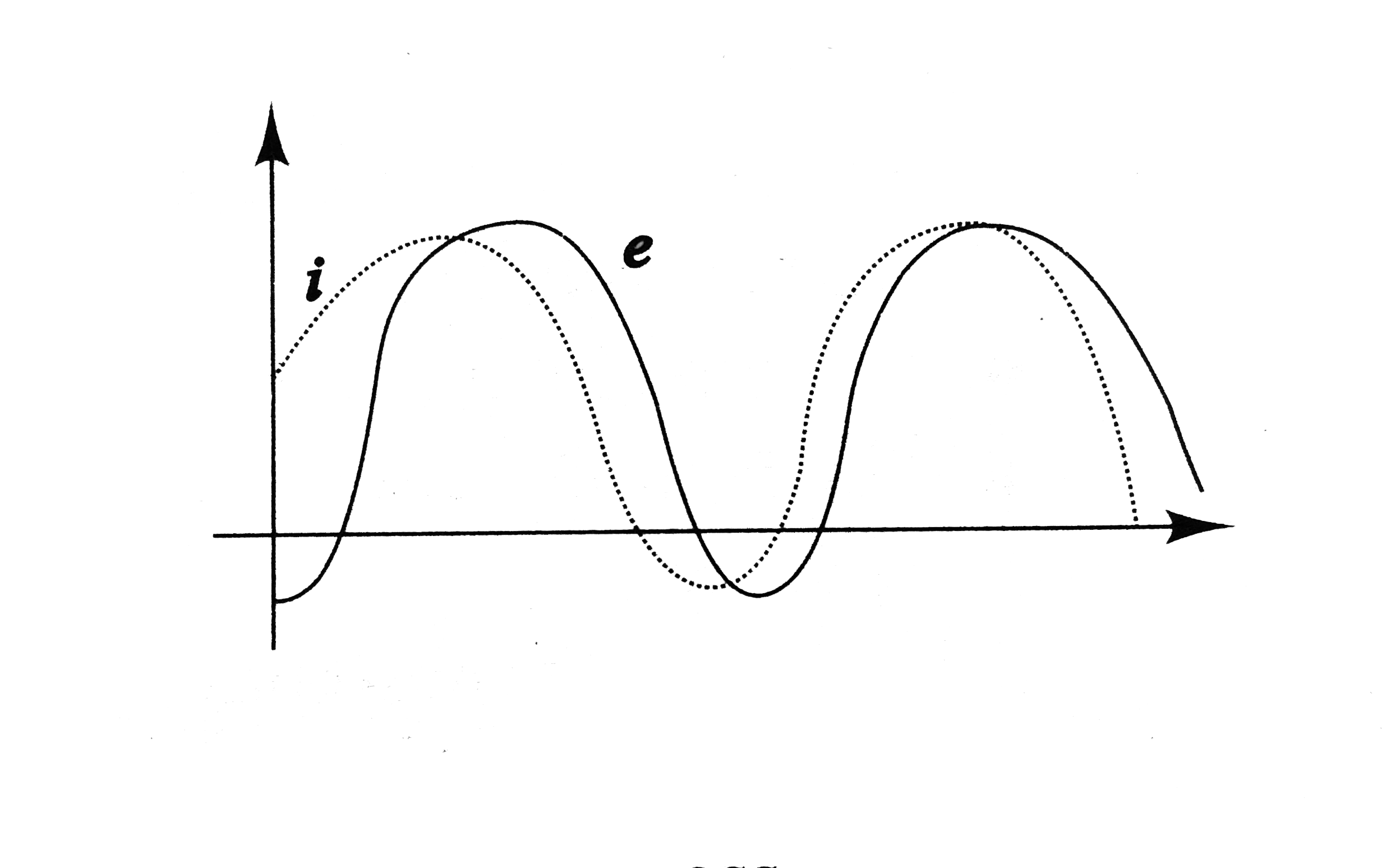
View SolutionWhen an ac source of emf`e=E_(0) sin (100 t)` is connected across a circuit, the phase difference between emf e and currnet I in the circuit is observed to be `(pi)//(4)` as shown in fig. If the circuit consists possibly only of R-C or R-C of L-R series, find the relationship find the relationship between the two elements.

View SolutionIn a circuit `L, C` and `R` are connected in series with an alternating voltage source of frequency `f`. The current lead the voltages by `45^(@)`. The value of `C` is :
View SolutionAt resonance frequency the impedance in series LCR circuit is
View SolutionAn LCR series circuit is under resonance. If `I_(m)` is current amplitude, `V_(m)` is voltage amplitude, R is the resistance, Z is the impedance, `X_(L)` is the inductive reactance and `X_(C )` is the capacitive reactance, then
View SolutionAt resonant frequency the current amplitude in series LCR circuit is
View SolutionThe resonant frequency of a series LCR circuit with `L=2.0 H,C =32 muF` and `R=10 Omega` is
View SolutionObtain the resonant frequency `(omega_(r))` of a series LCR circuit withL = 2.0 H, C = 32 `muF` and R = 10 ohm. What is the Q value of this circuit ?
View SolutionFigure shows a series LCR circuit connected to a variable frequency 230 V source.

The source frequency which drives the circuit the circuit in resonance is
View SolutionA series LCR circuit has `R=5 Omega, L=40 mH` and `C=1mu F`, the bandwidth of the circuit is
View SolutionIn LCR - circuit if resistance increases, quality factor
View SolutionIn a series LCCR circuit having `L=30 mH, R=8 Omega` and the resonant frequency is 50 Hz. The quality factor of the circuit is
View SolutionA series resonant LCR circuit has a quality factor (Q-factor)=0.4. If `R=2k Omega, C=0.1 mu F` then the value of inductance is
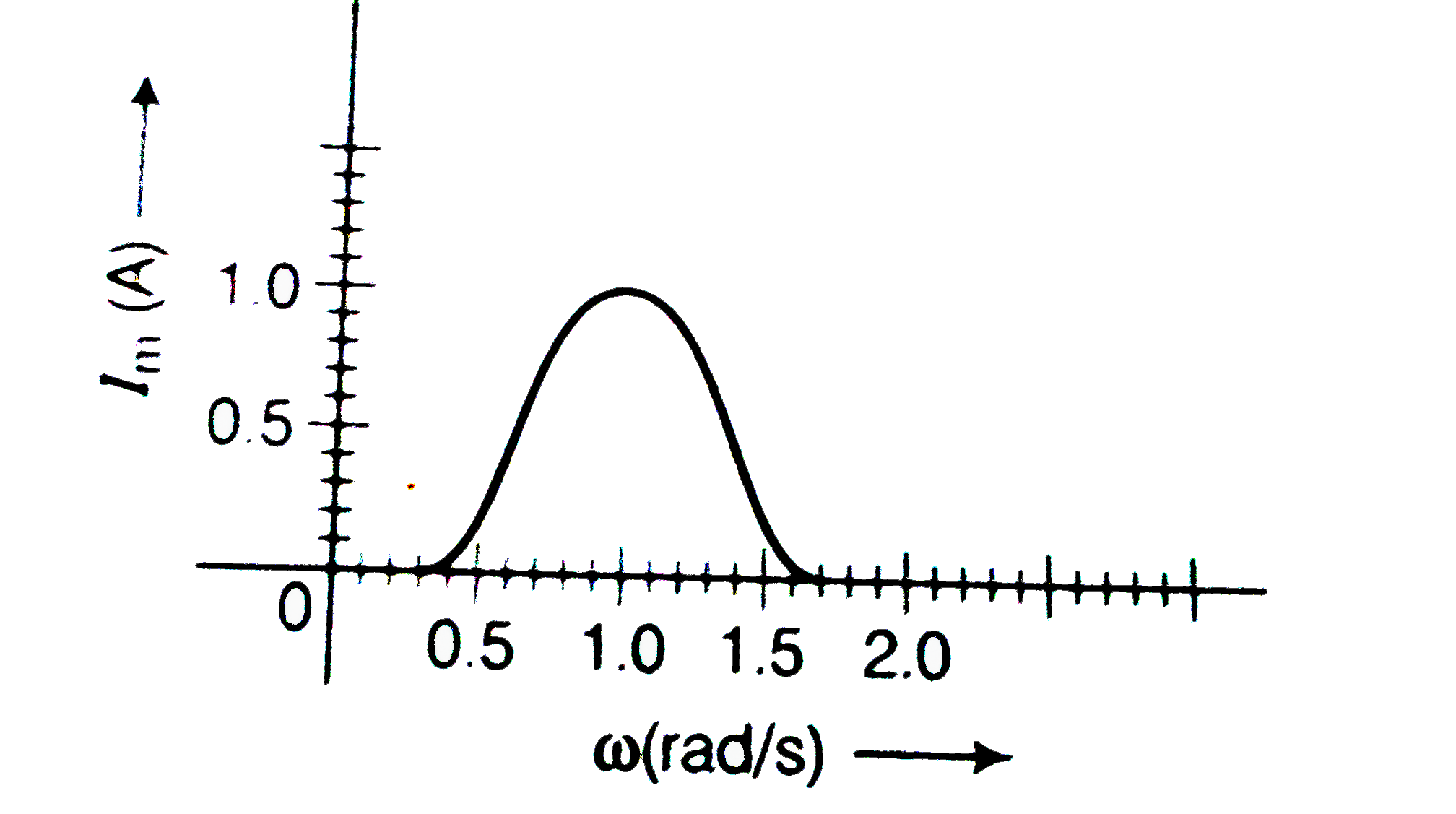
View SolutionIn series LCR circuit, the plot of `I_("max")` versus `omega` is shown in figure. Find the bandwith and mark in the figure.

View Solution
Ac Voltage Applied To A Series Lcr Circuit questions and complete solutions for chapter ALTERNATING CURRENT of NCERT FINGERTIPS PHYSICS (HINGLISH) of Class 12