Complete Solutions to All Questions of chapter CURRENT ELECTRICITY of Class 12 book with complete answers and questions
| Class 12 | PHYSICS |
| Chapter | CURRENT ELECTRICITY |
| PHYSICS GALAXY | All Questions |
| Number Of Questions | 100 |
| Academic Year | 2023-24 |
Find the velocity of charge leading to `1A` current which flows in a copper conductor of cross section `1cm^2` and length `10 km`. Free electron density of copper is `8.5x10^28//m^3`. How long will it take the electric charge to travel from one end of the conductor to the other?
03:51View SolutionThe potential difference across a straight wire of `10^(-3) cm^(2)` cross sectional area and 50cm length is 2V, when a current of 0.25A flows in the wire. Calculate.
(a) The field strength is the wire
(b) The current density and
(c) The conductivity of the metal04:43View SolutionFind the total linear momentum of the electrons in a conductor of length `l = 1000m` carrying a current `I = 70A`.
02:43View SolutionTwo large parallel metal plartes are located in vacuum. One of these serves as a cathode, a source of electrons with negligible initial speed. An electron flow directed toward the opposite plate produces a space charge causing the potential in the gap between the plate to very as `V=ax^(4//3)`, where a is a positive constant, and x is the distance from the cathode. find:
(a) The volume density of space charge as a function of x
(b) The current density08:04View SolutionA copper wire has a square cross section of 6 mm on a side. The wire is 10 m long and carries a current of 3.6A. The density of free electrons is `8.5xx10^(28)//m^3.`Find the magnitude of (a) the current density in the wire , (b) the electric field in the wire. (c ) How much time is required for an electron to travel the length of the wire? `(rho, "electrical resistivity, is " 1.72 xx10^(-8) Omegam.)`
06:31View SolutionHow many electrons per second pass through a section of resistance of `20Omega` across which a potential difference of 64V is applied.
02:15View Solution`1` meter long metallic wire is broken into two unequal parts `P and Q. P` part of the wire in uniformly extended into another wire `R`. Length of `R` is twice the length of `P` and the resistance of `R` is equal to that of `Q`. Find the ratio of the resistance `P` and `R` and also the ratio of the length `P and Q`
04:50View SolutionThe area of cross-section, length and density of a piece of a metal of atomic weight `60` are `10^-6 m^2`, `1.0 m` and `5xx10^3 kg//m^3` respectively,every atom contributes one free electron. (Given Avogadro number `=6xx10^23//mol)`. Find the drift velocity of electrons in the metal when the current of `16A` passes through:
05:27View SolutionFind equivalent resistant across terminals A and B in the circuit shown in figure-3.30.
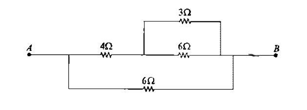 02:46View Solution
Find equivalent resistance of the circuit shown in figure 3.32 across terminals A and B.
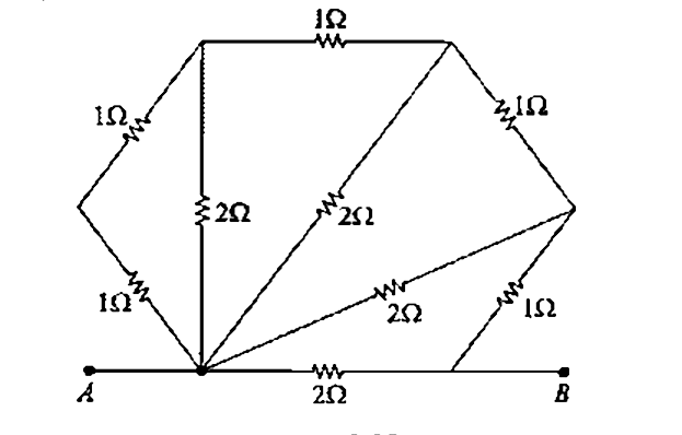 02:56View Solution
Calculate battery current and equivalent resistance of the network shown in figure.
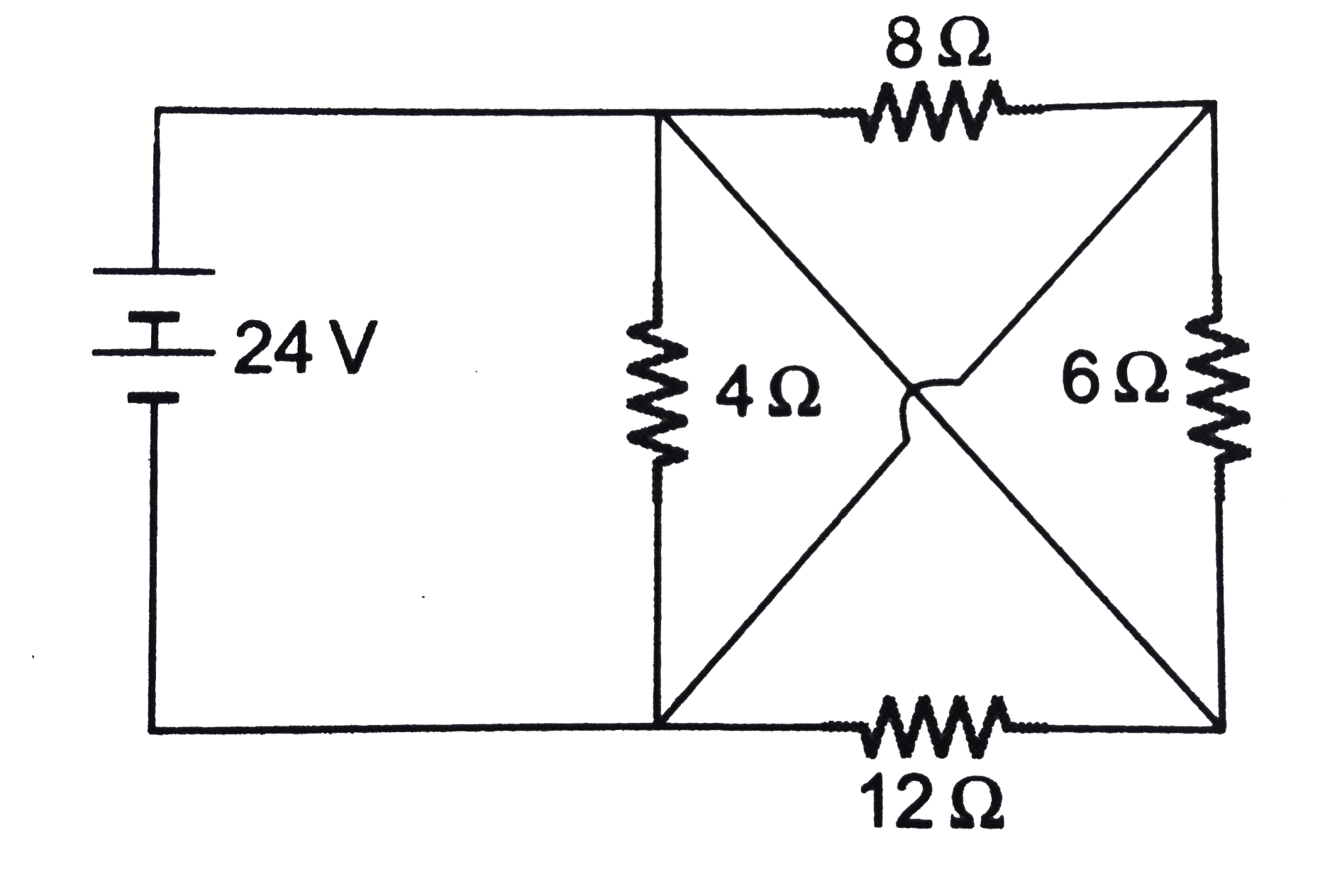 02:59View Solution
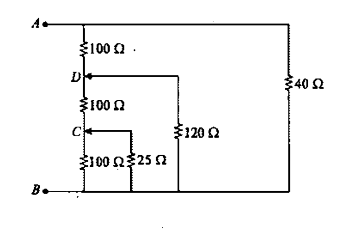
A long resistor between point A and B as shown in figure-3.35 has reisistance of `300 Omega` and is tapped at one thrid points.
(a) What is equivalent resistance between A and B
(b) If the potential difference between A and B is 320V, what will be the potential difference between B and C.
(c) Will this change if the `40Omega` resistor is disconnected?
 08:54View Solution
You need to produce a set of cylindrical copper wires 2.5 m long that will have a resistance of `0.125Omega` each. What will be the mass of each of these wires? (Density of copper is `8.9xx10^3 kgm^(-3)` and resistivity of copper is `1.72 xx10^(-8) OmegaM).`
05:00View SolutionTwo resistors with temperature coefficients of resistance `alpha_1` and `alpha_2` have resistances `R_(01)` and `R_(02) ` at `0^@C`. Find the temperature coefficient of the compound resistor consisting of the two resistors connected.
a.. In series and
b. in paralllel08:05View SolutionTwo coils connected in series have resistance of `600K Omega` and `300 Omega` at `20^@C` and temperature coefficient of` 0.001` and `0.004 (.^@C)^-1` respectively. Find resistance of the combination at a temperature of `50^@C`. What is the effective temperature coefficient of combination?
05:04View SolutionShown a conductor of length `l` having a circular cross section. The radius of cross section varies linearly form `a to b`. The resistivity of the material is`(rho)`.Assuming that `b-altltl`,find the resistance of the conductor.
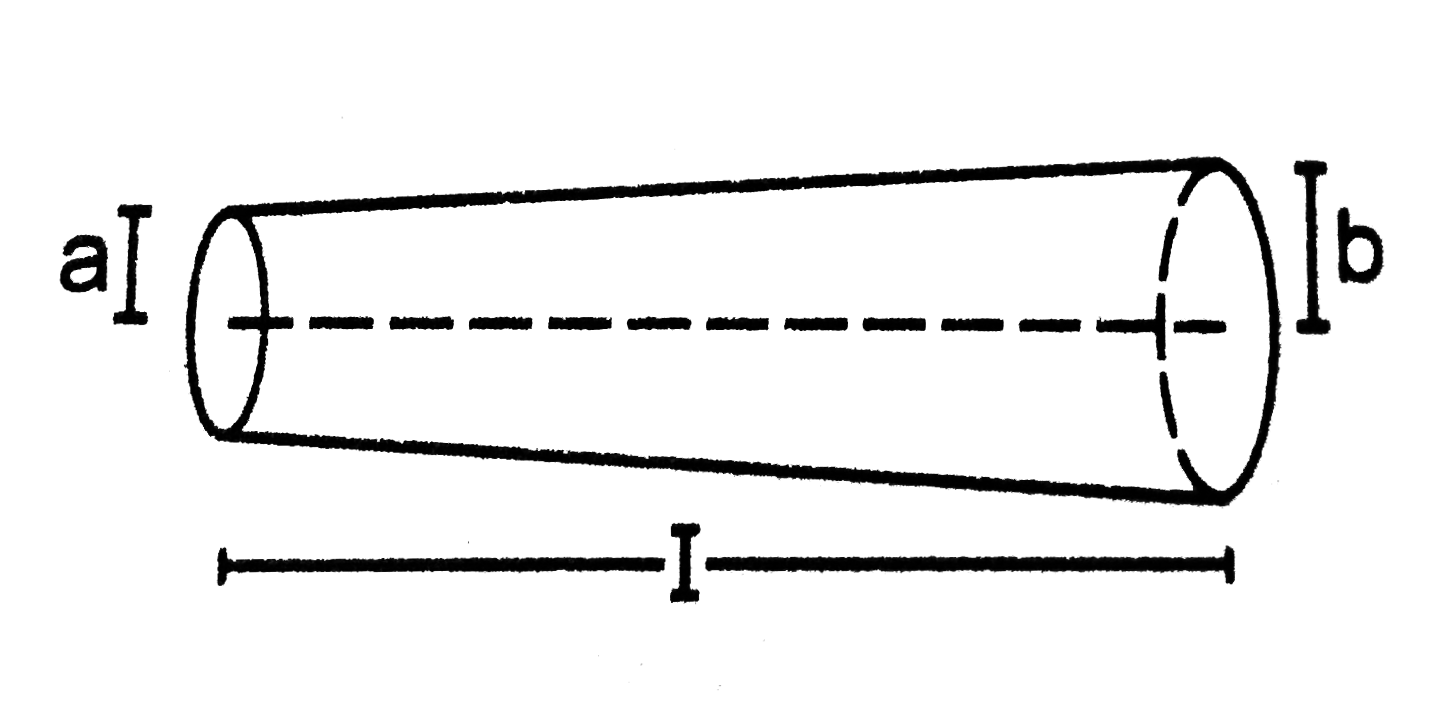 08:43View Solution
ABCD is a square where each side is a uniform wire of resistance `1Omega.` A point E lies on CD such that if a uniform wire of resistance `1Omega` is connected across AE and constant potential difference is applied across A and C, then B and E are equipotential. Then,
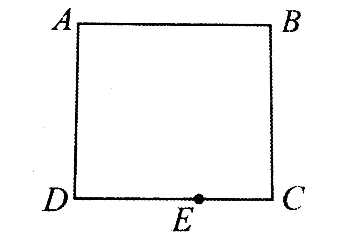 12:39View Solution
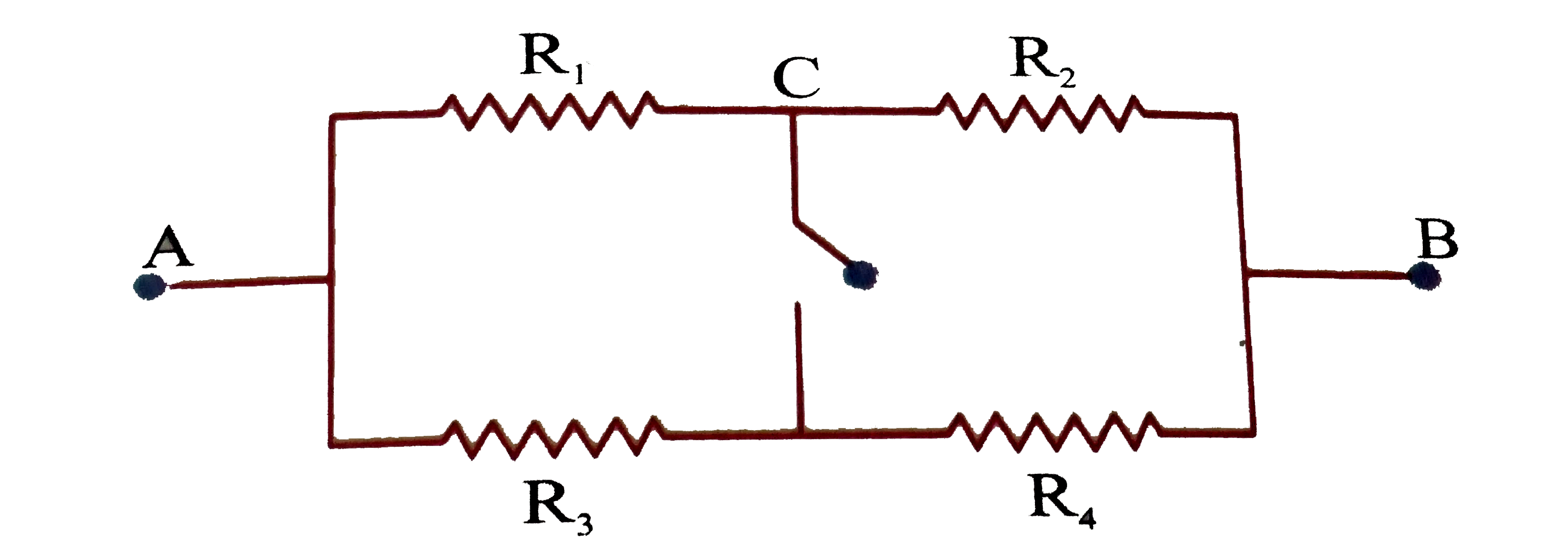
Four resistors `R_(1),R_(2),R_(3)` and `R_(4)` are connected between two terminals A and B iin a network as shown in the diagram. A key K can connect the two points (see diagram) C and D. A constant potential difference `(V_(A)-V_(B))=V` is maintained between thhe points A and B
Q. If `V=25,R_(1)=1Omega,R_(2)=2Omega,R_(3)=3Omega` and `R_(4)=4Omega` the current that will flow from C to D on connecting key K is05:21View SolutionIn fig the steady state current in `2omega` resistance is
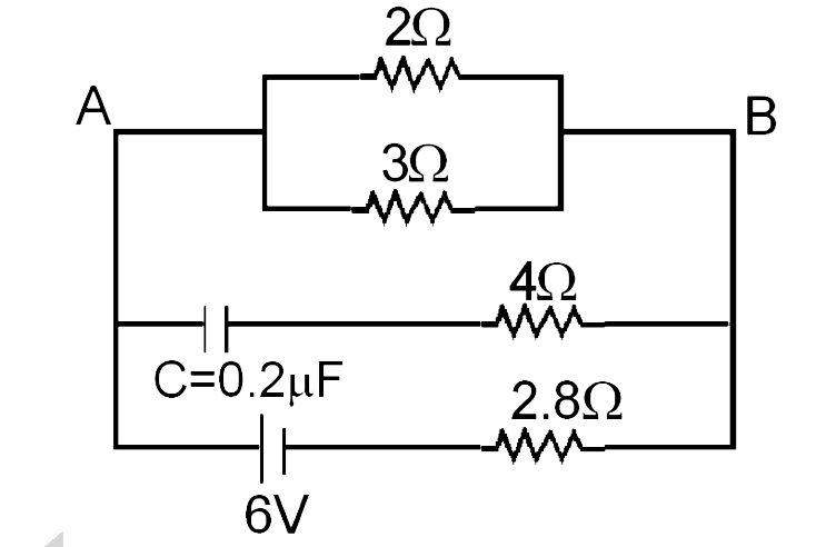 02:20View Solution
Find the equivalent resistance and current in `6Omega` resistance in the circuit shown in figure 3.55.
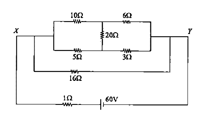 08:49View Solution
In a Wheatstone's bridge a battery of 2V is used all shown in figure-3.56. find the value of the current through the middle branch in the unbalanced condition of the bridge when P`=1Omega,Q=2Omega,R=2Omega` and `S=3Omega` and resistance of middle branch BD is `4Omega`
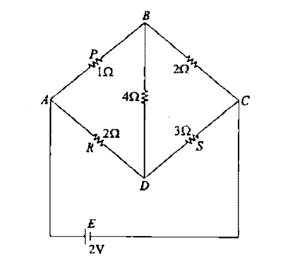 08:19View Solution
Find the equivalent resistance across the terminals A and B in the circuit shown in figure-3.76. Each resistance in circuit is R.
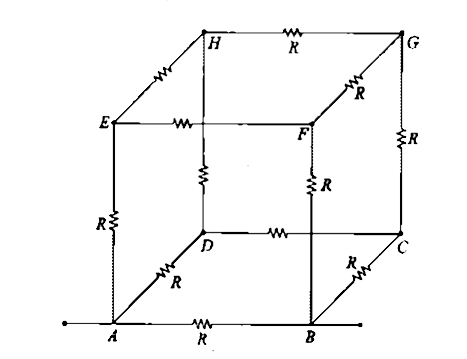 12:40View Solution
Find the equivalent resistance across the terminals A and B in the circuit shown in figure-3.76. Each resistance in circuit is R.
 12:40View Solution
Find the equivalent resistance across the terminals A and B in the cirucit shown in figure-3.76. Each resistance in circuit is R.
 12:40View Solution
Find the equivalent resistance across terminals A and B as shown in figure-3.78. Each resistance in circuit is R.
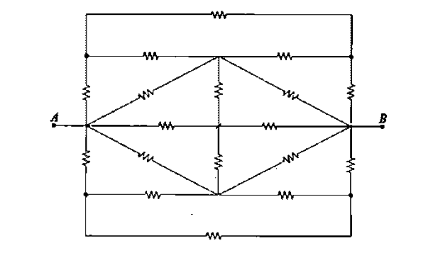 12:28View Solution
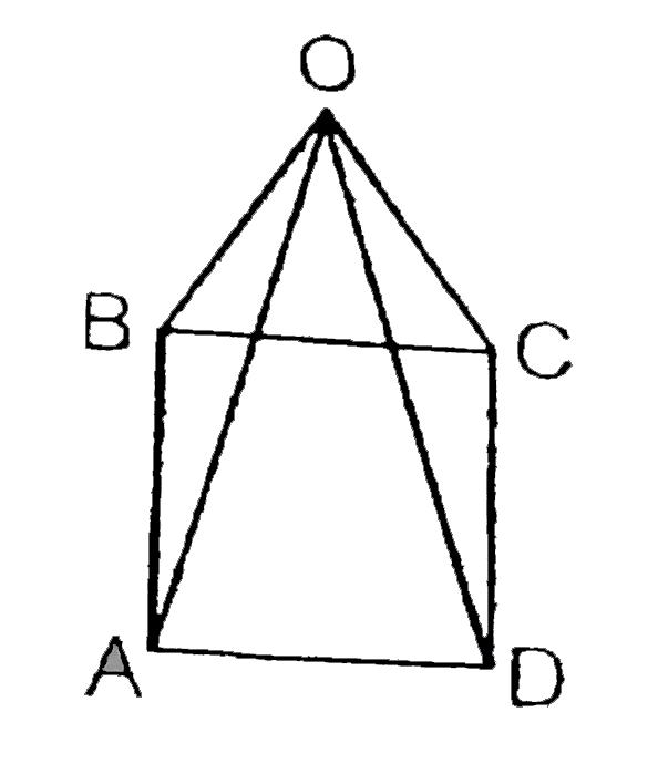
Eight identical resistance each `15Omega` are connected along the edge of a pyramid having square base as shown. Find the equivalent resistance between A and D in `Omega`04:10View SolutionIn the circuit shown in figure. 3.82 find the current through battery and current in `8Omega` resistances.
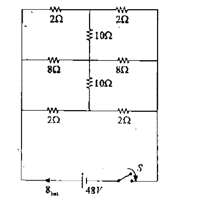 05:34View Solution
What is the equivalent resistance between the terminal points A and B in the cirucit shown in figure-3.84
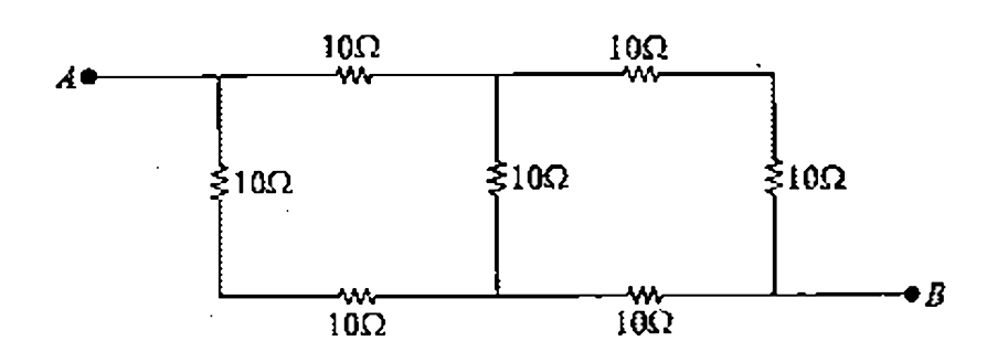 09:24View Solution
Find the equivalent resistance of the infinite ladder circuit shown in figure-3.86 across terminals A and B .
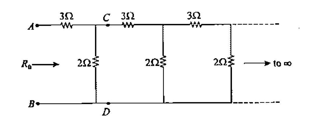 05:51View Solution
In the circuit shown in figure find the potentials of `A,B,C` and `D` and the current through `1Omega` and `2Omega` resistance.
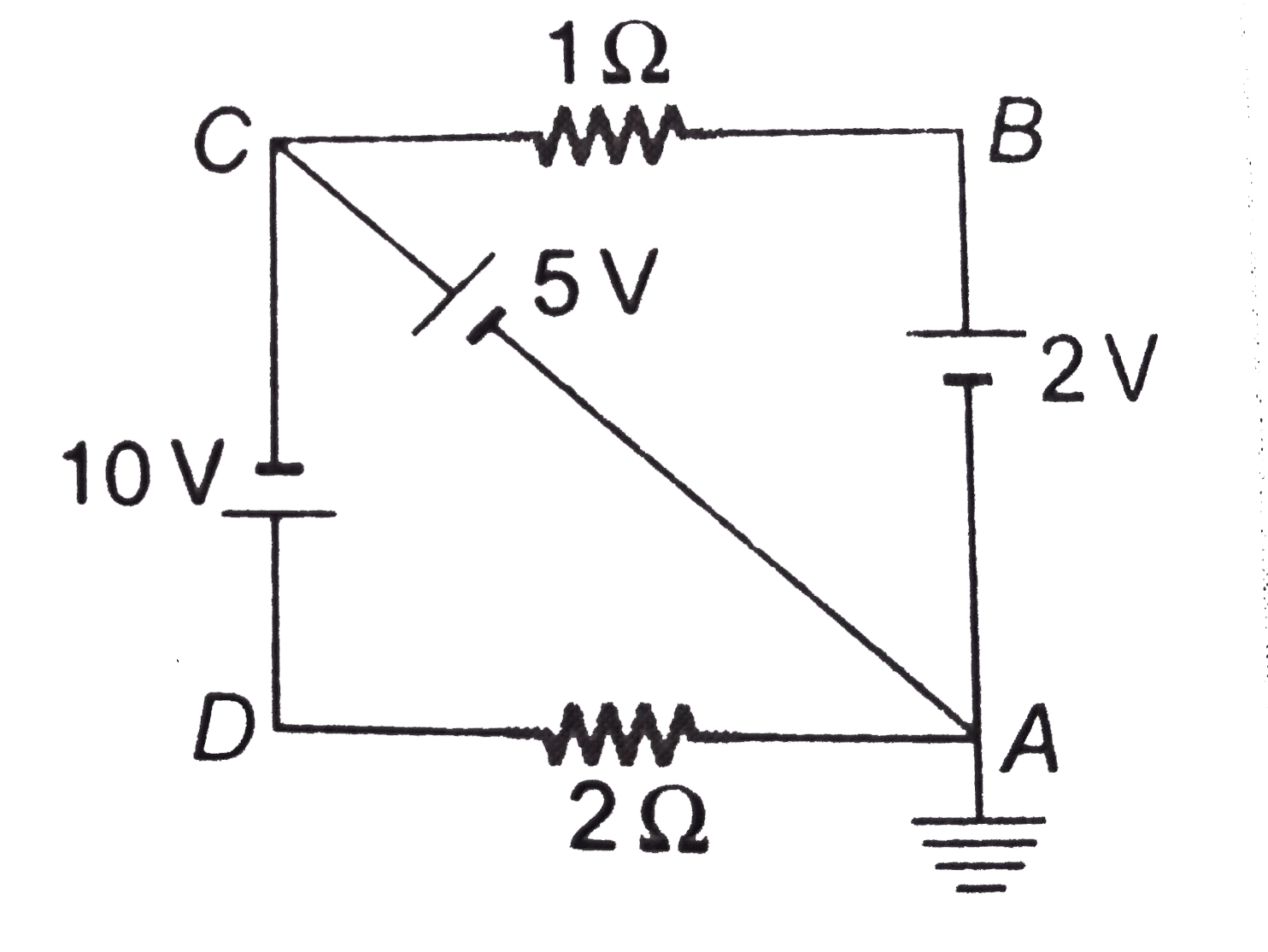 03:41View Solution
Find the current flowing through the resistance `R_(1)` of the circuit shown in figure-3.103. the resistances are equal to `R_(1)=10Omega,R_(2)=20Omega` and `R_(3)=30Omega` and the potentials of points 1,2 and 3 are given as `V_(1)=10V,V_(2)=6V` and `V_(3)=5V`.
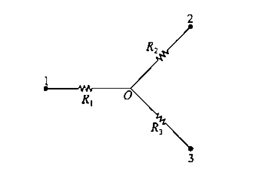 06:47View Solution
In figure-3.105, if the potential at point P is 100V, what is the potential at point Q?
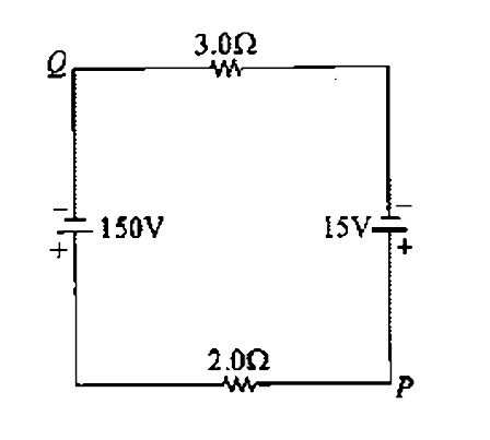 03:40View Solution
Three 4V batteries are connected with resistance `0.1Omega,0.2Omega` and `0.3Omega` are connected in series with a `2.045Omega` resistor as shown in figure-3.106. Find current in `2.045Omega` resistance.
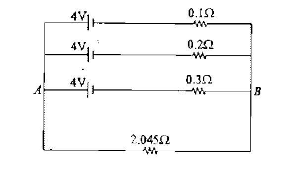 07:00View Solution
Find the current in `4Omega` resistance in circuit shown in figure-3.108.
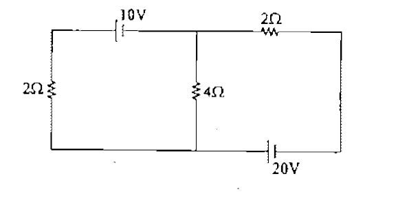 03:15View Solution
Two sources of current of equal emf are connected in series and having different internal resistance `r_1` and `r_2(r_2gtr_1)`. Find the external resistance `R` at which the potential difference across the terminals of one of the sources becomes equal to zero.
04:33View SolutionTwelve cells each having the same e.m.f are connected in series and are kept to a closed box. Some of the cell are connected in reverse order .The battery is connected in series with an ammeter an external resistance `R` and two cells of the same type as an in the battery .The current when they and support each other is `3` ampere and current is `2` ampare when the two oppose each other. How many cells are connected in servese order ?
06:25View SolutionThe `n` rows each containinig `m` cells in series are joined parallel. Maximum current is taken from this combination across jan external resistance of `3 Omega` resistance. If the total number of cells used are 24 and internal resistance of each cell is `0.5 Omega` then
02:17View SolutionA galvanometer, together with an unknown resistance in series, is connected across two identical batteries of each `1.5 V`. When the batteries are connected in series,the galvanometer records a current of `1 A`, and when the batteries are connected in parallel, the current is `0.6 A`. In this case, the internal resistance of the battery is `1//'**' Omega`.
What is the value of '*'?05:26View SolutionThe potential difference across the terminals of a battery is `8.4 V` when there is a current of `1.50 A` in the battery from the negative to the positive terminal. When the current is `3.50 A`in, the reverse direction, the potential difference becomes `9.4 V`.
(a) What is the internal resistance of the battery?
(b) What is the emf of the battery?04:30View SolutionFind the current in `6Omega` resistance in the circuit shown in figure-3.135 using Kirchhoff's voltage Law.
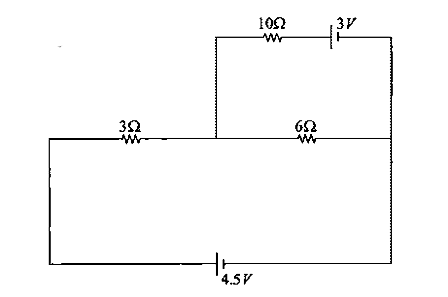 03:42View Solution
Two cells of EMF 1.5V and 2.0V and internal resistances `2Omega` and `1Omega respevitvely, have their negative terminals joined by a wire of `6Omega` and positive terminals by another `4Omega`. A third resistance of `8Omega` is connected to the midpoints of these two wires. find the potential difference at the ends of the thrid wire
06:45View SolutionFind out the potential difference between points x and y in the figure shown-3.138
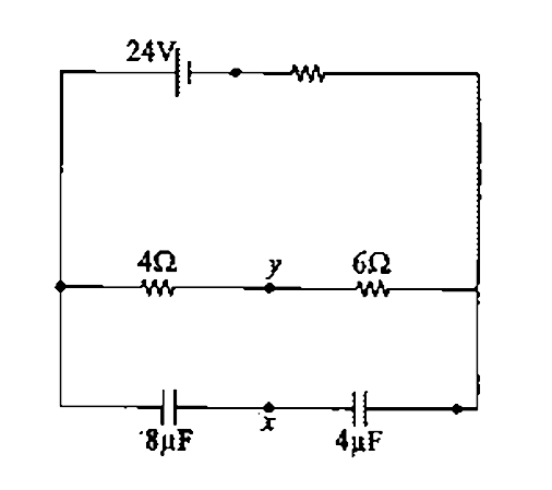 03:05View Solution
`N` sources of current with different emf's are connected as shown in Fig. The emf of the sources are proportional to their internal resistancs, i.e., `E = alpha R`, where `alpha` is an assigned constatant. The lead wire resistance is neglible. Find:
(a) the current in the circuit ,
(b) the potential differences between points `A` and `B` dividing the circuit in `n` and `N- n` links.
 03:12View Solution
In the circuit shown in figure 3.141, find the energy stored in `4muF` capacitor in steady state.
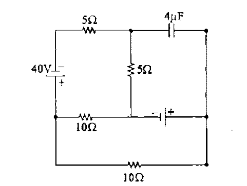 07:00View Solution
In the figure shown -3.143, find ratio of charges on `4muF` and `2muF` capacitors in steady state.
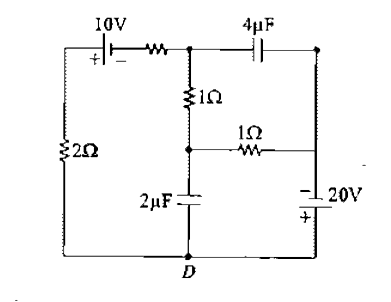 07:59View Solution
Find the magnitude and direction of the current flowing through the resistance `R` in the circuit shown in Fig. if the emf's of the sources are equal to `E_(1) = 1.5 V` and `E_(2) = 3.7 V` and the resistances are equal to `R_(1) = 10 Omega, R_(2) = 20 Omega , R = 5.0 Omega`. The internal resistances of the sources are neglible.
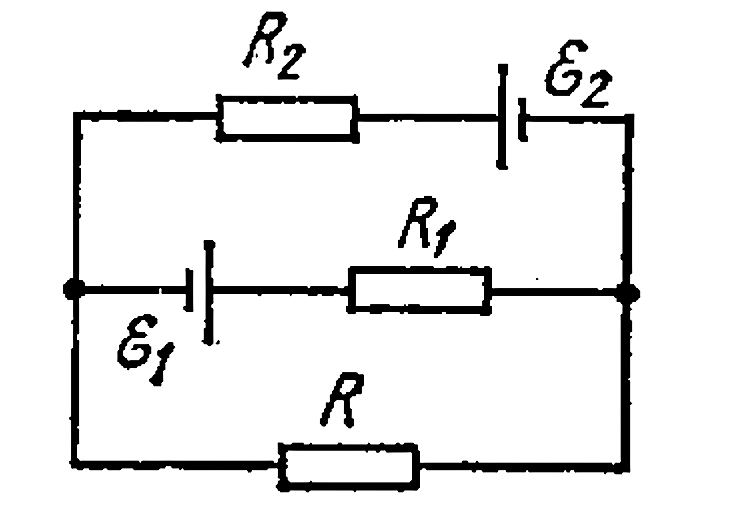 04:55View Solution
Find the current flowing thorugh battery and charger on capacitor in steady state.
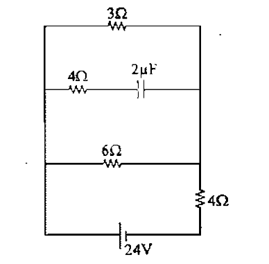 05:16View Solution
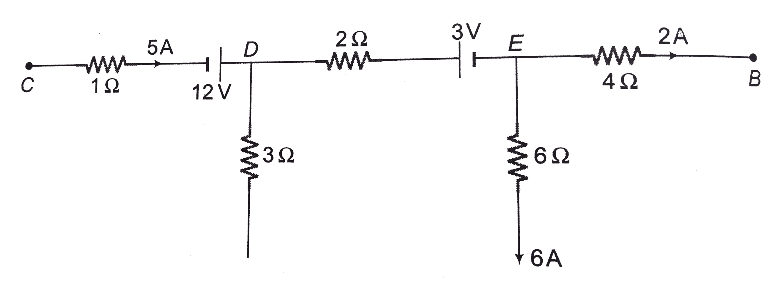 Figure shows the part of a circuit. Calculate the power dissipated in `3omega` resistance. What is the potential difference `V_C-V_B?`03:47View Solution
In the circuit shown in figure potential difference between the points `A` and `B` in the steady state is
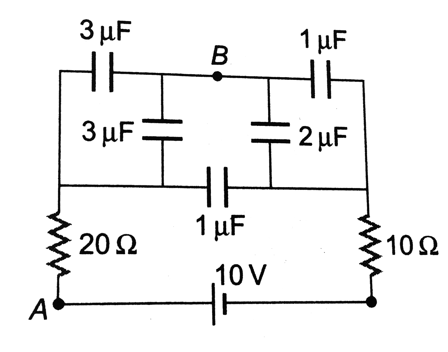 08:17View Solution
Find a potential difference `varphi_(A) - varphi_(B)` between the plates of a capacitor `C` in the circuit shown in Fig, if the sources have `emf's E_(1) = 40 V, E_(2) = 1.0 V` and the resistances are equal to `R_(1) = 10 Omega, R_(2) = 20 Omega`, and `R_(3) = 30 Omega`. The internal resistances of the sources are negligble.
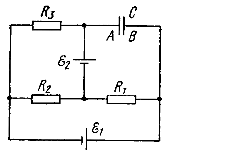 08:07View Solution
In the circuit shown in figure 3.154 find the potential difference `V_(A)-V_(D)`
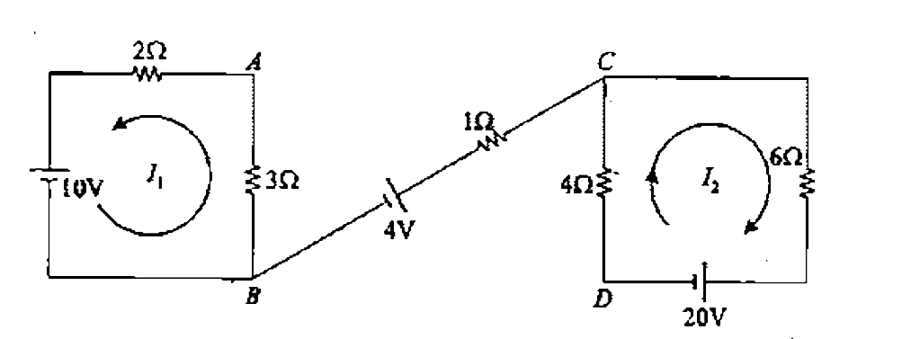 03:57View Solution
In the circuit shown in Fig the sources have `emf's xi_(1) = 1.0 V` and `xi_(2) = 2.5 V` and the resistances have the values `R_(1) = 10 Omega` and `R_(2) = 20 Omega`. The internal resistances of the sources are neglibile . Find a potential differences `varphi_(A) - varphi_(B)` between the plates `A` and `B` of the capacitance `C`.
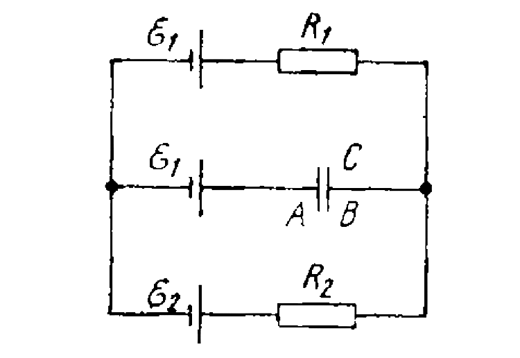 04:06View Solution
In the circuit shown in figure-3.171, find current in `4Omega` resistance.
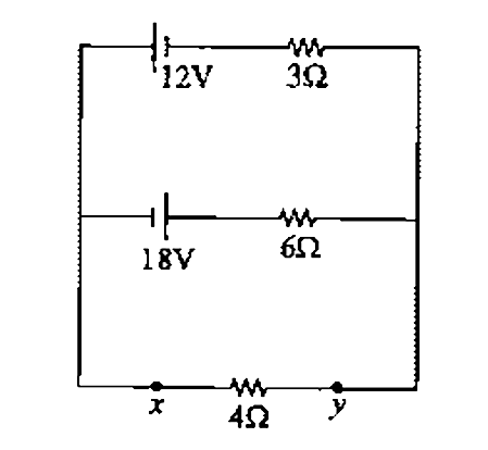 03:29View Solution
Find current in `6Omega` resistance and potential difference across each cell in circuit shown in figure-3.173.
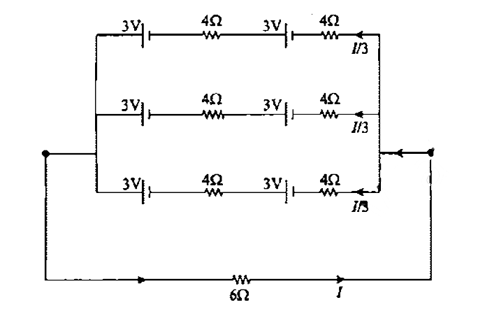 03:57View Solution
In the circuit shown in figure-3.175, find current in `4Omega` resistance by using. Thevenin's Analysis.
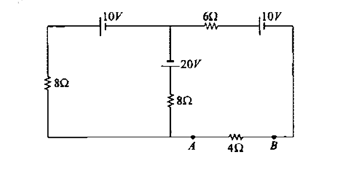 06:42View Solution
In the circuit shown in figure find the heat developed across each resistance in `2 s`.
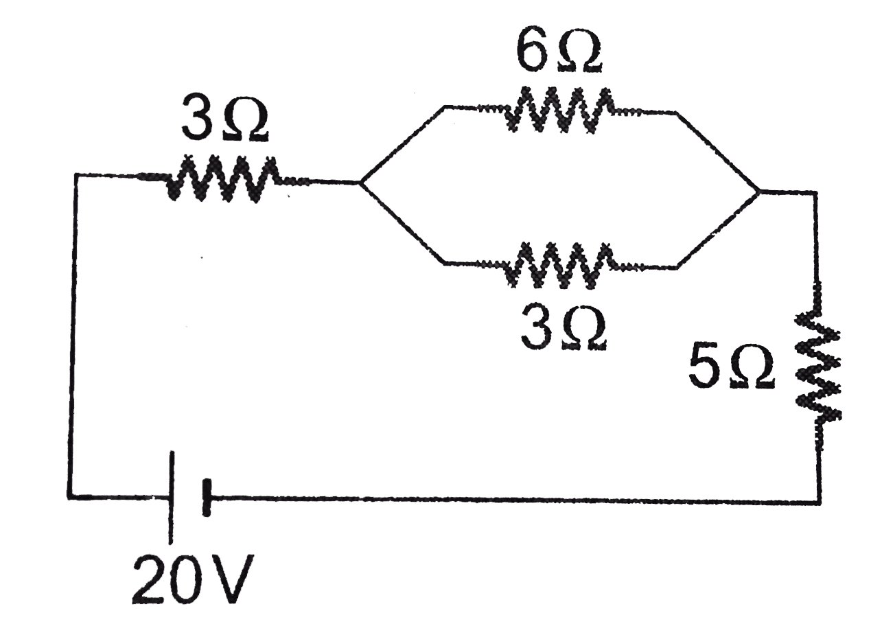 07:37View Solution
Calculate the cost of heating 4.6kg of water for `25^(@)C` to the boiling point, assuming that no energy is wasted. Electrical energy costs 25 paisa per kWh.
04:40View SolutionA battery has an open circuit potential difference of `6V` between its terminals. When a load resistance of `60 Omega` is connected across the battery,the total power supplied by the bttery is `0.4 W`. What should be the load resistance `R`, so that maximum power will be dissipated in `R`. Calculated this power. What is the total power supplied by the battery when such a load is connected?
05:08View SolutionTwo wires of same mass , having ratio of lengths `1 : 2, density 1 : 3`, and specific electrical resistance respectively ` 2 : 1`, are connected one by one to the same volltage supply. The rate of heat dissipation in the first wire is found to be `10 W`. Find the rate of heat dissipation in the second wire.
06:24View SolutionA current passing through a resistance R decreases uniformly to zero in a time internal T and a total charge q passes through resistance. Find the total heat produced in resistance in this process.
06:32View SolutionA bulb is marked 220V, 100W. What will be the current in the filament when connected to 200V?
02:10View SolutionA 500W heater is desigened to operatre at 200V potential differnce. It is connected across 160V line, find the heat it will produce in 20 minute.
03:42View SolutionIn the circuit shown in figure-3.196, find the value of resistance ?R at which the power transferred to this resistance will be maximum.
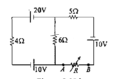 04:54View Solution
A storage battery with emf `2.6 V` loaded with external resistance produces a current `1 A`. In this case, the potential difference between the terminals of the storage battery equals `2 V`. Find the thermal power generated in the battery and the net power supplied by the battery for external circuit.
05:37View SolutionIn the circuit shown in figure-3.198, for what value of R the power dissipated in it will be maximum.
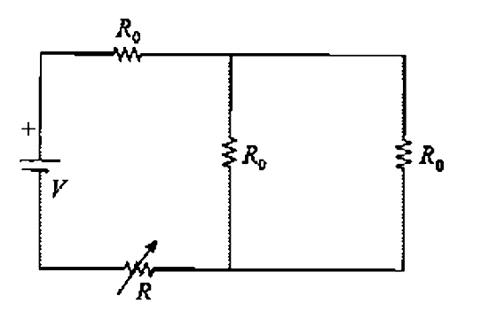 03:42View Solution
The walls of a closed cubical box of edge` 40 cm` are made of a material of thickness `1 mm` and thermal conductivity `4 xx 10^(-4) cals^(-1@) C^(-1)`. The interior of the box is maintained at `100 ^(@) C` above the outside temperature by a heater placed inside the box and connected across `400 V dc` . Calculate the resistance of the heater.
03:50View SolutionThe figure shows part of certain circuit, find,
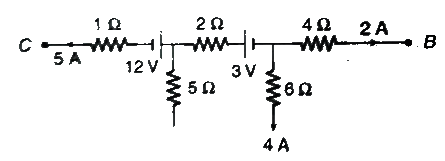
a. power dissipted in `5Omega` resistance,
b.Potential difference `V_C-V_B`
c.Which battery is being charged?03:33View SolutionFind the power supplied or supplied by each batter in the circuit shown in figure -3.201.
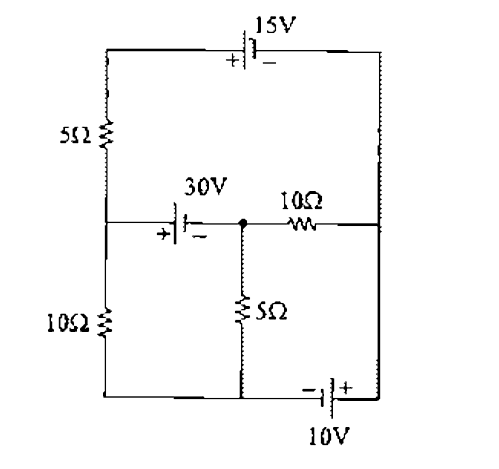 11:47View Solution
Two indentical batteries, each of emf `2V` andinternal resistance `r=1Omega` are connected as shown. The maximum power that can be developed across `R` using these batteries is
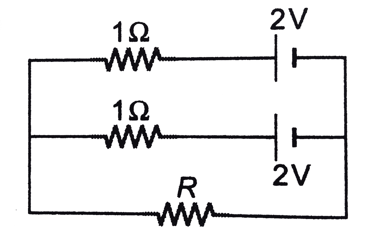 03:47View Solution
In the circuit shown in figure-3.198, for what value of R the power dissipated in it will be maximum.
 03:42View Solution
A capacitor `C` is connected to two equal resistances as shown in the figure. Consider the following statemets
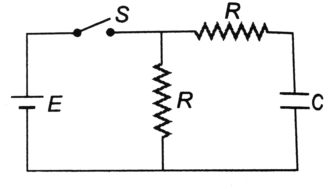
i. At the time of charging of capacitor time constant of the circuit is `2CR`
ii. At the time of discharging of the capacitor the time constant of the circuit is `CR`
iii. At the time of discharging of the capacitor the time constant of the circuit is `2CR`
iv At the time of charging of the capacitor the time constant of the circuit is `2CR`01:39View SolutionFind the charge stored in the capacitor in steady state in the circuit shown below.
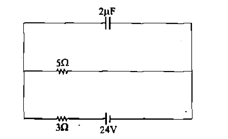 02:08View Solution
Find the charges on `6muF ` and `4muF` capacitors
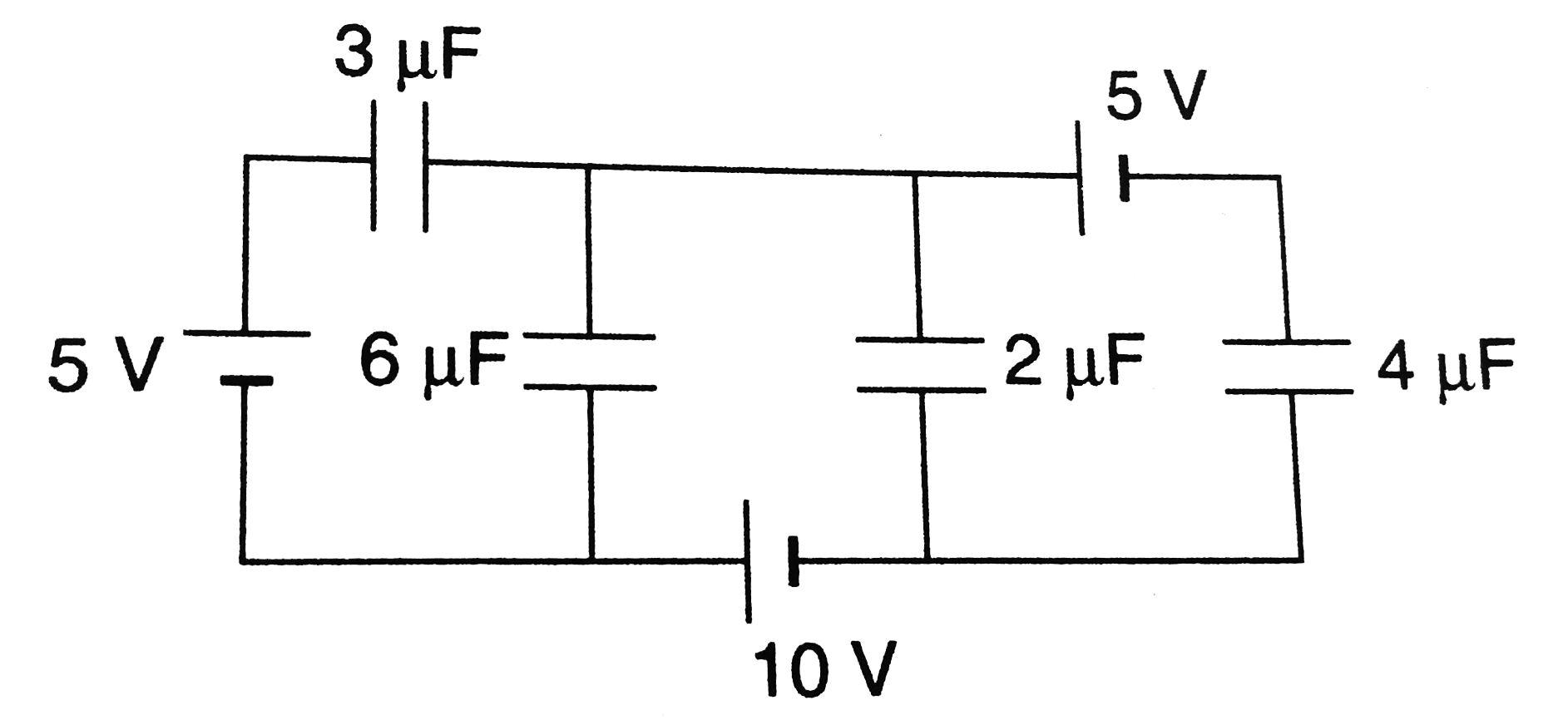 05:29View Solution
In the circuit shown in figure switch `S` is closed at time `t=0`. Find
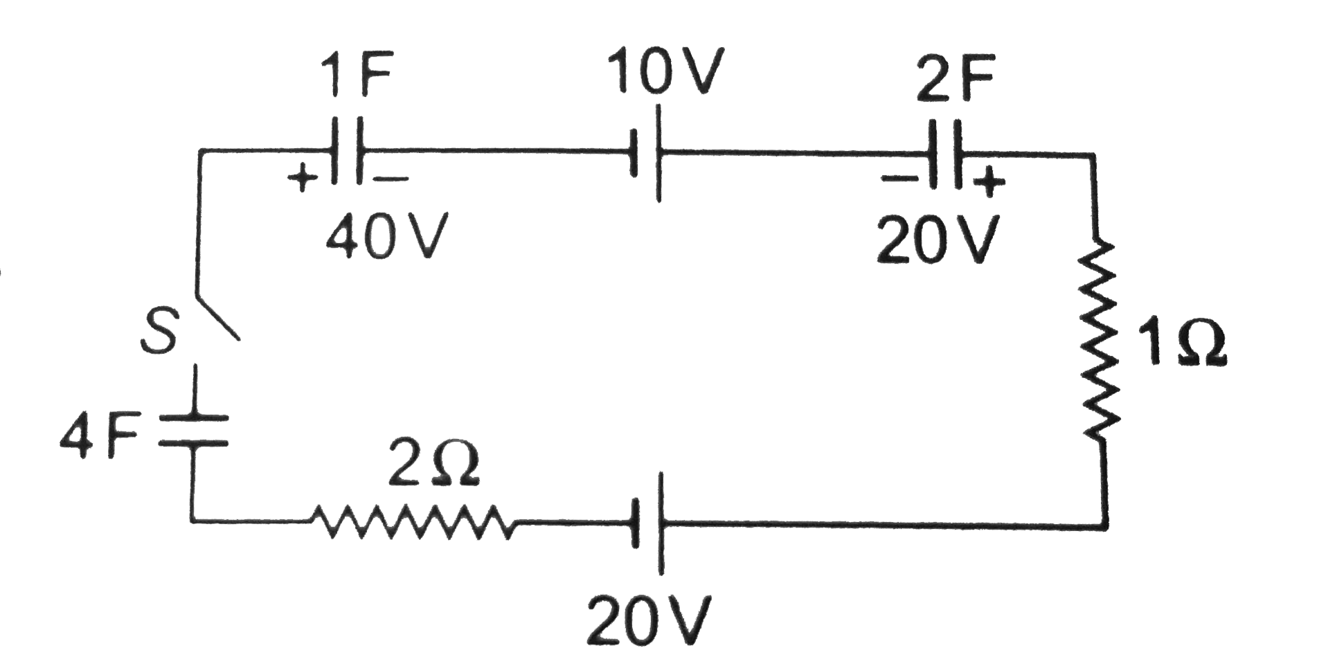
a. Initial current at `t=0` and final current at `t=oo` in the loop.
b. total charge `q` flown from the switch.
c. Final charges on capacitors in steady state at time `t=oo`
d. Loss of energyduring resistribution of charges
e. Individual loss across `1Omega` and `2Omega` resistance.13:19View Solution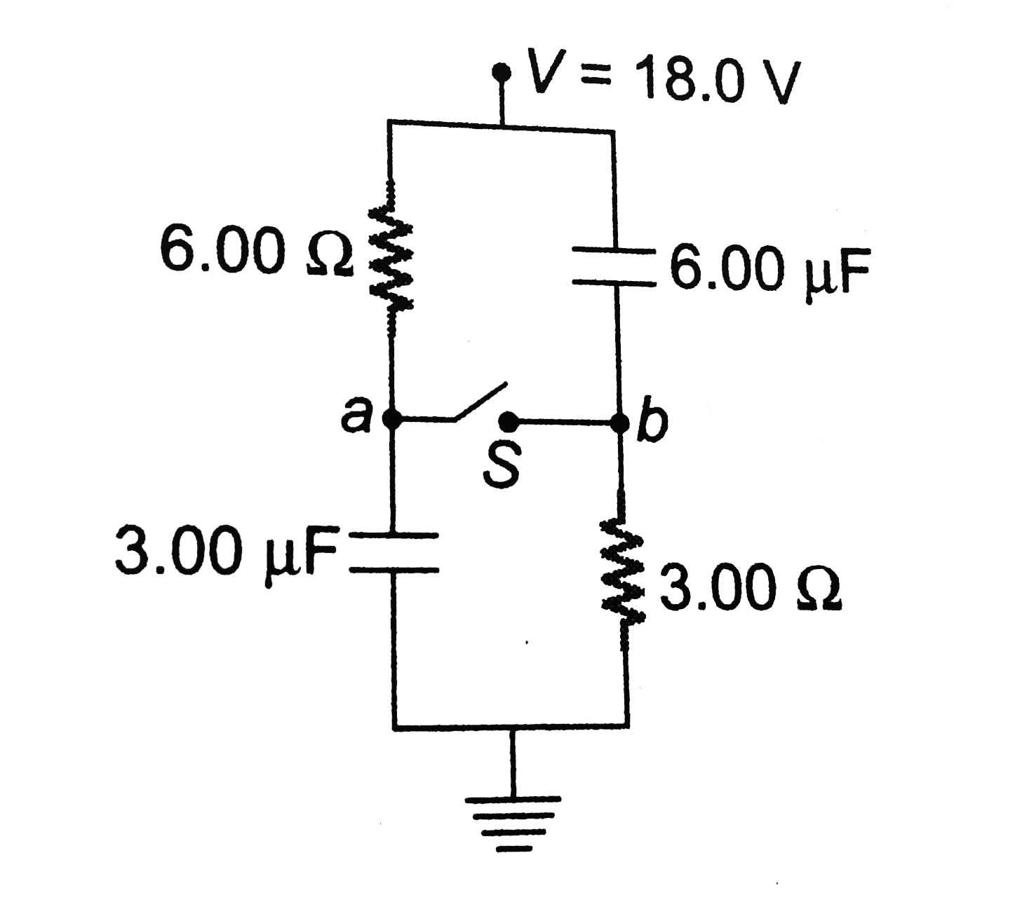
(a) What is the steady state potential of point a with respect to point b in figure when switch `S` is open?
(b) Which point, `a` or `b`, is at the higher potential?
(c) What is the final potential of point `b` with respect to ground when switch `S` is closed?
(d) How much does the charge on each capacitor change when `S` is closed?08:12View SolutionIn the circuit shown in figure-3.238, find the current in `6Omega` resistance just after closing the switch S.
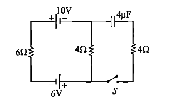 02:40View Solution
In the circuit shown in figure-3.240 switch S is closed at time t=0. find the current through different wires and charge stored on the capacitor at any time t.
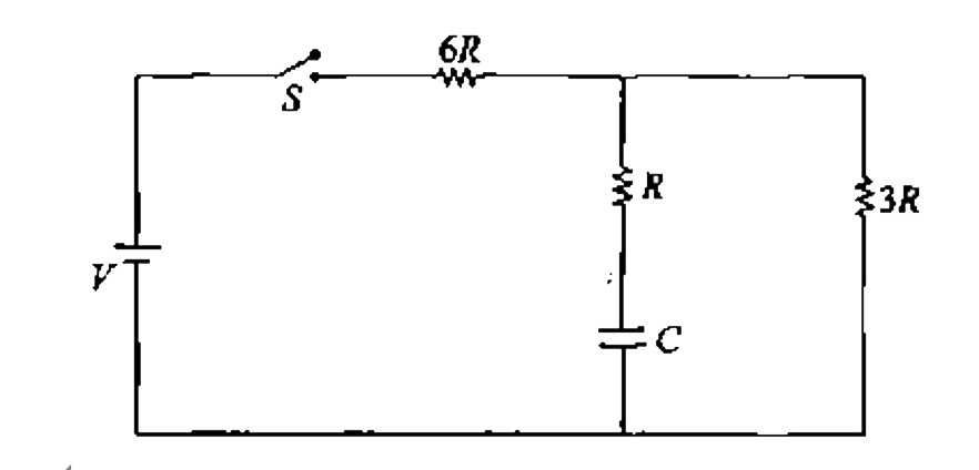 04:06View Solution
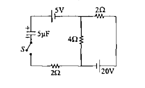
In the circuit shown in figure 3.242 capacitor is charged with `50muC` charge. Find the current in `4Omega` resistance just after switch S is closed.
 05:55View Solution
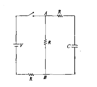
In the circuit shown in figure-3.244, the battery is an ideal one with emf V. The capacitor is initially uncharged. The switch S is closed at time t=0.
(a) Find the charge Q on the capacitor at time l
(b) Find the current in branch AB at time just after closing the switch.
 01:46View Solution
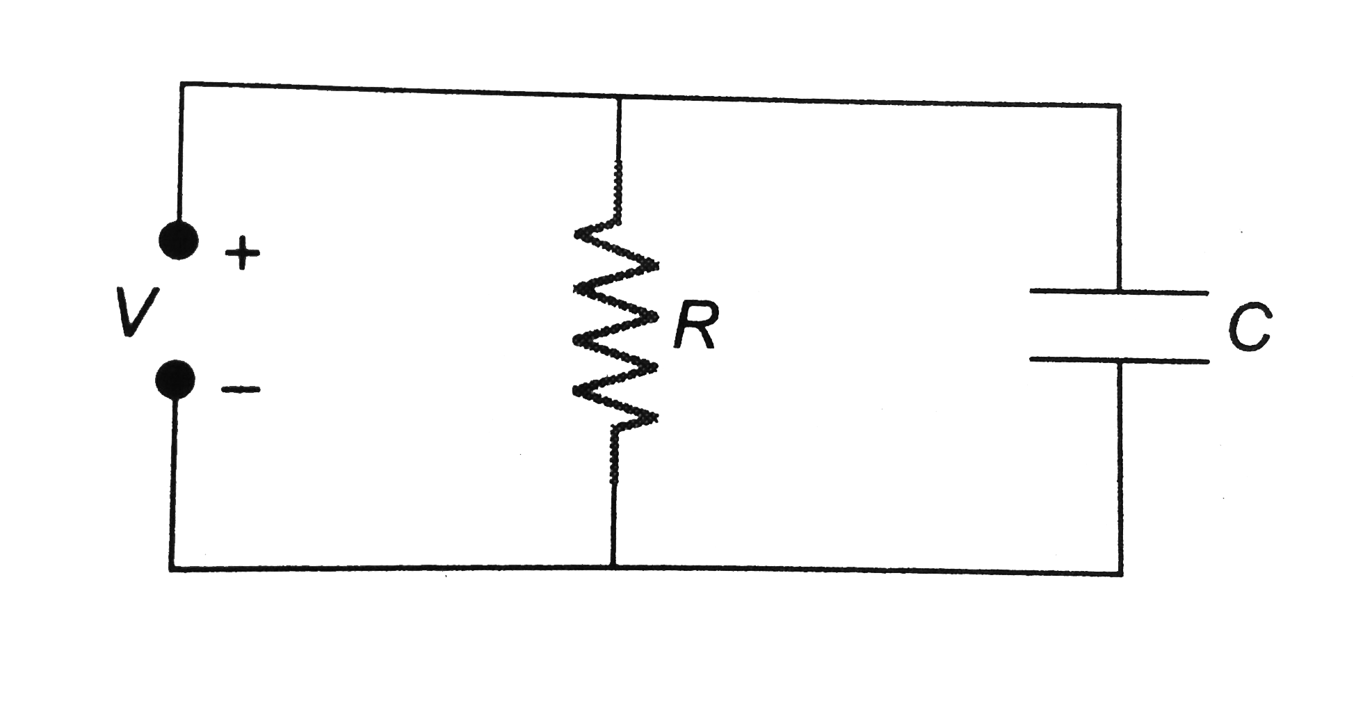
In the circuit shown, a time varying voltage `V = 2000t` volt is applied where `t` is in second. At time `t 5 ms`, determine the Current through the resistor `R= 4 Omega` and through the capacitor `C 300muF`
 02:47View Solution
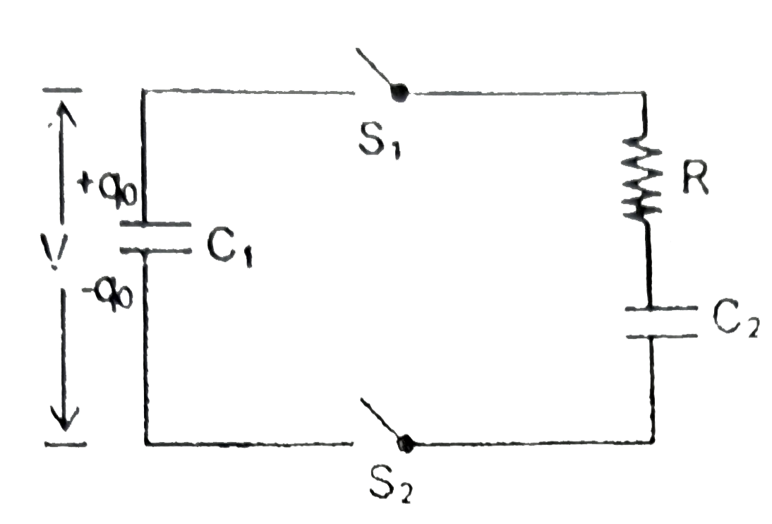
The capacitor `C_(1)` in the figure initially carries a charge `q_(0)`. When the switch `S_(1)` and `S_(2)` are shut, capacitor `C_(1)` is connected in series to a resistor `R` and a second capacitor `C_(2)`, which initially does not carry any charge.
If the heat lost in the resistor after a long time of closing the switch is `(q_(0)^(2)C_(2))/(kC_(1)(C_(1)+C_(2)))`, then Find the value of `k`.
 04:17View Solution
The charge on the capacitor is initially zero. Find the charge on the capacitor as a function of time `t`. All resistors are of equal value `R`.
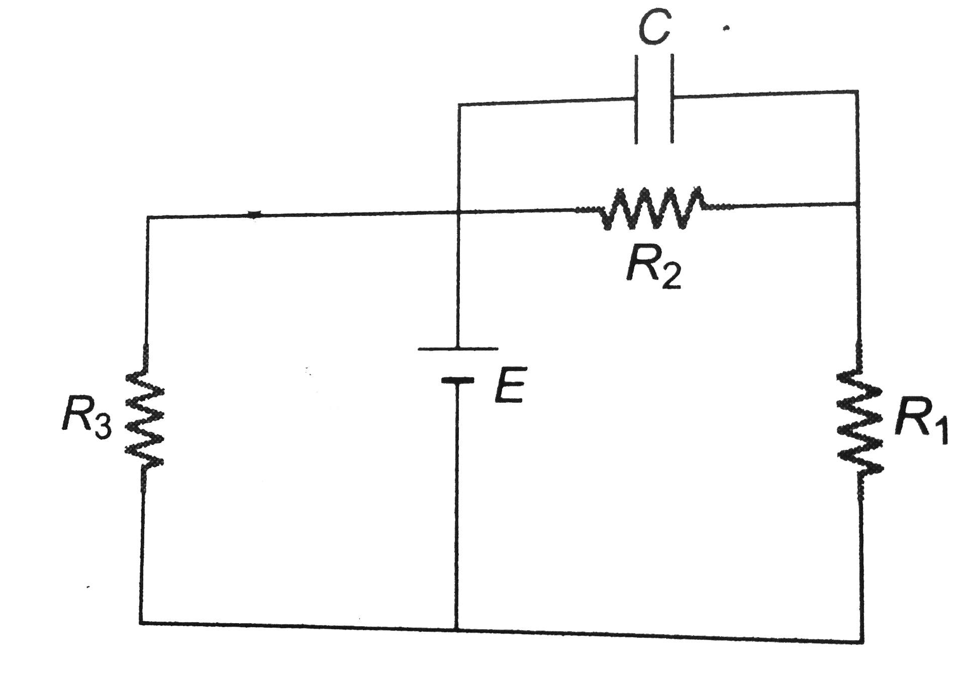 04:37View Solution
The capacitor shown in figure has been charged to a potential difference of `V` volt, so that it carries a charge `CV` with both the switches `S_1 and S_2` remaining open. Switch `S_1` is closed at `t = 0`. At `t= R_1C` switch `S_1` is opened and `S_2` is closed. Find the charge on the capacitor at `t= 2R-1C + R_2C`.
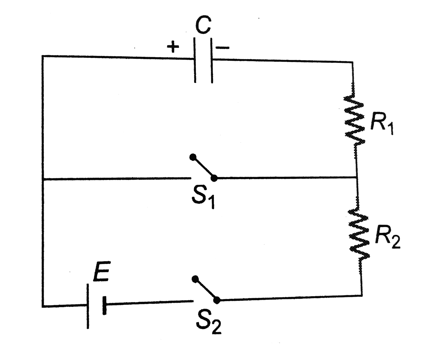 05:20View Solution
What shunt resistance is required to make the `1.00 mA`, `20 Omega` Galvanometer into an ammeter with a range of 0 to `50.0A`?
03:19View SolutionAn electrical circuit is shown in figure. Calculate the potential difference across the resistor of `400 Omega` as will be measured by the voltmeter Vof resistance `400 Omega` either by applying Kirchhoff's rules or otherwise.
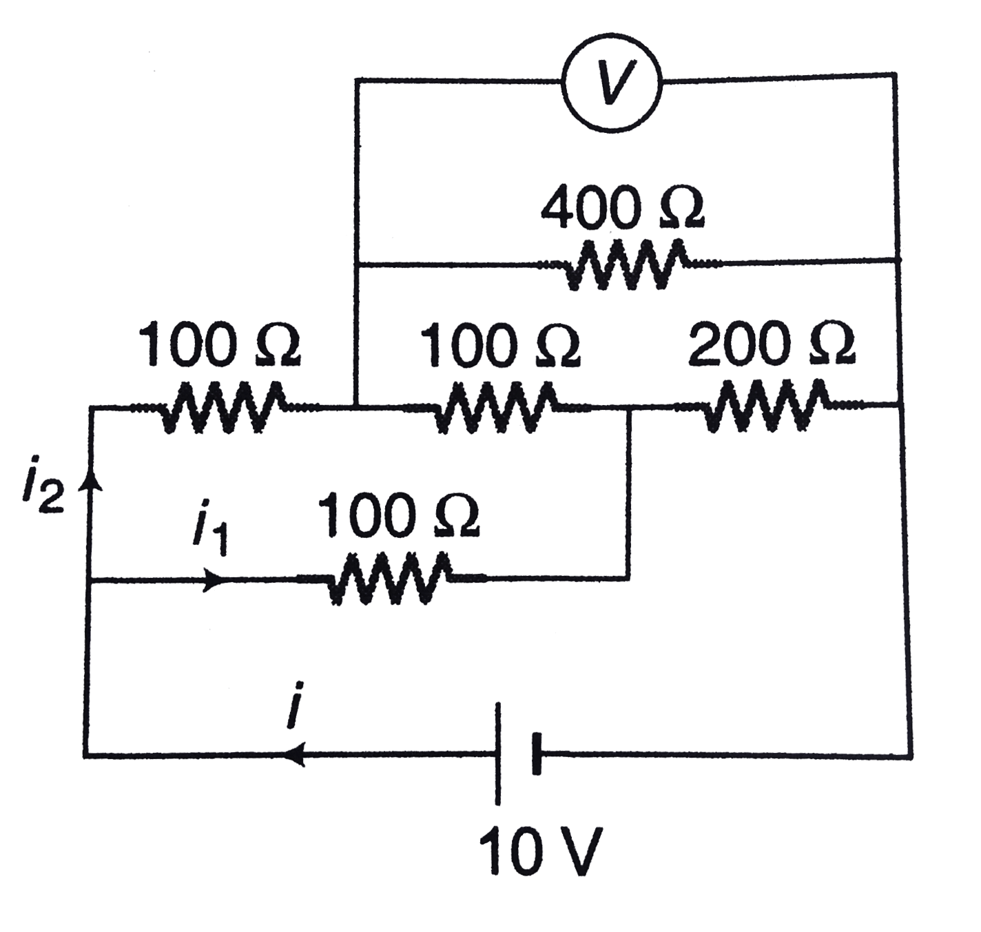 08:27View Solution
An ammeter and a voltmeter are connected in series to a battery with an emf `xi = 6.0 V`. When a certain resistance is connected in parallel with the voltmeter, the readings of the latter decreases `eta = 2.0` times, whereas the readings of the ammeter increase the same number of times, Find the voltmeter readings after the connection of the resistance.
06:47View SolutionA galvanometer with a coil resistance of `100Omega` shows a full-scale deflection when a current of 1 mA is passed through it. What is value of the resistance which can convert this galvanometer into an ammeter showing a full scale deflection for a current 10 A? A resistance of the required value is available but it will get burnt if the energy dissipated in it is greater then 1 W. Can it be used for the conversion of the galvanometer described above?
04:52View SolutionA battery of emf `1.4 V` and internal resistance `2 Omega` is connected to a resistor of `100 omega` resistance through an ammeter. This resistance of the ammeter is `4//3 Omega`. A voltmeter has also been connected to find the potential difference across the resistor.
a. Draw the circuit diagram.
b. The ammeter reads `0.02 A`. What is the resistance of the voltmeter?
c. The voltmeter reads `1.1 V`. What is the error in the reading?09:16View SolutionIn the `R_(1) = 10 Omega ,R_(2) = 20 Omega, R_(3) = 40 Omega R_(4) = 80 Omega` and `V_(A) = 5V,V_(B) = 10V,V_(c) = 20V,V_(D) = 15V` The current in the resistance `R_(1)` will be
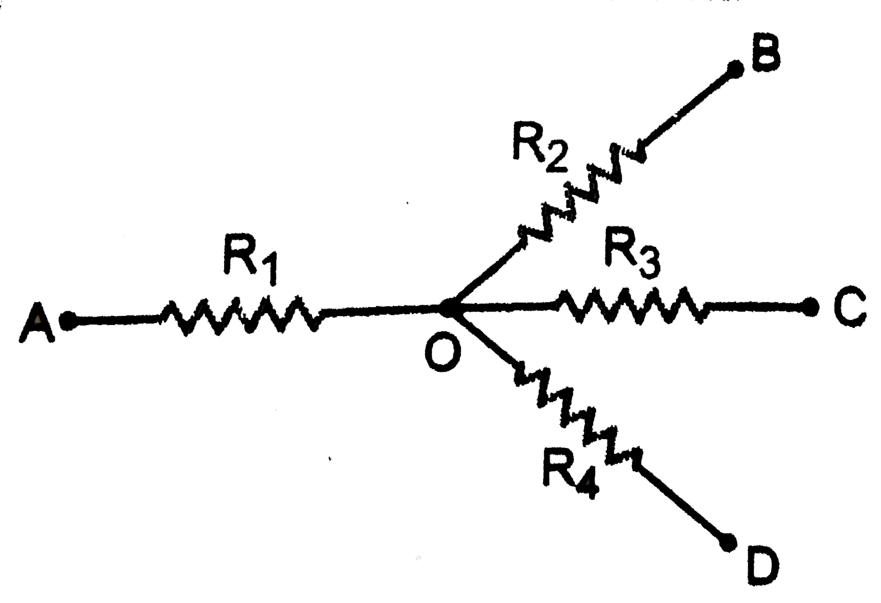 01:33View Solution
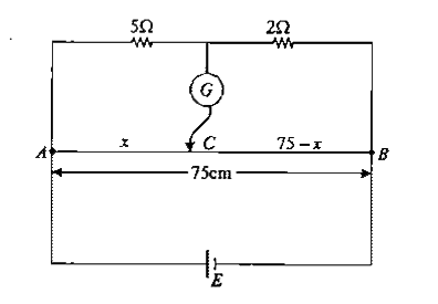
In the meter bridge circuit shown in figure-`3.281` find the length AC at null deflection in galvanometer.
 01:29View Solution
A resistance box, a battery and a galvanometer of resistance `G` ohm are connected in series. the galvanometer is shunted by resistance of `S` ohm, find the change in resistance in the resistance box be required to maintain the current from the battery unchanged.
04:52View SolutionIn the meter bridge circuit shown in figure-`3.281` find the length AC at null deflection in galvanometer.
 01:29View Solution
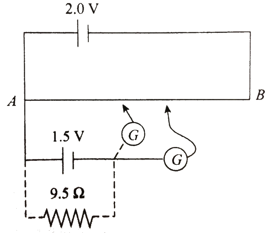
Figure `6.13` shows a `2.0 V` potentiometer used for the determination of internal resistance of a `1.5 V` cell. The balance point of the cell in open circuit is `76.3 cm`. Whan a resistor of `9.5 Omega` is used in the external circuit of the cell, the balance point shifts to `64.8 cm`, length of the potentiometer. Dentermine the internal resistance of the cell.
 02:37View Solution
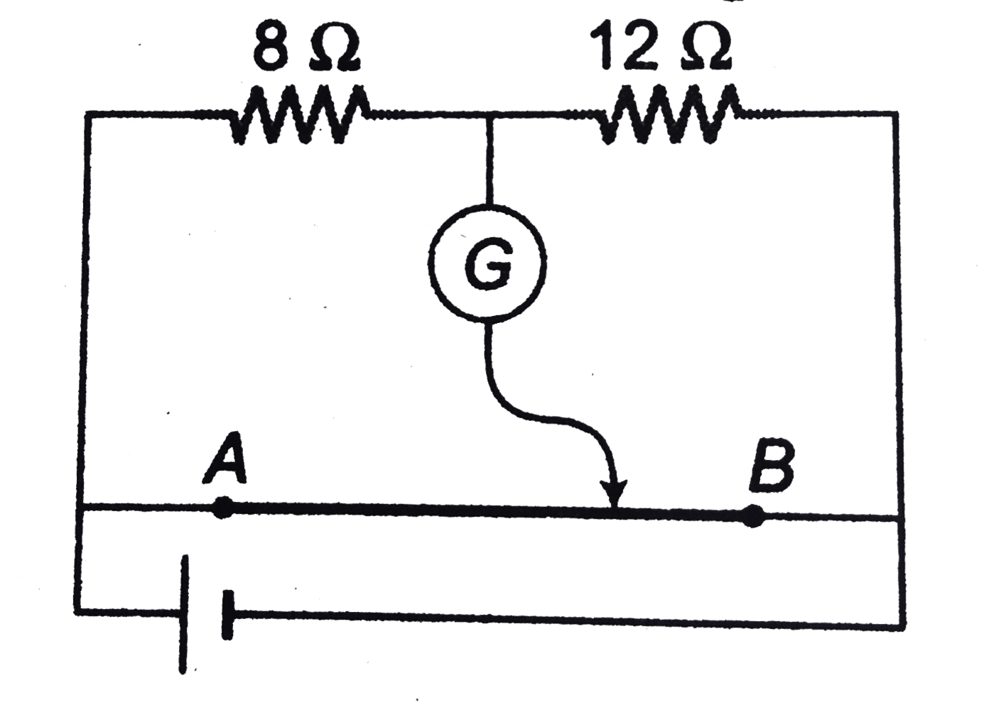
The potentiometer wire `AB` shown in figure is `40 cm` long. Where the free end of the galvanometer should be connected on `AB` so that the galvanometer may show zero deflection?
 02:13View Solution
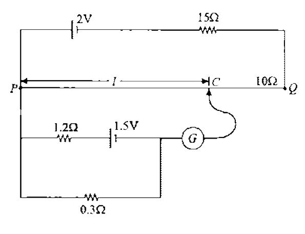
Figure-`3.287` shows a potentiometer with length of wire Im and resistance `10 Omega` . In this system find length PC when galvanometer shows null deflection.
 05:37View Solution
A potentiometer wire of length `100 cm` having a resistance of `10 Omega` is connected in series with a resistance `R` and a cell of emf `2V` of negligible internal resistance. A source of emf
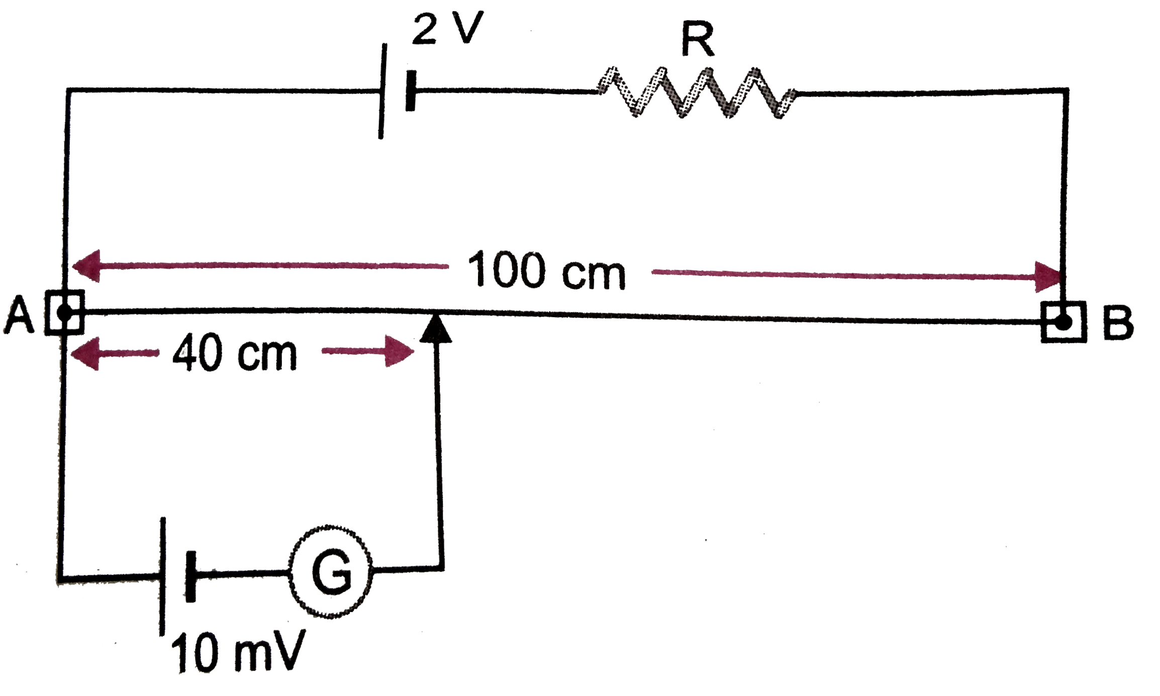
of `10 mV` is balanced against a length of `40 cm` of the potentiometer wire. What is the value of resistance `R` ?04:56View SolutionFigure-`3.287` shows a potentiometer with length of wire Im and resistance `10 Omega` . In this system find length PC when galvanometer shows null deflection.
 05:37View Solution
The potentiometer wire `AB` is `600` cm long.
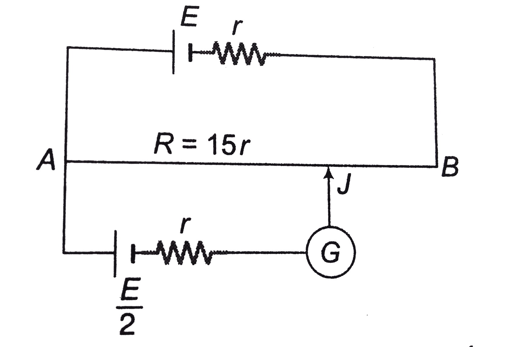 a. At what distance from A should be jockey `J` touch the wire to get zero deflection i the galvanometer.
b. If the jockey touches the wire at a distance `560 cm` from A, what will be the current through the galvanometer.03:36View SolutionA voltmeter of resistance `R_1` and an ammeter of resistance `R_2` are connected in series across a battery oif negligible internal resistance. When as resistance `R` is connected in parallel to voltmeter reading of ammeter increases three times white that of voltmeter reduces to one third. Find `R_1` and `R_2` in terms of `R`.
06:57View SolutionA straight copper-wire of length 100m and cross-sectional area 1.0`mm^(2)` carries a current 4.5A. Assuming that one free electron corresponds to each copper atom, find
(a) The time it takes an electron to displace from one end of the wire to the other.
(b) The sum of electroc forces acting on all free electrons in the given wire. given resistivity of copper is `1.72xx10^(-8)Omega-m` and density of copper is `8.96g//cm^(3)`.14:16View Solution
All Questions questions and complete solutions for chapter CURRENT ELECTRICITY of GK PUBLICATIONS PHYSICS (HINGLISH) of Class 12
