Complete Solutions to EXERCISE of chapter ALTERNATING CURRENT of Class 12 book with complete answers and questions
| Class 12 | PHYSICS |
| Chapter | ALTERNATING CURRENT |
| PSEB | EXERCISE |
| Number Of Questions | 49 |
| Academic Year | 2023-24 |
A `100 Omega` resistor is connected to a 220 V, 50 Hz ac supply. What is the rms value of current in the circuit?
View SolutionA `100 Omega`resistor is connected to a 220 V, 50 Hz ac supply. What is the net power consumed over a full cycle?
View SolutionThe peak voltage of an ac supply is 300 V. What is the rms voltage?
View SolutionThe peak voltage of an ac supply is 300 V. The rms value of current in an ac circuit is 10 A. What is the peak current?
View SolutionA 44 mH inductor is connected to 220 V, 50 Hz ac supply. Determine the rms value of the current in the circuit.
View SolutionA `60 muF` capacitor is connected to a 110 V, 60 Hz ac supply. Determine the rms value of the current in the circuit.
View Solution(A) A 44 mH inductor is connected to 220 V, 50 Hz ac supply. (B) A 60 microF capacitor is connected to 110 V, 60 Hz ac supply. What is the net power absorbed by each circuit (A) and (B) over a complete cycle. Explain your answer.
View SolutionObtain the resonant frequency or of `omega_r` series LCR circuit with L = 2.OH, `C = 32 muF` and `R= 10 Omega` . What is the Q-value of this circuit?
View SolutionA charged `30 muF` capacitor is connected to a 27 mH inductor. What is the angular frequency of free oscillations of the circuit?
View SolutionA charged 30 micro Farad capacitor is connected to a 20 mH inductor. Suppose the initial charge on the capacitor is 6 mC. What is the total energy stored in the circuit initially? What is the total energy at later time?
View SolutionA series LCR circuit with `R= 20 Omega` ,L=1.5H and `C = 35 muF` is connected to a variable-frequency 200 V ac supply. When the frequency of the supply equals the natural frequency of the circuit, what is the average power transferred to the circuit in one complete cycle?
View SolutionA radio can tune over the frequency range of a portion of MW broadcast band: (800 kHz to 1200 kHz). If its LC circuit has an effective inductance of `200 muH`, what must be the range of its variable capacitor?
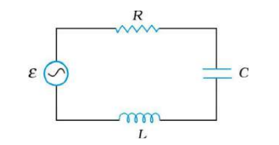
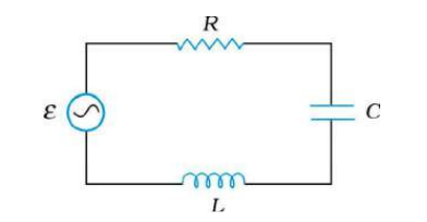
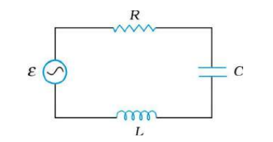
View SolutionFigure 7.21 shows a series LCR circuit connected to a variable frequency 230 V source. L = 5.0 H, `C = 80 muF`, `R= 40 Omega` . Determine the source frequency which drives the circuit in resonance. :

View SolutionFigure shows a series LCR circuit connected to a variable frequency 230 V source. L = 5.0 H, `C = 80 muF`, `R= 40 Omega` . Obtain the impedance of the circuit and the amplitude of current at the resonating frequency. :

View SolutionFigure shows a series LCR circuit connected to a variable frequency 230 V source. L = 5.0 H, `C = 80 muF`, `R= 40 Omega`. Determine the rms potential drops across the three elements of the circuit. Show that the potential drop across the LC combination is zero at the resonating frequency. :

View SolutionAn LC circuit contains a 20 mH inductor and a `50 muF` capacitor with an initial charge of 10 mC. The resistance of the circuit is negligible. Let the instant the circuit is closed be t = 0. What is the total energy stored initially? Is it conserved during LC oscillations?
View SolutionAn LC circuit contains a 20 mH inductor and a `50 muF` capacitor with an initial charge of 10 mC. The resistance of the circuit is negligible. Let the instant the circuit is closed be t = 0. What is the total energy stored initially? What is the natural frequency of the circuit?
View SolutionAn LC circuit contains a 20 mH inductor and a `50 muF` capacitor with an initial charge of 10 mC. The resistance of the circuit is negligible. Let the instant the circuit is closed be t = 0. At what time is the energy stored completely electrical (i.e., stored in the capacitor)?
View SolutionAn LC circuit contains a 20 mH inductor and a `50 muF` capacitor with an initial charge of 10 mC. The resistance of the circuit is negligible. Let the instant the circuit is closed be t = 0. At what time is the energy stored completely magnetic (i.e., stored in the inductor)?
View SolutionAn LC circuit contains a 20 mH inductor and a `50 muF` capacitor with an initial charge of 10 mC. The resistance of the circuit is negligible. Let the instant the circuit is closed be t = 0. At what times is the total energy shared equally between the inductor and the capacitor?
View SolutionAn LC circuit contains a 20 mH inductor and a `50 muF` capacitor with an initial charge of 10 mC. The resistance of the circuit is negligible. Let the instant the circuit is closed be t = 0. If a resistor is inserted in the circuit, how much energy is eventually dissipated as heat?
View SolutionA coil of inductance 0.50 H and resistance `100 Omega` is connected to a 240 V, 50 Hz ac supply. What is the maximum current in the coil?
View SolutionA coil of inductance 0.50 H and resistance `100 Omega` is connected to a 240 V, 50 Hz ac supply. What is the time lag between the voltage maximum and thecurrent maximum?
View SolutionA coil of inductance 0.50 H and resistance 100 ohm is connected to a high frequency supply (240 V, 10 kHz). (a) Obtain the maximum current in the coil. (b) what is the time lag between voltage maximum and the current maximum. Hence, explain the statement that at very high frequency, an inductor in a circuit nearly amounts to an open circuit. How does an inductor behave in a dc circuit after the steady state?
View SolutionA `100 muF` capacitor in series with a `40 Omega` resistance is connected to a 110 V, 60 Hz supply. What is the maximum current in the circuit?
View SolutionA `100 muF` capacitor in series with a `40 Omega` resistance is connected to a 110 V, 60 Hz supply. What is the time lag between the current maximum and the voltage maximum?
View SolutionA 100 micro F capacitor in series with a 40 ohm resistance is connected to a 110 V, 12 kHz supply? (a) What is the maximum current in the circuit? (b) What is time lag between the current maximum and voltage maximum? Hence, explain the statement that a capacitor is a conductor at very high frequencies. Compare this behaviour with that of a capacitor in a dc circuit after the steady state.
View SolutionLCR circuit connected to a variable frequency 230 V source . L=5.0 H, C=80 micro F and R=40 ohm. Keeping the source frequency equal to the resonating frequency of the series LCR circuit, if the three elements, L, C and R are arranged in parallel, show that the total current in the parallel LCR circuit is minimum at this frequency. Obtain the current rms value in each branch of the circuit for the elements and source.
View SolutionA circuit containing a 80 mH inductor and a `60 muF` capacitor in series is connected to a 230 V, 50 Hz supply. The resistance of the circuit is negligible. Obtain the current amplitude and rms values.
View SolutionA circuit containing a 80 mH inductor and a `60 muF` capacitor in series is connected to a 230 V, 50 Hz supply. The resistance of the circuit is negligible. Obtain the rms values of potential drops across each element.
View SolutionA circuit containing a 80 mH inductor and a `60 muF` capacitor in series is connected to a 230 V, 50 Hz supply. The resistance of the circuit is negligible. What is the average power transferred to the inductor?
View SolutionA circuit containing a 80 mH inductor and a `60 muF` capacitor in series is connected to a 230 V, 50 Hz supply. The resistance of the circuit is negligible. What is the average power transferred to the capacitor?
View SolutionA circuit containing a 80 mH inductor and a `60 muF` capacitor in series is connected to a 230 V, 50 Hz supply. The resistance of the circuit is negligible. What is the total average power absorbed by the circuit? [‘Average’ implies ‘averaged over one cycle’.]
View SolutionA circuit containing a 80 mH inductor and a `60 micro F` capacitor in series and has a resistance of `15 Omega` is connected to a 230 V, 50 Hz supply Obtain the average power transferred to each element of the circuit, and the total power absorbed.
View SolutionA series LCR circuit with L=0.12H, C = 480 nF, `R= 23 Omega` is connected to a 230 V variable frequency supply. What is the source frequency for which current amplitude is maximum. Obtain this maximum value.
View SolutionA series LCR circuit with L=0.12H, C = 480 nF, `R= 23 Omega` is connected to a 230 V variable frequency supply. What is the source frequency for which average power absorbed by the circuit is maximum. Obtain the value of this maximum power.
View SolutionA series LCR circuit with L=0.12H, C = 480 nF, `R= 23 Omega` is connected to a 230 V variable frequency supply. For which frequencies of the source is the power transferred to the circuit half the power at resonant frequency? What is the current amplitude at these frequencies?
View SolutionA series LCR circuit with L=0.12H, C = 480 nF, `R= 23 Omega` is connected to a 230 V variable frequency supply. What is the Q-factor of the given circuit?
View SolutionObtain the resonant frequency and Q-factor of a series LCR circuit ith L = 3.0 H, `C = 27 muF`, and `R = 7.4 Omega`. It is desired to improve the sharpness of the resonance of the circuit by reducing its ‘full width at half maximum’ by a factor of 2. Suggest a suitable way.
View SolutionAnswer the following questions: In any ac circuit, is the applied instantaneous voltage equal to the algebraic sum of the instantaneous voltages across the series elements of the circuit? Is the same true for rms voltage?
View SolutionAnswer the following questions: A capacitor is used in the primary circuit of an induction coil.
View SolutionAnswer the following questions: An applied voltage signal consists of a superposition of a dc voltage and an ac voltage of high frequency. The circuit consists of an inductor and a capacitor in series. Show that the dc signal will appear across C and the ac signal across L.
View SolutionAnswer the following questions: A choke coil in series with a lamp is connected to a dc line. The lamp is seen to shine brightly. Insertion of an iron core in the choke causes no change in the lamp’s brightness. Predict the corresponding observations if the connection is to an ac line.
View SolutionAnswer the following questions: Why is choke coil needed in the use of fluorescent tubes with ac mains? Why can we not use an ordinary resistor instead of the choke coil?
View SolutionA power transmission line feeds input power at 2300 V to a stepdown transformer with its primary windings having 4000 turns. What should be the number of turns in the secondary in order to get output power at 230 V?
View SolutionAt a hydroelectric power plant, the water pressure head is at a height of 300 m and the water flow available is `100 m^3s^-1`. If the turbine generator efficiency is 60%, estimate the electric power available from the plant `(g = 9.8 ms^-2)`.
View SolutionA small town with a demand of 800 kW of electric power at 220 V is situated 15 km away from an electric plant generating power at 440 V. The resistance of the two wire line carrying power is `0.5 Omega` per km. The town gets power from the line through a 4000-220 V step-down transformer at a sub-station in the town. Estimate the line power loss in the form of heat.
View SolutionA small town with a demand of 800 kW of electric power at 220 V is situated 15 km away from an electric plant generating power at 440 V. The resistance of the two wire line carrying power is `0.5 Omega` per km. The town gets power from the line through a 4000-220 V step-down transformer at a sub-station in the town. Flow much power must the plant supply, assuming there is negligible power loss due to leakage?
View SolutionA small town with a demand of 800 kW of electric power at 220 V is situated 15 km away from an electric plant generating power at 440 V. The resistance of the two wire line carrying power is `0.5 Omega` per km. The town gets power from the line through a 4000-220 V step-down transformer at a sub-station in the town. Characterise the step up transformer at the plant.
View Solution
EXERCISE questions and complete solutions for chapter ALTERNATING CURRENT of PSEB of Class 12