Comprehension from DC PANDEY PHYSICS Chapter 11 ELECTROSTATICS for Class 11
| Class 11 | PHYSICS |
| Chapter | ELECTROSTATICS |
| DC PANDEY PHYSICS | Comprehension |
| Medium | English |
| Academic Year | 2023-2024 |
Question 9
Electric potential is a scalar quantity. Due to a point charge charge q at distance r, the potential is given by V=q4π∈0r. A point charge q is placed at (3a,0) and another charge −2q is placed at (−3a,0).
At how many points on the x-axis, (at finite distance) electric potential will be zero?View SolutionQuestion 13
When two concentric shells are connected by a thin conducting wire, whole of the charge of inner shell transfers to the outer shell and potential difference between them becomes zero. Surface charge densities of two thin concentric spherical shells are σ and −σ respectively. Their radii are R and 2R. Now they are connected by a thin wire.
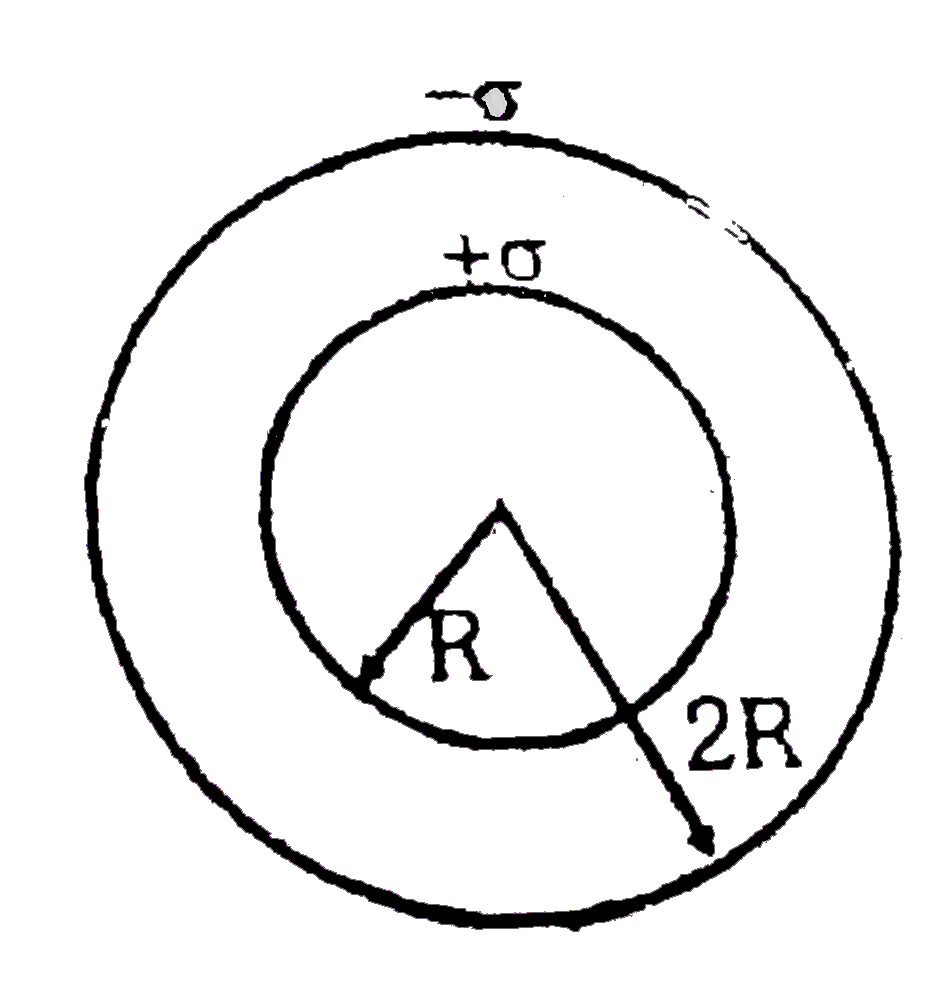
Potential on either of the shells will be :-View SolutionQuestion 14
When two concentric shells are connected by a thin conducting wire, whole of the charge of inner shell transfers to the outer shell and potential difference between them becomes zero. Surface charge densities of two thin concentric spherical shells are σ and −σ respectively. Their radii are R and 2R. Now they are connected by a thin wire.
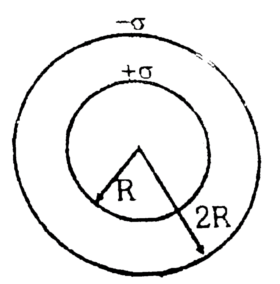
Suppose electric field at a distance r(>2R) was E1 before connecting the two shells and E2 after connecting the two shells, then ∣∣∣E2E1∣∣∣ is :-View SolutionQuestion 15
In C−R circuit, answer the following two questions
During charging of C−R circuit let t1 and t2 be the time constant and initial charging current when capacitor is assumed to be filled by a perfect insulator and t2 and i2 be the corresponding values when it is assumed imperfect. ThenView SolutionQuestion 17
In the figure mA=mB=1kg. Block A is neutral while qB=−1C. Sizes of A and B are negligible. B is released from rest at a distance 1.8 m fromt A. Initially spring is neither compressed nor elongated.

If collision between A and B is perfectly inelastic, what is velocity of combined mass just after collision ?View SolutionQuestion 22
A solid conducting sphere of radius 'a' is surrounded by a thin uncharged concentric conducting shell of radius 2a. A point charge q is placed at a distance 4a from common centre of conducting sphere and shell. The inner sphere is then grounded

The potential of outer shell isView SolutionQuestion 24
Capacitor C3 in the circuit is a veriable capacitor (its capacitance can be varied). Group is plotted between potential difference V1 (across capacitor C1) versus C3. Electric potential V1 approaches to 10 V as C3→∞. Given that C1+C2=10μF

The capacitance of the capacitor C1 value View SolutionQuestion 25
Capacitor C3 in the circuit is variable capacitor (its capacitance can be varied). Graph is plotted between potential difference V1 (across capacitor C1) versus C3.
Electric potential V1 approaches on asymptote of 10 volts as C3→∞
The value of C3 for which potential difference across C1 will become 8V, is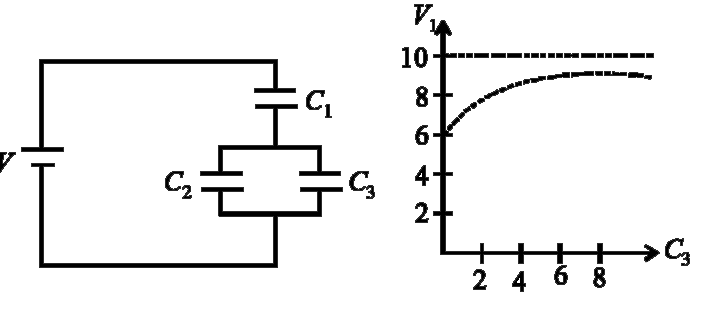 View Solution
Question 28
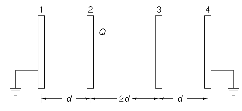
Four large identical metallic plates are placed as shown in the Figure. Plate 2 is given a charge Q. All other plates are neutral. Now plates 1 and 4 are earthed. Area of each plate is A.
(a) Find charge appearing on right side of plate 3.
(b) Find potential difference between plates 1 and 2.
 View Solution
Question 34
Four large metallic plates of area A each are kept parallel to each other with a small separation between them as shown in the figure. A cell of emf V is connected across the two outermost plates through a switch K1. The two inner plates are similarly connected with a cell of emf 2 V through a switch k2 Initially both switched are open and the plates, starting form left to right (i.e. number 1 to 4) are given charges Q,2Q,−2Q and −Q respectively. Now answer the following questions

The charge appearing on the outer surface of plate -1, when switches K1,K2 are open View SolutionQuestion 35
Four large metallic plates of area A each are kept parallel to each other with a small separation between them as shown in the figure. A cell of emf V is connected across the two outermost plates through a switch K1. The two inner plates are similarly connected with a cell of emf 2 V through a switch k2 Initially both switched are open and the plates, starting form left to right (i.e. number 1 to 4) are given charges Q,2Q,−2Q and −Q respectively. Now answer the following questions

If K1 is closed and K2 is open the charge appearing on the right surface of plate-2 isView SolutionQuestion 36
Four large metallic plates of area A each are kept parallel to each other with a small separation between them as shown in the figure. A cell of emf V is connected across the two outermost plates through a switch K1. The two inner plates are similarly connected with a cell of emf 2 V through a switch k2 Initially both switched are open and the plates, starting form left to right (i.e. number 1 to 4) are given charges Q,2Q,−2Q and −Q respectively. Now answer the following questions

If both switches are closed, the charge appearing on the plate 4 isView Solution


