Exercise 23.8 from DC PANDEY PHYSICS (HINGLISH) CURRENT ELECTRICITY for Class 12
| Class 12 | PHYSICS |
| Chapter | CURRENT ELECTRICITY |
| DC PANDEY PHYSICS (HINGLISH) | Exercise 23.8 |
| Medium | English |
| Academic Year | 2023-2024 |
Question 21
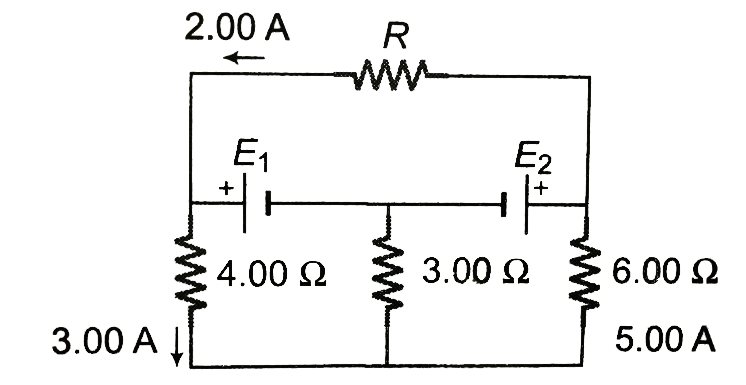
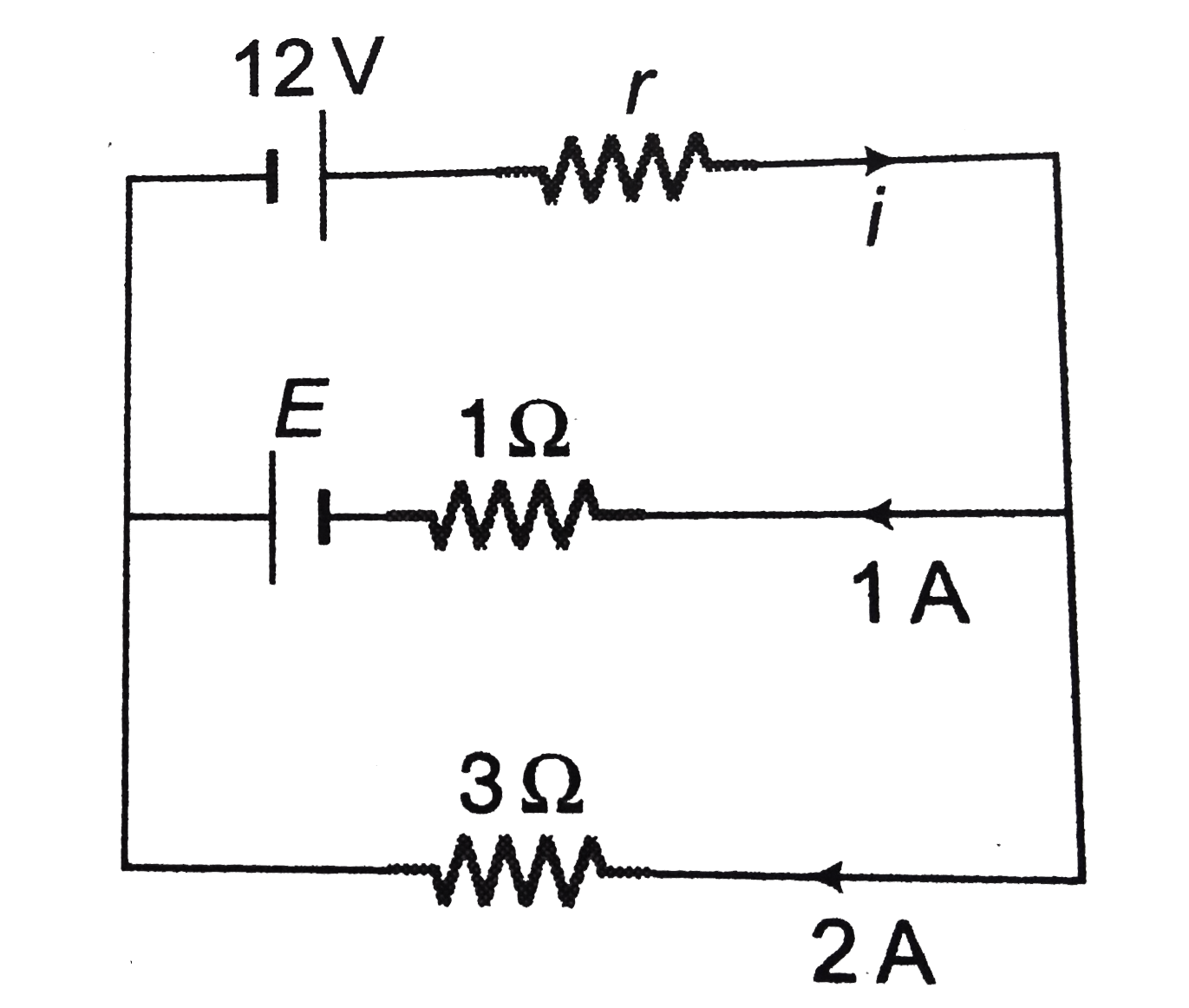
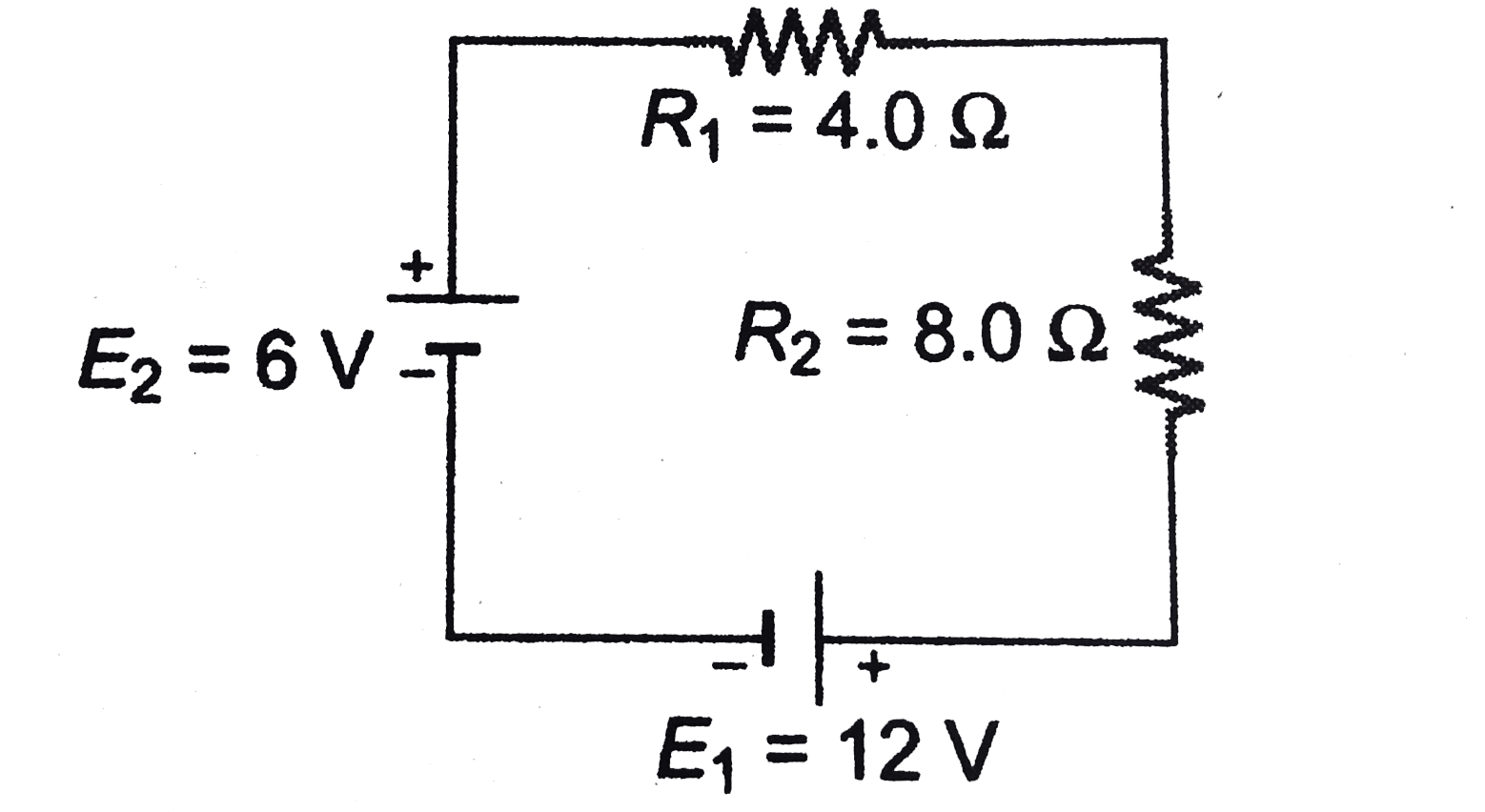
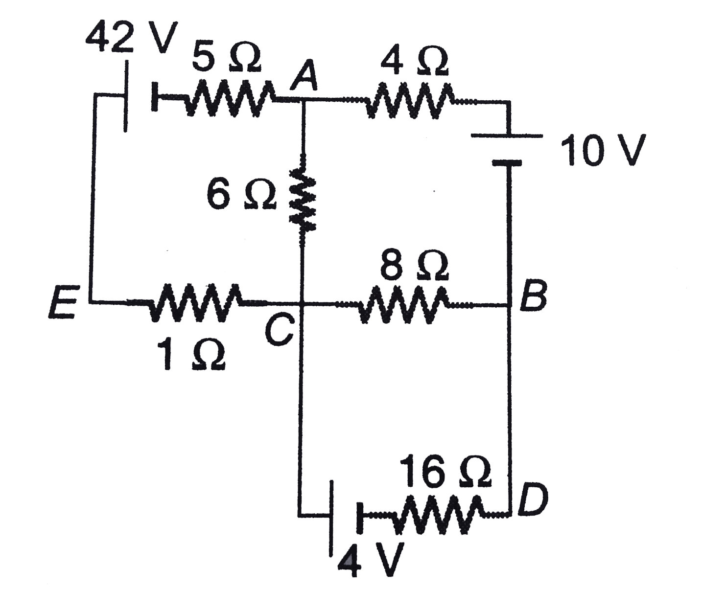
In the circuit shown in figure a 12V battery with unknown internal resistance r is connected to another battery with unknown emf E and internal resistance 1Ω and to a resistance of 3Ω carrying a current of 2A. The current through the rechargeable battery is 1A in the direction shown. Figure the unknown current i internal resistance r and the emf E.
 View Solution
Question 28
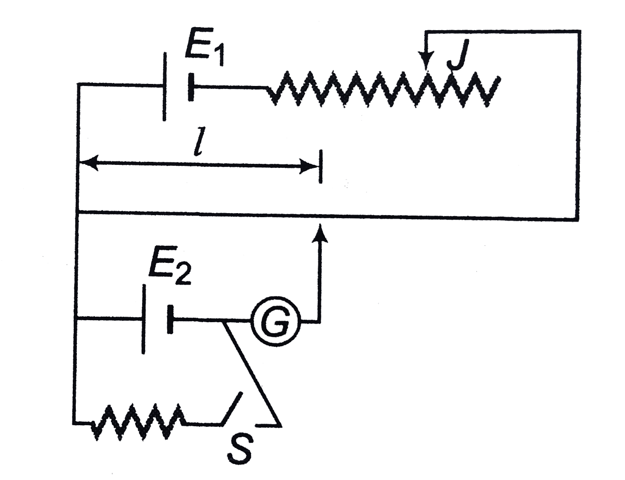
In a potentiometer experiment it is found that no current passes through the galvanometer when the terminals of the cell are connected across 0.52m of the potentiometer wire. If the cell is shunted by a resistance of 5Ω balance is obtained when the cell connected across0.4m of the wire. Find the internal resistance of the cell.View SolutionQuestion 30
A resistance of 2Ω is connected across one gap of a meter bridge (the length of the wire is 100cm) and an unknown resistance, greater than 2Ωis conneted across the other gap. When these resistances are interchanged, the balance point shifts by 20cm. Neglecting any corrections, the unknown resistance is View SolutionQuestion 31
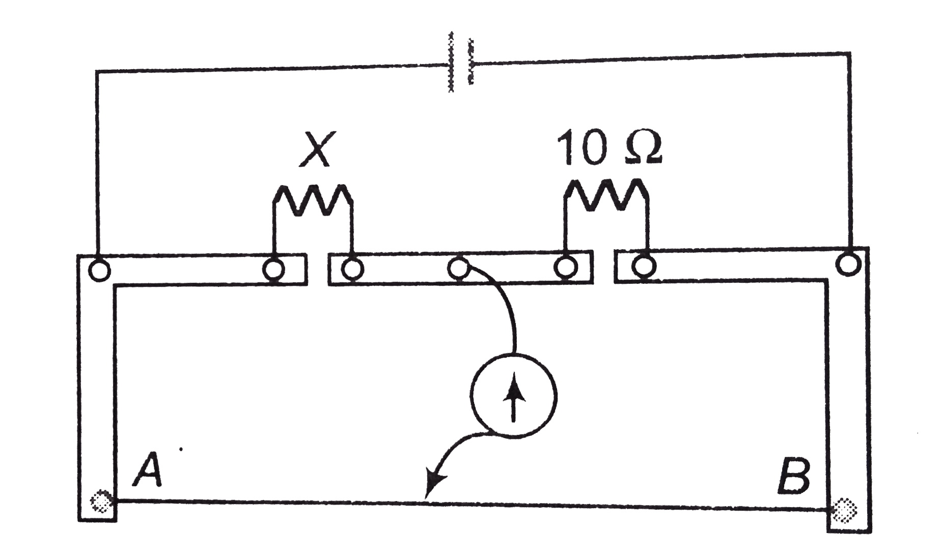
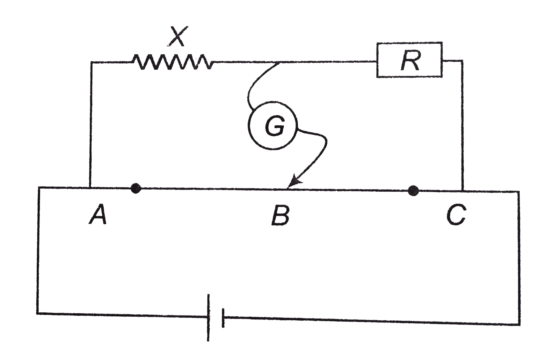
A meter bridge is setup as shown in figure, to determine an unknown resistance X using a standard 10Ω resistor. The galvanometer shows null point when tapping key is at 52cm mark. The end correctiosnn are 1cm and 2cm respectively for the ends A and B. The determined value of X is
 View Solution
Question 42
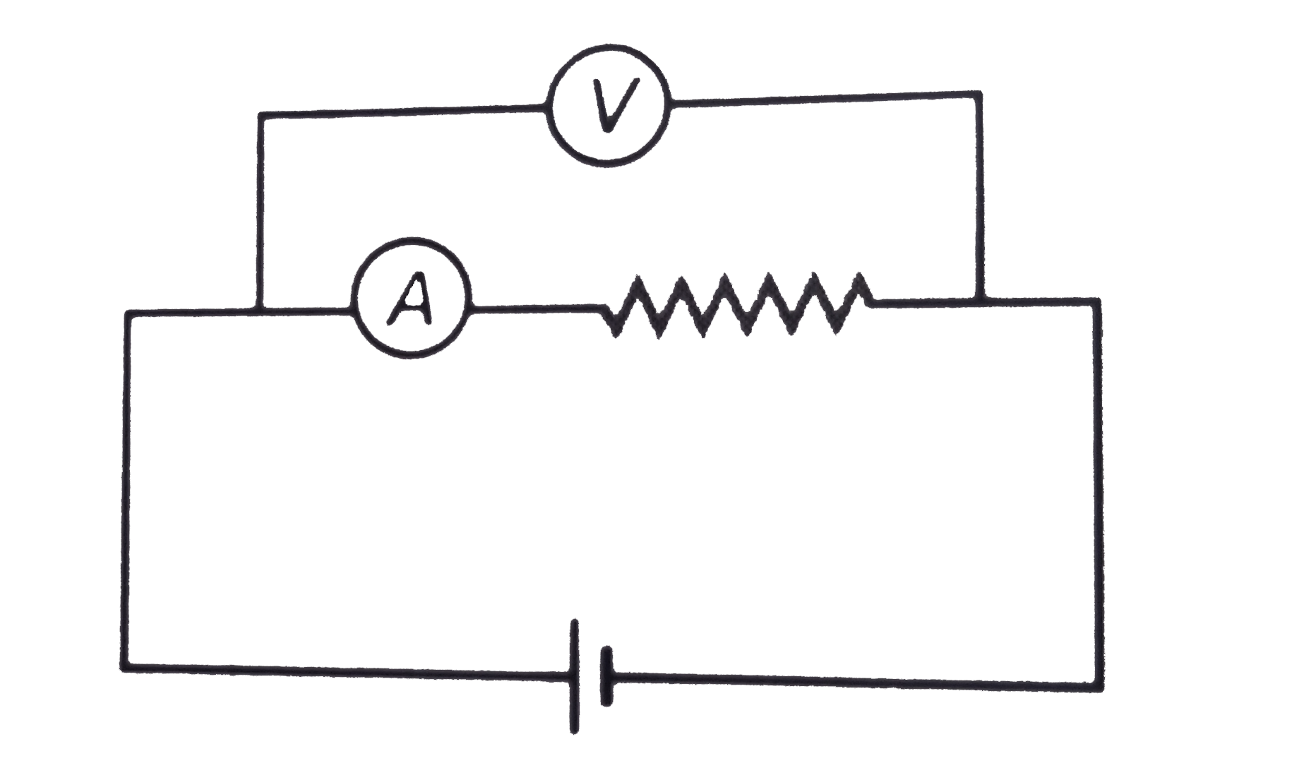
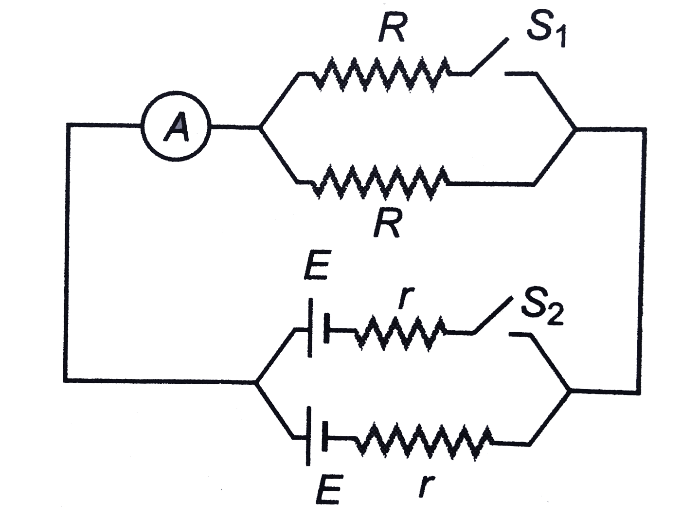
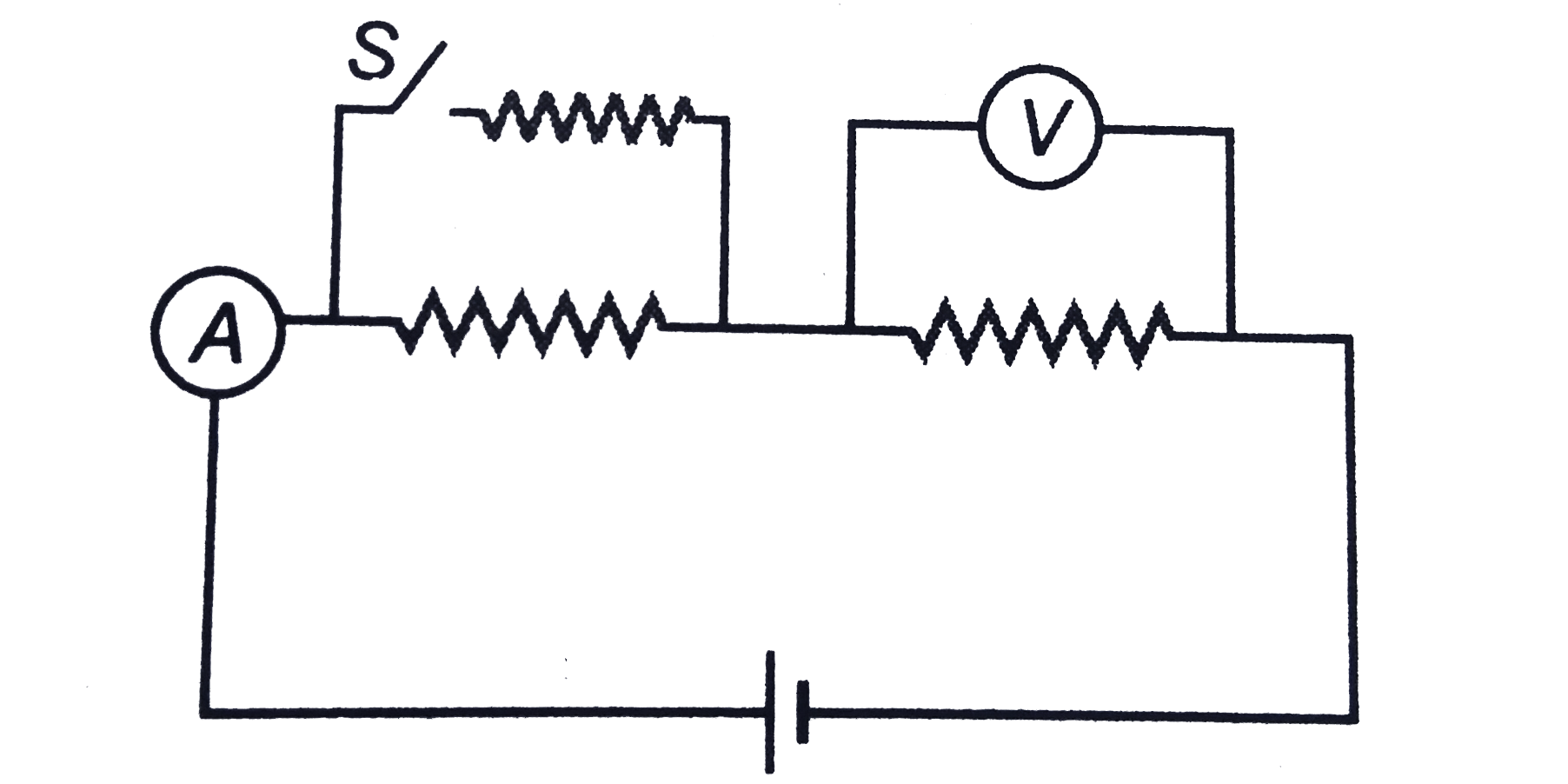
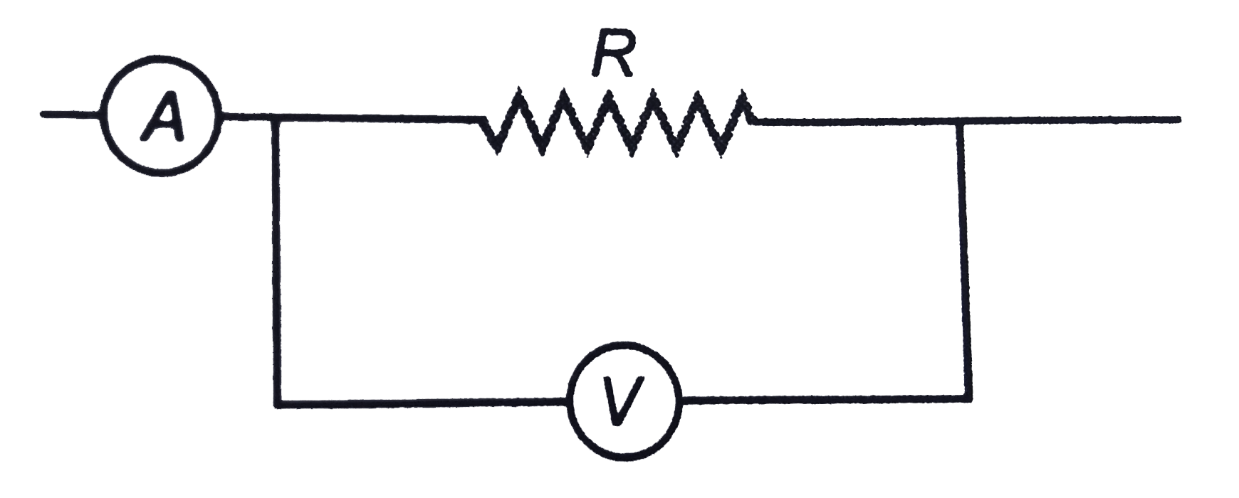
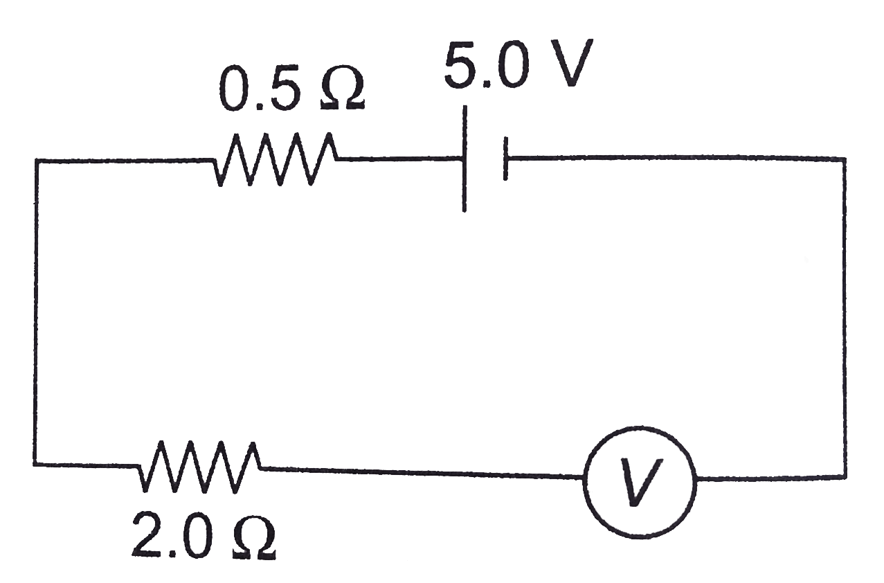
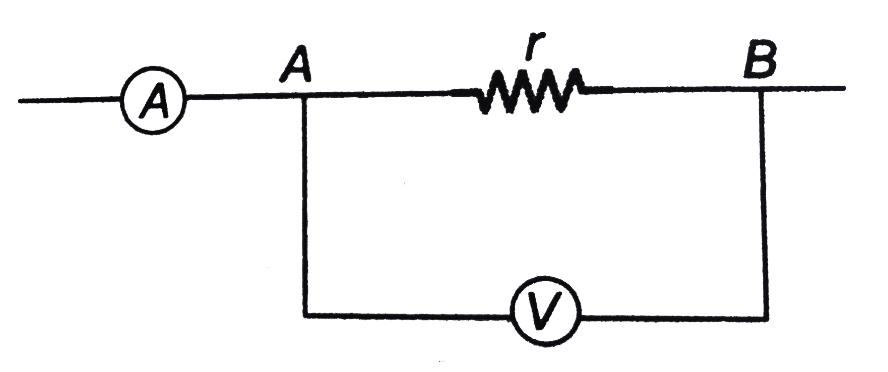
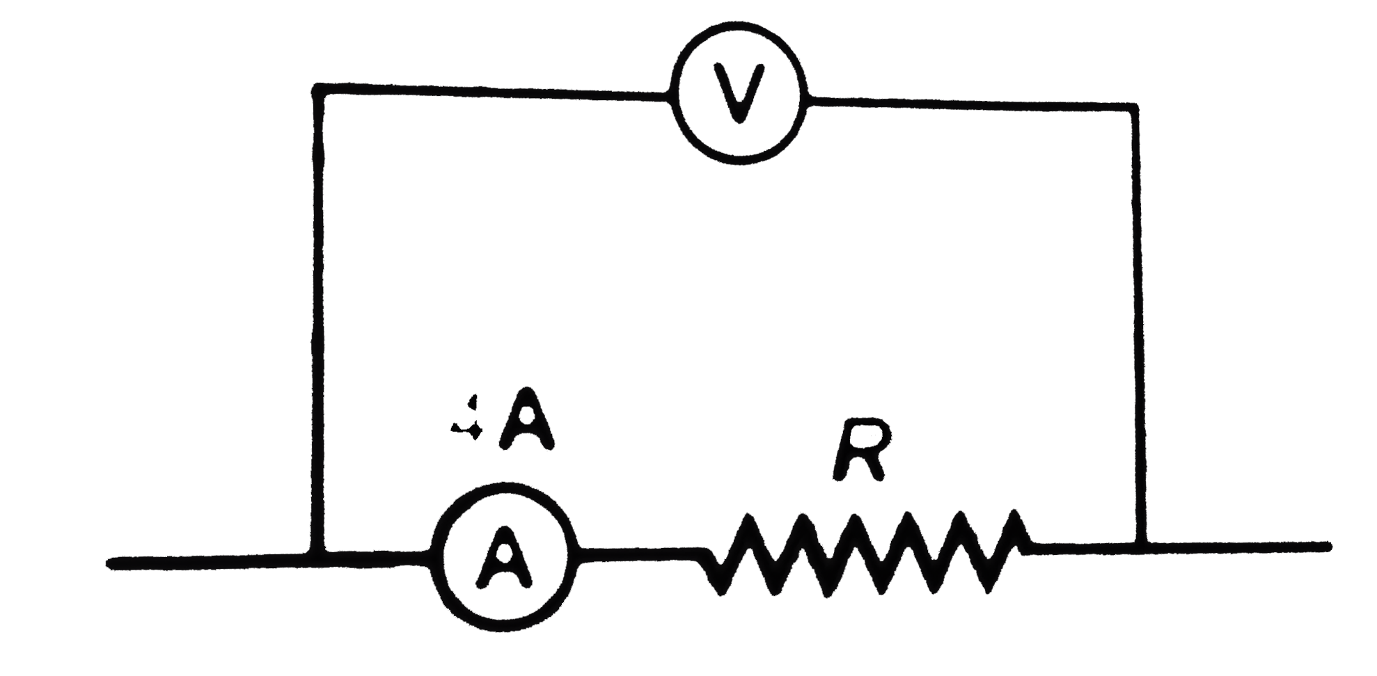
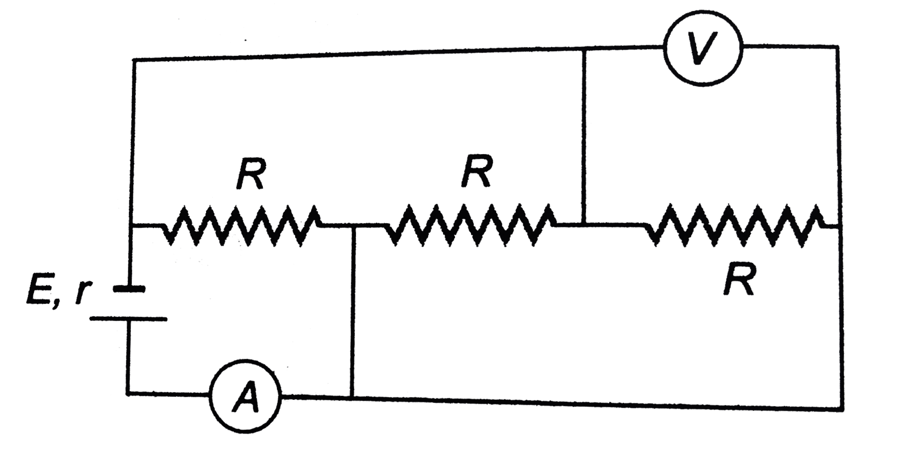
Assertion : In the circuit shown in figure ammeter and voltmeter are non-ideal. Why positions of ammeter and voltmeter are changed, reading of ammeter will increase while of voltmeter will decrease.
Reason : Resistance of an ideal ammeter is zero while that of an ideal voltmeter is infinite. View SolutionQuestion 48
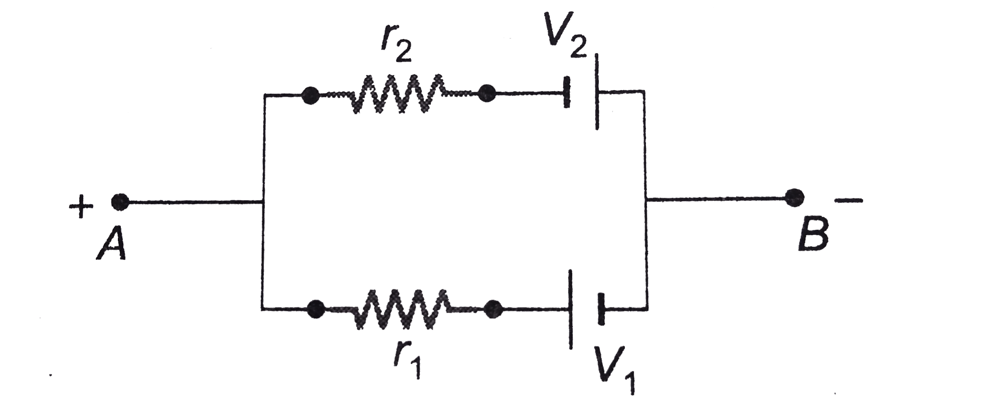
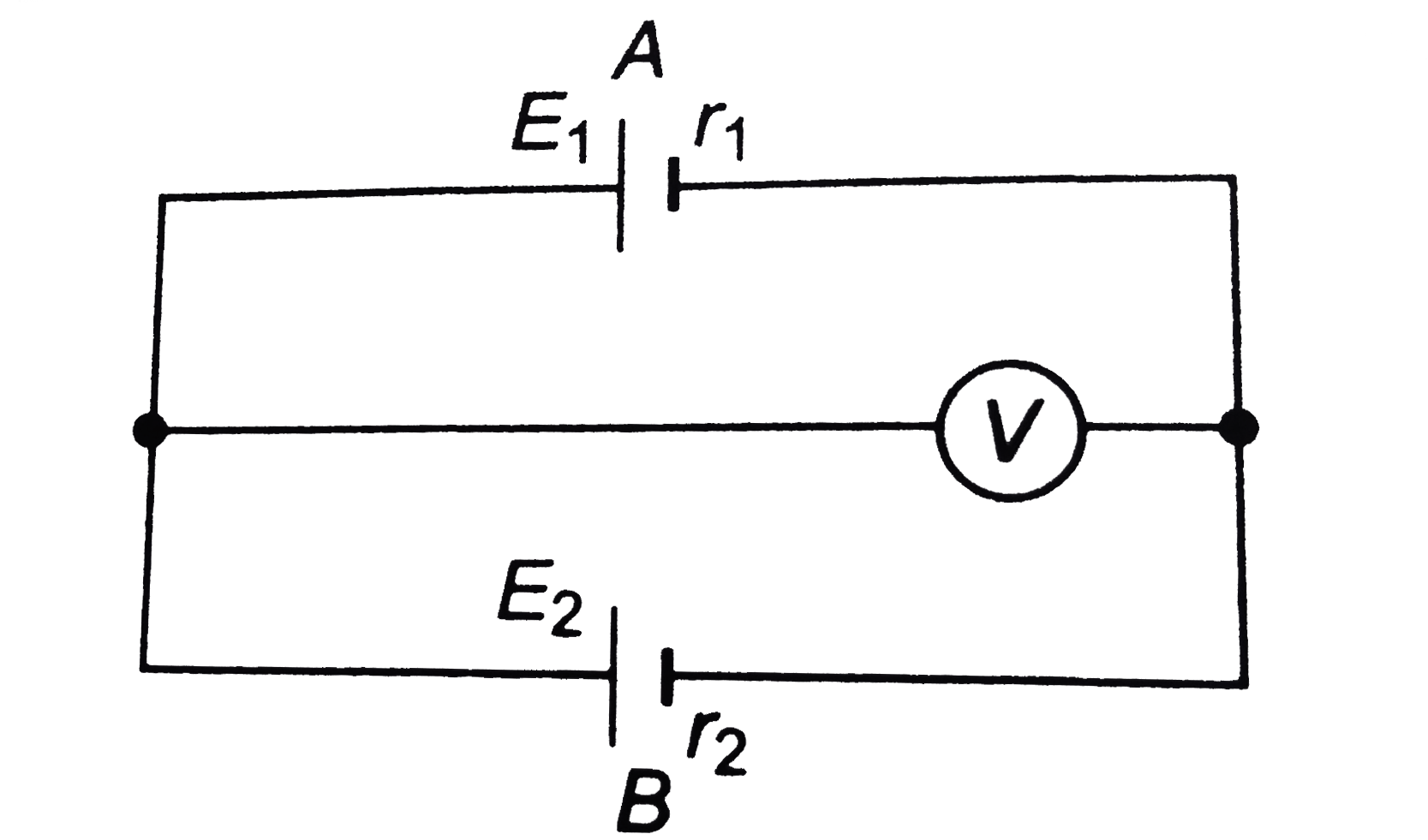
Assertion : Two non-ideal batteries are connected in parallel with same polarities on same: side. The equivalent emf is smaller than either of the two emfs.
Reason : Two non-ideal batteries are connected in parallel, the equivalent inter resistance is smaller than either of the two internal resistances.View SolutionQuestion 100
An aluminium wire carrying a current has diameter 0.84mm. The electric field in the wire 0.49V/m. What is
(a) the current carried by the wire?
(b) the potential difference between two points in the wire 12.0m apart?
(c) the resistance of a 12.0m length of this wire?
Specific resistance of aluminium is 2.75×10⁻⁸Ω−m.View SolutionQuestion 105
An aluminium wire 7.5m long is connected in parallel with a copper wire 6m long. When a current of 5A is passed through the combination, it is found that the current in the aluminium wire is 3A. The diameter of the aluminium wire is 1mm. Determine the diameter of the copper wire. Resistivity of copper is 0.017μΩ−m and that of the aluminium is 0.028μΩ−m.View SolutionQuestion 107
A rectangular block of metal of resistivity p has dimensions d×2d×3d. A potential difference V is applied between two opposite faces of the block.
(a) To which two faces of the block should the potential difference V be applied to give the maximum current density? What is the maximum current density?
(b) To which two faces of the block should the potential difference V be applied to give the maximum current? What is this maximum current? View SolutionQuestion 108
An electrical conductor designed to carry large currents has a circular cross-section 2.50mm in diameter and is 14.0m long. The resistance between its ends is 0.104Ω .
(a) What is the resistivity of the material?
(b) If the electric field magnitude in the conductor is 1.28V/m, what is the total current?
(c) If the material has 8.5x1028 free electrons per cubic metre, find the average drift speed under the conditions of part (b). View SolutionQuestion 116
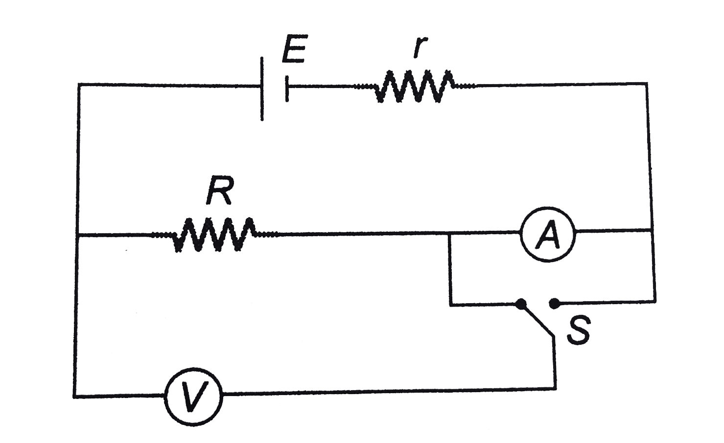
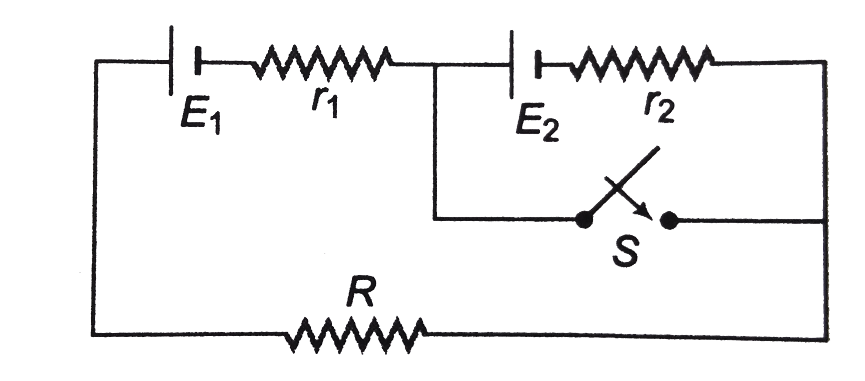
The emf E and the internal resistance r of the battery shown in figure are 4.3V and 1.0Ω respectively. The external resistance R is 50Ω. The resistances of the ammeter and voltmeter are 2.0Ω and 200Ω respectively.
(a) Find the readings of the two meters.
(b) The switch is thrown to the other side. What will be the readings of the two meters now?
 View Solution
Question 119
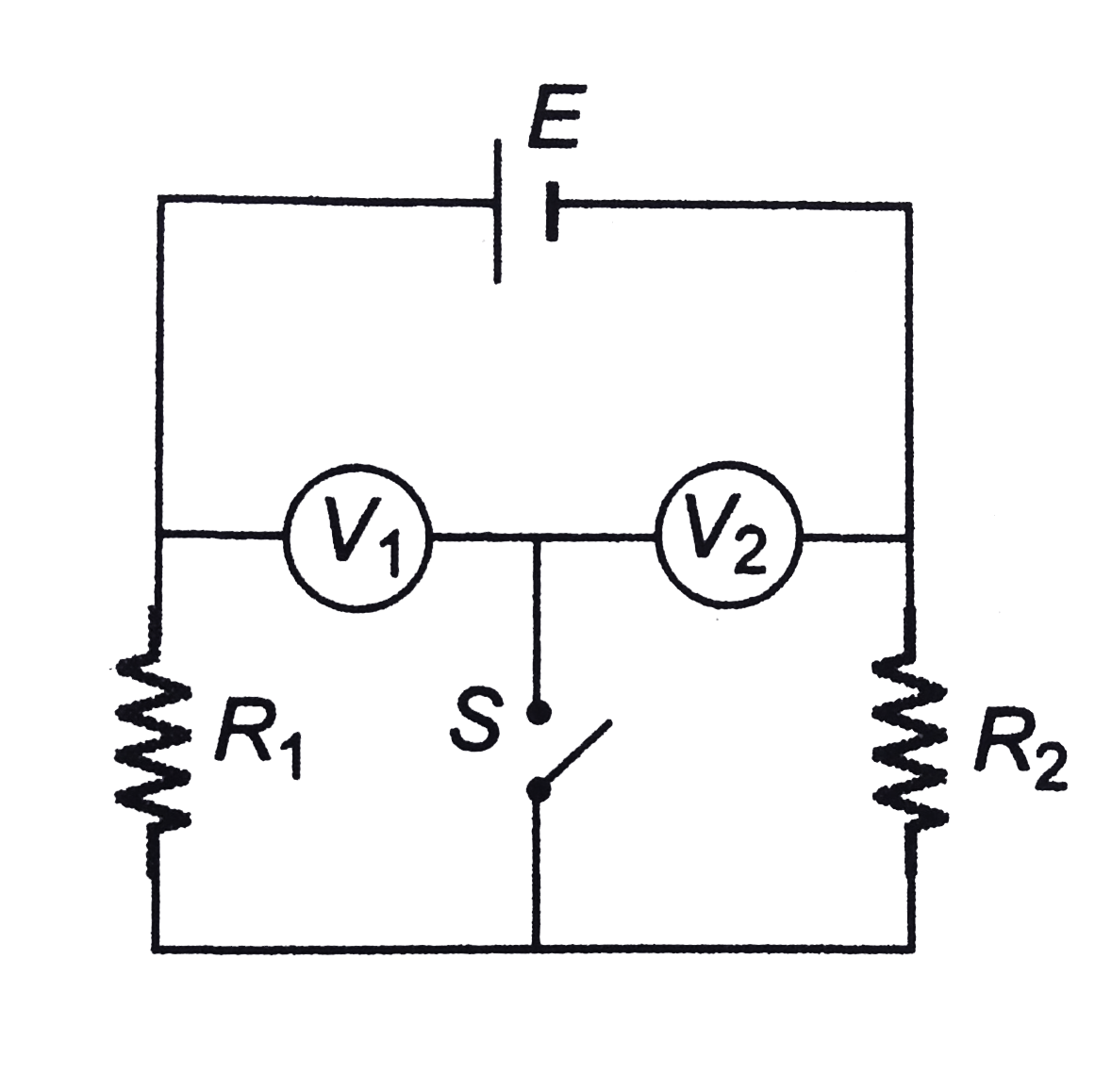
In the circuit shownin figure V1 and V2 are two voltmeter of resistances 3000Ω and 2000Ω respectively. In additions R1=2000Ω, R2=3000ω and E=200V then
a. Fid the reading of voltmeters V1 and V2 when
i. switch S is open
ii. Switch S is closed
b. Current through S, when it is closed (Disregard the resistance of battery)
 View Solution
Question 120
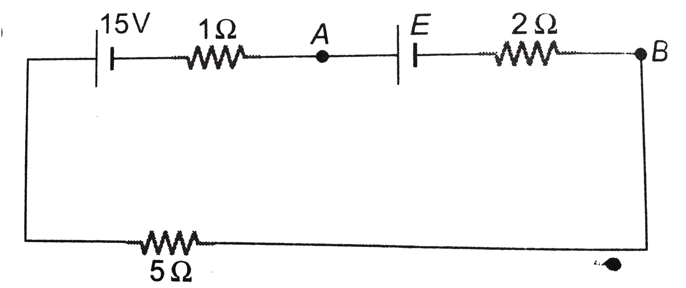
In figure circuit section AB absorbs energy at the rate of 5.0W when a currenti=1.0A passes through it in the indicated direction.
(a) What is the potential difference between points A and B?
(b) Emf device X does not have internal resistance. What is its emf?
(c) What is its polarity (the orientation of its positive and negative terminals)?
 View Solution
Question 121
The potential difference across the terminals of a battery is 8.4V when there is a current of 1.50A in the battery from the negative to the positive terminal. When the current is 3.50Air, the reverse direction, the potential difference becomes 9.4V.
(a) What is the internal resistance of the battery?
(b) What is the emf of the battery? View SolutionQuestion 128
A moving coil galvanometer of resistance 20Ω gives a full scale deflection when a current of 1mA is passed through it. It is to be converted into an ammeter reading 20A on full scale. But the shunt of 0.005Ω only is available. What resistance should be connected in series with the galvanometer coil?View SolutionQuestion 129
A cell of emf 3.4V and internal resistance 3Ω is connected to an ammeter having resistance 2Ω and to an external resistance of 100Ω. When a voltmeter is connected across the 100Ω resistance, the ammeter reading is 0.04A. Find the voltage reading by the voltmeter and its resistance. Had the voltmeter been an ideal one what would have been its reading? View SolutionQuestion 130
(a) A voltmeter with resistance Rv is connected across the terminals of a battery of emf E and internal resistance r. Find the potential difference measured by the voltmeter.
(b) IfE=7.50V and r=0.45Ω, find the minimum value of the voltmeter resistance Rv so that the voltmeter reading is within 1.0% of the emf of the battery. (c) Explain why your answer in part (b) represents a minimum value.View SolutionQuestion 131
An ammeter with resistance RA is connected in series with a resistor R, a battery of emf c and internal resistance r. The current measured by the ammeter is IA. Find the current through the circuit if the ammeter is removed so that the battery and the resistor form a complete circuit. Express your answer in terms of IA,r,RA and R. Show that more "ideal" the ammeter, the smaller the difference between this current and the current IA. ltbr> (b) If R=3.80Ω,ε=7.50V and r=0.45Ω, find the maximum value of the ammeter resistance RA so that IA is within 99% of the current in the circuit when the ammeter is absent. (c) Explain why your answer in part (b) represents a maximum value. View SolutionQuestion 133
A storage battery with emf 2.6V loaded with external resistance produces a current 1A. In this case, the potential difference between the terminals of the storage battery equals 2V. Find the thermal power generated in the battery and the net power supplied by the battery for external circuit.View SolutionQuestion 136
Three resistors having resistances of 1.60Ω,2.40Ω and 4.80Ω are connected in parallel to a 28.0V battery that has negligible internal resistance. Find
(a) the equivalent resistance of the combination.
(b) the current in each resistor.
(c) the total current through the battery.
(d) the voltage across each resistor.
(e) the power dissipated in each resistor.
(f) which resistor dissipates the maximum power the one with the greatest resistance or the least resistance? Explain why this should be.View SolutionQuestion 137
The power of resistor is the maximum power the resistor can safely dissipate without too rise in temperature. The power rating of a 15kΩ resistor is 5.0W. What is the maximum allowable potential difference across the terminals of the resistor?
(b) A 9.0kΩ resistor is to be connected across a 120V potential difference. What power rating is required? View SolutionQuestion 144
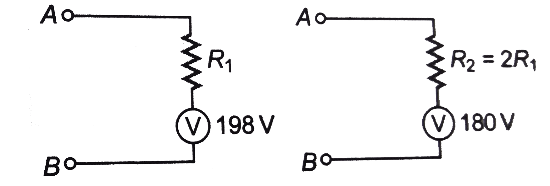
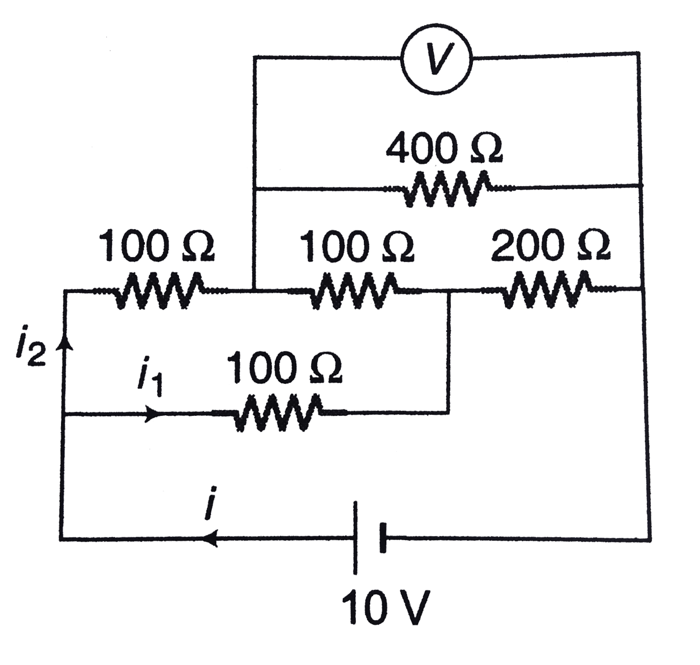
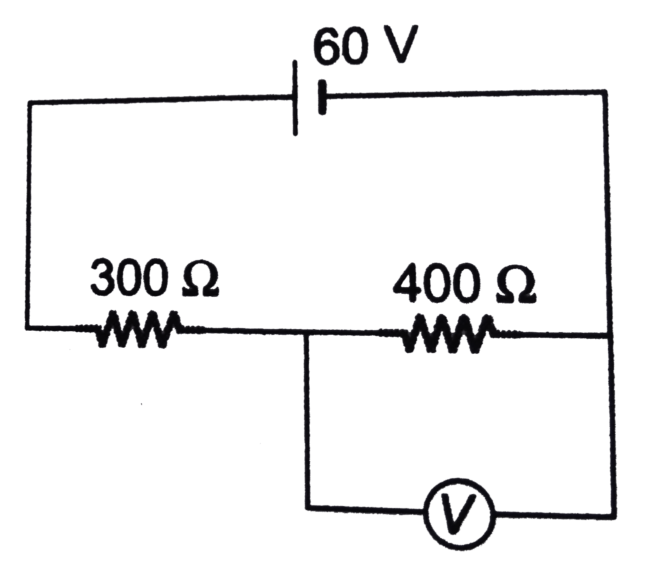
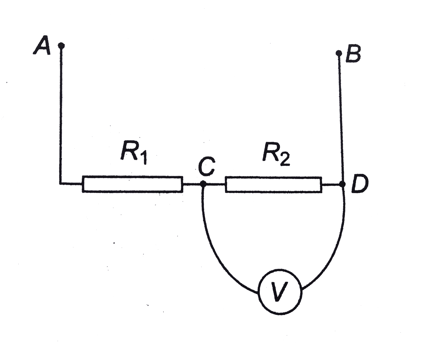
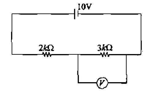
A voltmeter connected in series with a resistance R1 to a circuit indicates a voltage V1=198V. When a series resistor R2=2R1 is used, the voltmeter indicates as voltage V2=180V. If the resistance of the voltmeter is RV=900Ω, then the applied voltage ( in volt ) across A and B is
 View Solution
Question 147
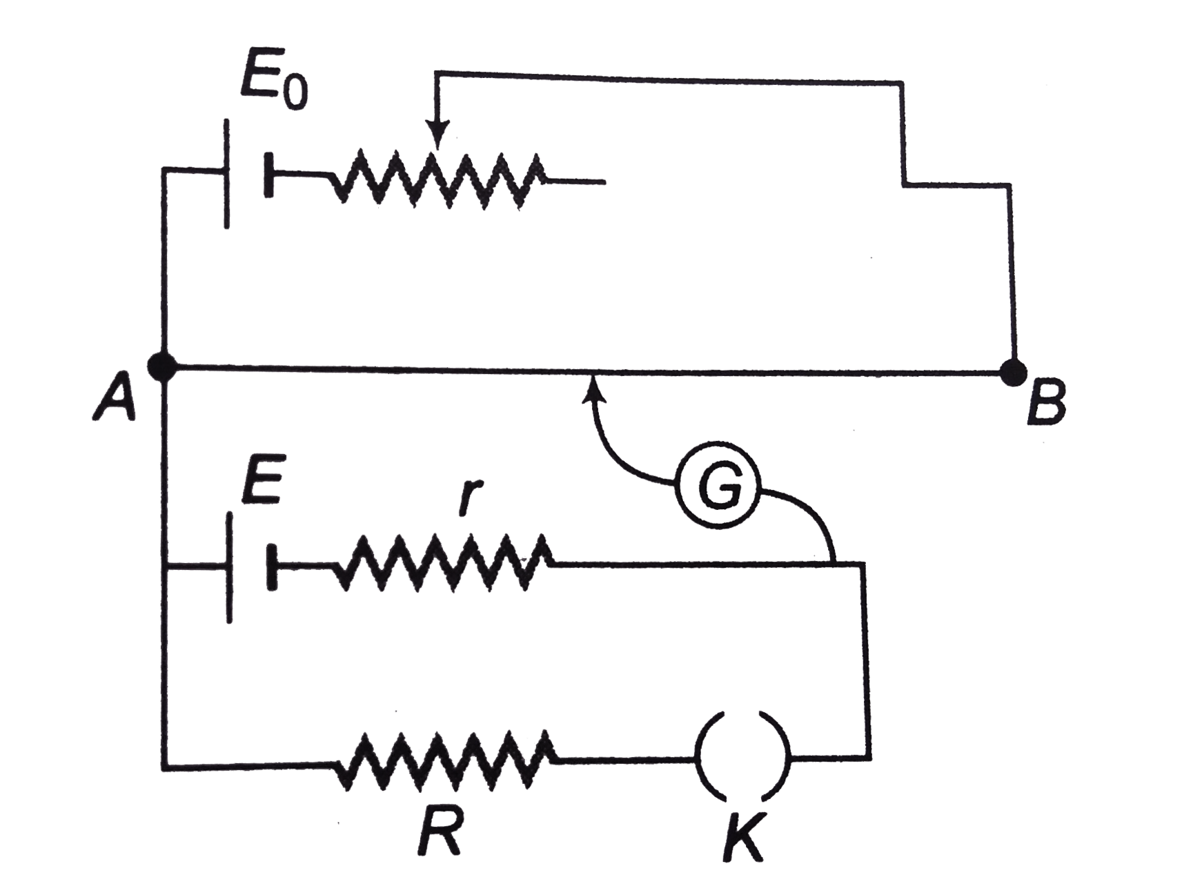
The given figure represents an arrangement of potentiometer for the calculation of internal resistance (r) of the unknown battery (E). The balance length is 70.0cm with the key opened and 60.0cm with the key closed. R is 132.40Ω. The internal resistance (r) of the uknown cell will be
 View Solution
Question 151
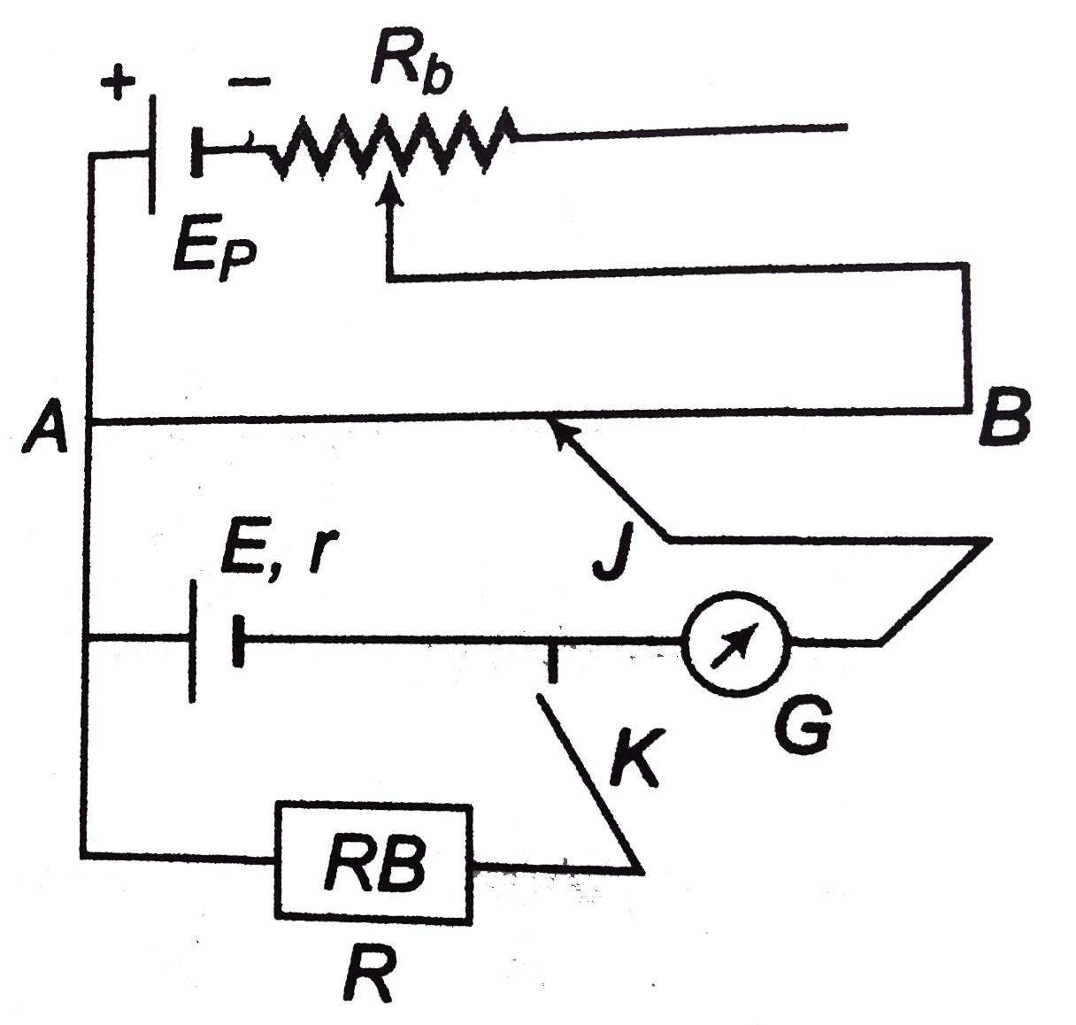
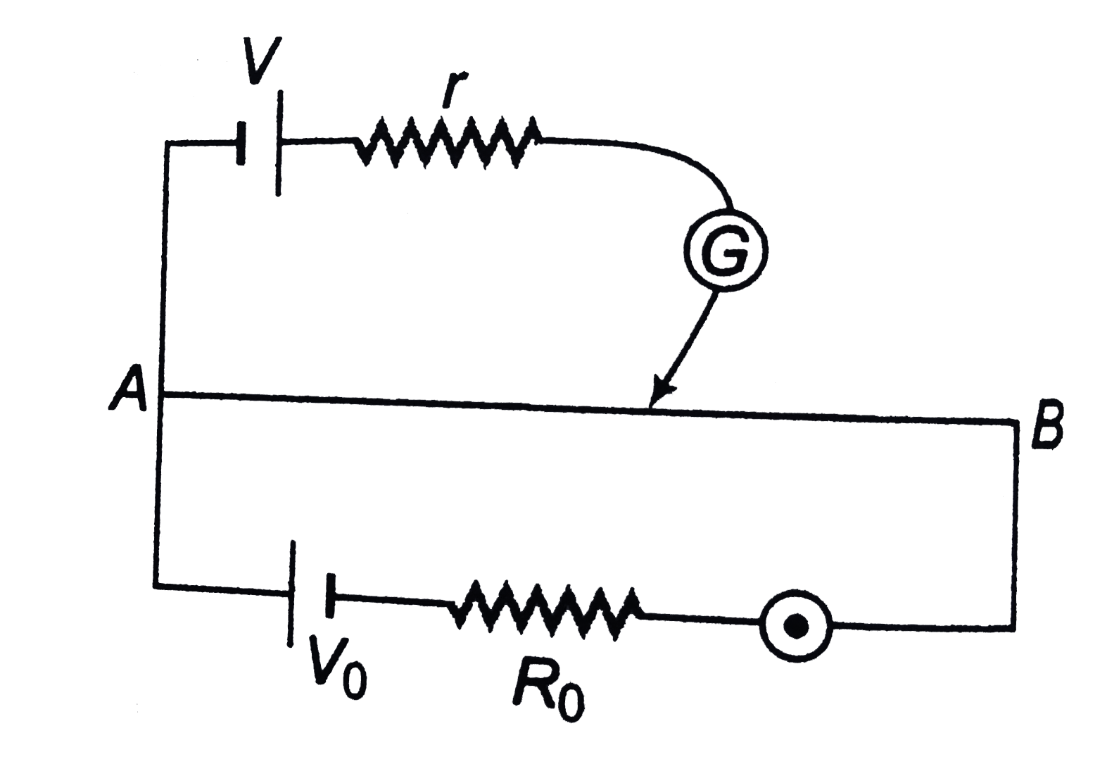
In an experiment on the measurement of internal resistance of as cell by using a potentionmeter, when the key K is kept open then balancing length is obtained at y metre. When the key K is closed and some resistance R is inserted in the resistance box, then the balancing length is found to be x metre. Then the internal resistance is
 View Solution
Question 156
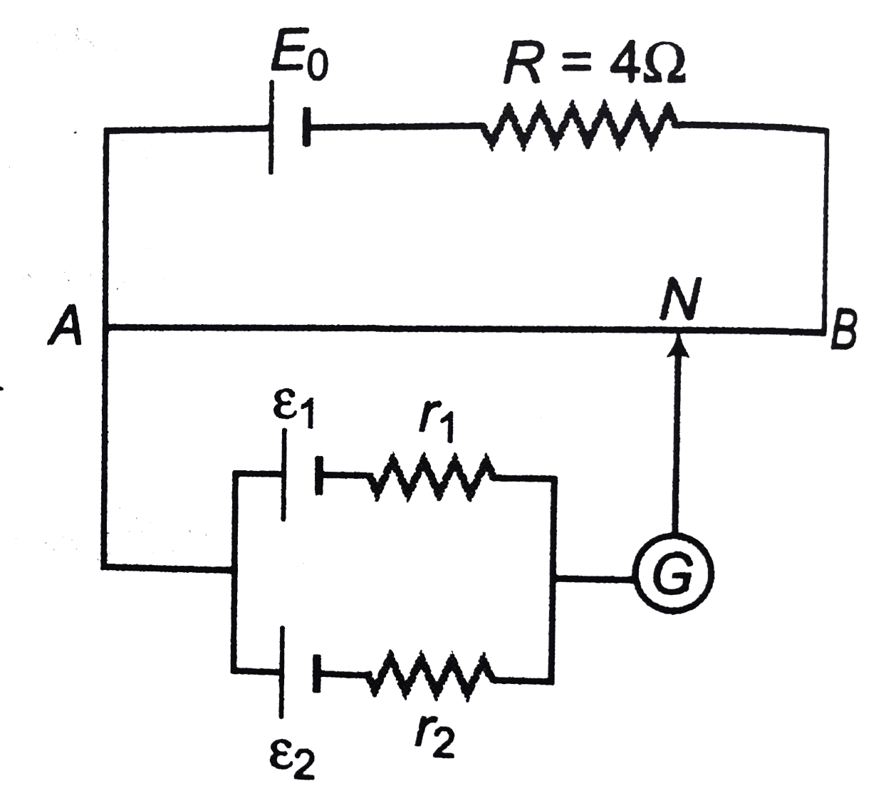
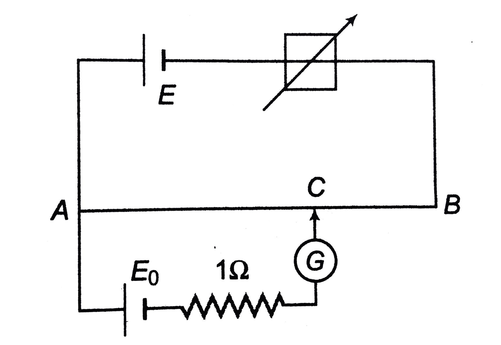
A battery of emf E0=12V is connected across a 4m long uniform wire having resistance 4Ω/m. The cell of small emfs ε1=2V and ε2=4V having internal resistance 2Ω and 6Ω respectivley are connected as shown in the figure. If galvanometer shows no diflection at the point N the distance of points N from the point A is equal to
 View Solution
Question 169
Two heaters designed for the same voltage V have different power ratings. When connected individually across as source of voltageV, they produce H amount of heat each in time t1 and t2 respectively. When used together acros the same source, they produce H amount of heat in time t View SolutionQuestion 179
The length of a potentiometer wire is 600cm and it carries a current of 40mA. For a cell of emf 2V and internal resistance 10Ω, the null point is found to be at 500cm. On connecting a voltmeter across the cell, the balancing length is decreased by 10cm
The voltmeter reading will beView SolutionQuestion 180
The length of a potentiometer wire is 600 cm and it carries a current of 40mA. For a cell of emf 2V and internal resistance 10Ω, the null point is found to be at 500cm. On connecting a voltmeter acros the cell, the balancing length is decreased by 10cm
The resistance of the voltmeter is View SolutionQuestion 184
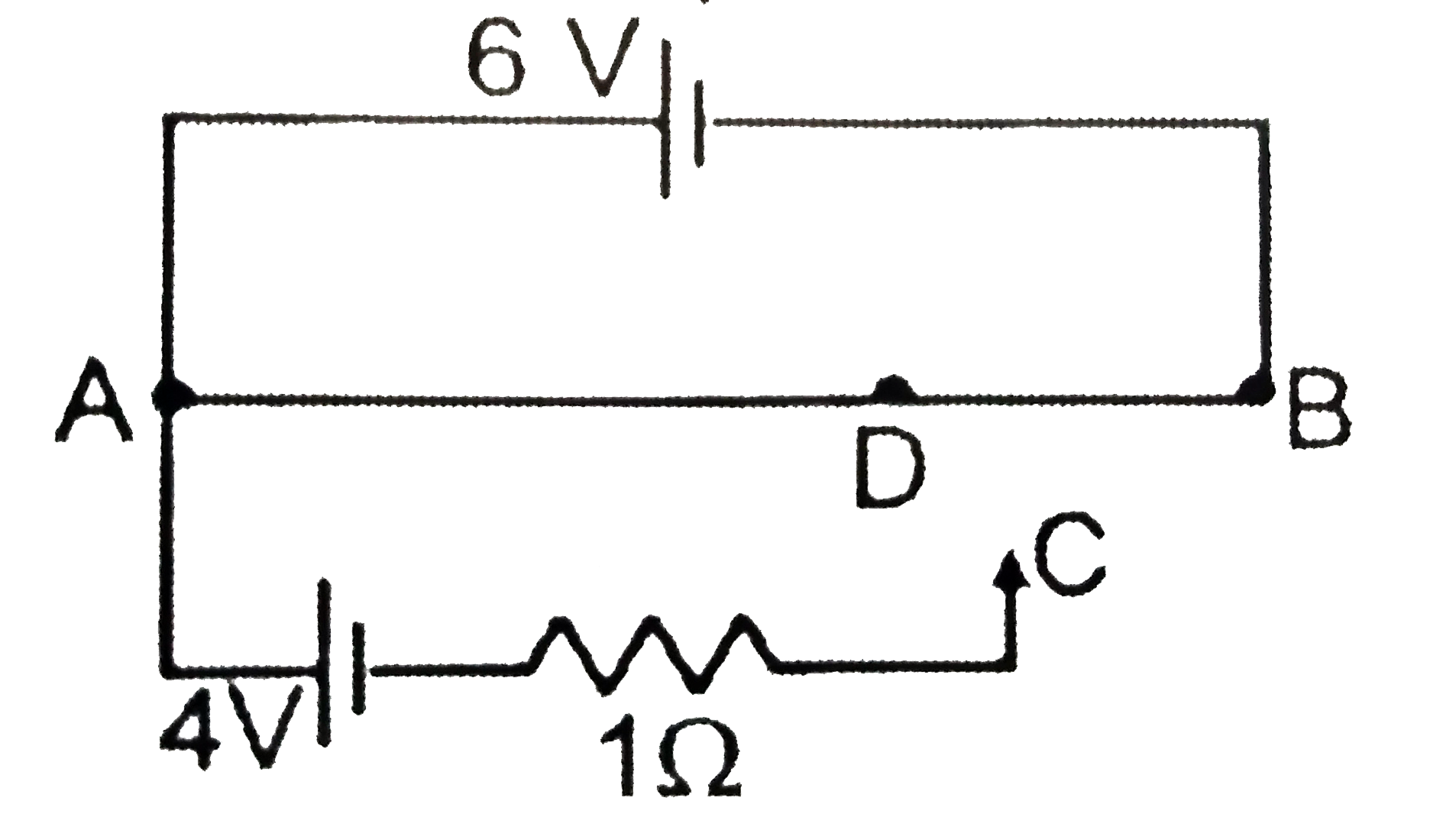
A 6 volt battery of negligible internal resistance is connected across a uniform wire AB of length 100cm. The positive terminal of another battery of emf 4V and internal resistance 1Ω is joind to the point A as shown in figure. Take the potential at B to be zero. (a) What are the potentials at the points A and C ? (b) At which D of the wire AB, the potential is equal to the potential at C. ( c) If the point C and D are connected by a wire. What will be the current through is ? (d) Id the 4V batteryt is replaced by 7.5 V battery, what whould be the answers of parts (a) and (b) ?
 View Solution
Question 185
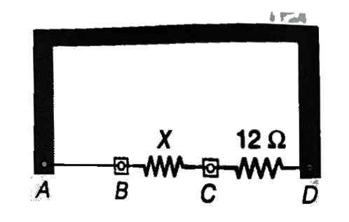
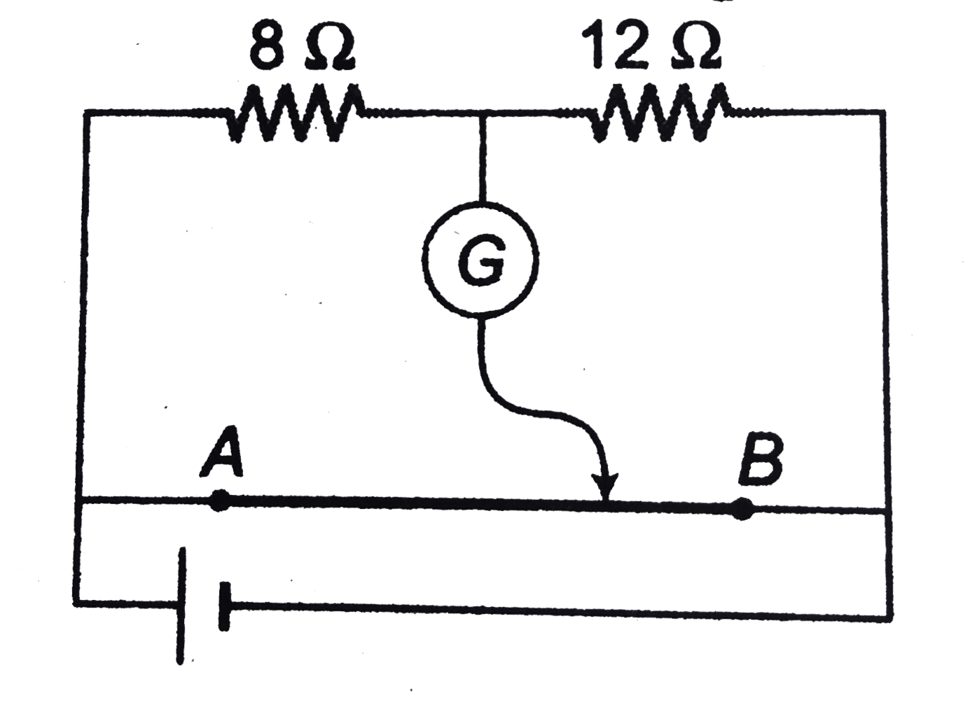
A thin uniform wire AB of length 1m, an unknown resistance X and a resistance of 12Ω are connected by thick conducting strips, as shown in the figure. A battery and a galvanometer (with a sliding jockey connected to it) are also available. Connections are to be made to measure the unknown resistance X. Using the principle of Wheatstone bridge answer the following questions :
(a) Are there positive and negative terminals on the galvanometer?
(b) Copy the figure in your answer book and show the battery and the galvanometer (with jockey connect at appropriate points.
(c) After appropriate connections are made, it is found that no deflection takes place in th, from galvanometer when the sliding jockey touches the wire at a distance of 60cm from A. Obtain value of the resistance X.
 View Solution
Question 186
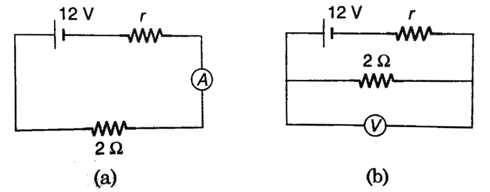
A galvanometer (coil resistance 99Ω.) is converted into an ammeter using a shunt of 1Ω and connected as shown in figure (a). The ammeter reads 3A. The same galvanometer is convened into a voltmeter by connecting a resistance of 101Ω in series. This voltmeter is connected at, shown in figure (b). Its reading is found to be 45 of the full scale reading. Find :
(a) internal resistance r of the cell
(b) range of the ammeter and voltmeter
(c) full scale deflection current of the galvanometer.
 View Solution
Question 190
An accumulator of emf 2V and negligible internal resistance is connected across a uniform wire of length 10 m and resistance 30Ω The appropriate terminals of a cell of emf 1.5V and internal resistance 1Ω is connected to one end of the wire and the other terminal of the cell is connected through a sensitive galvanometer to a slider on the wire. What is the length of the wire that will be required to produce zero deflection of the galvanometer? How will the balancing length change?
(a) When a coil of resistance 5Ω is placed in series with the accumulator.
(b) The cell of 1.5V is shunted with 5Ω resistor? View SolutionQuestion 193
A conductor has a temperature independent resistance R and a total heat capacity C. At the moment t=0 it is connected to a DC voltage V. Find the times dependence of the conductors temperature t assuming the thermal power dissipated into surrounding space to vary as q=k(T−T0) where k is a constant T0 is the surrounding temperature (equal to conductor's temperature at the initial moment).View Solution
All Exercises from DC PANDEY PHYSICS (HINGLISH) Class 12 PHYSICS CURRENT ELECTRICITY
- B. ASSERTION AND REASON
- CHECK POINT
- EXERCISE 23.1
- EXERCISE 23.10
- EXERCISE 23.11
- EXERCISE 23.12
- EXERCISE 23.13
- EXERCISE 23.2
- EXERCISE 23.3
- EXERCISE 23.4
- EXERCISE 23.5
- EXERCISE 23.6
- EXERCISE 23.7
- EXERCISE 23.8
- EXERCISE 23.9
- LEVEL 1 ASSERTION AND REASON
- LEVEL 1 OBJECTIVE
- LEVEL 1 SUBJECTIVE
- LEVEL 2 COMPREHENSION EXAMPLE TYPE
- LEVEL 2 MORE THAN ONE CORRECT
- LEVEL 2 SINGLE CORRECT
- LEVEL 2 SUBJECTIVE
- MATCH THE COLUMNS
- MEDICAL ENTRANCES GALLERY
- OBJECTIVE_TYPE
- TAKING IT TOGETHER
- EXAMPLE
- EXAMPLE EXAMPLE TYPE
- EXAMPLE TYPE 1
- EXAMPLE TYPE 2
- EXAMPLE TYPE 3
- EXAMPLE TYPE 4
- EXAMPLE TYPE 5
- EXAMPLE TYPE 6
- MISCELLANEOUS EXAMPLES





 ,
,  ,
, 
