PRACTICE QUESTIONS (Integer Type) from RESNICK AND HALLIDAY PHYSICS (HINGLISH) ELECTROMAGNETIC INDUCTION for Class 12
| Class 12 | PHYSICS |
| Chapter | ELECTROMAGNETIC INDUCTION |
| RESNICK AND HALLIDAY PHYSICS (HINGLISH) | PRACTICE QUESTIONS (Integer Type) |
| Medium | English |
| Academic Year | 2023-2024 |
Question 5
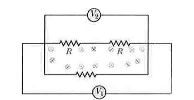
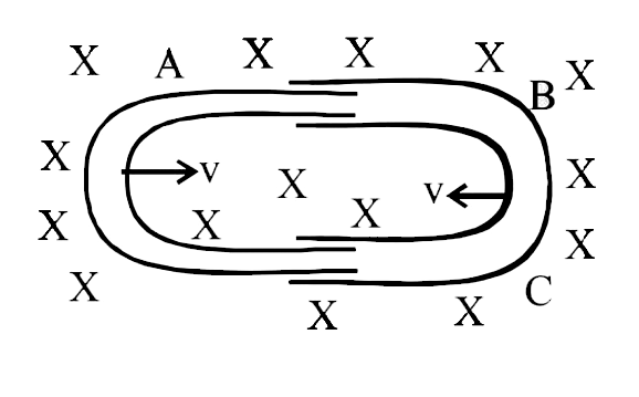
One conducting U tube can slide inside another as shown in figure, maintaining electrical contacts between the tubes. The magnetic field B is perpendicular to the plane of the figure. If each tube maoves towards the other at a constant speed v. Then the emf induced in the circuit in terms of B, l and v where l is the width of each tube will be
 View Solution
Question 17
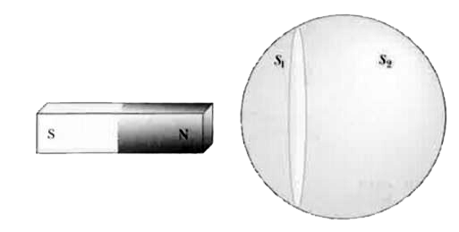
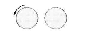
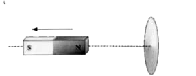
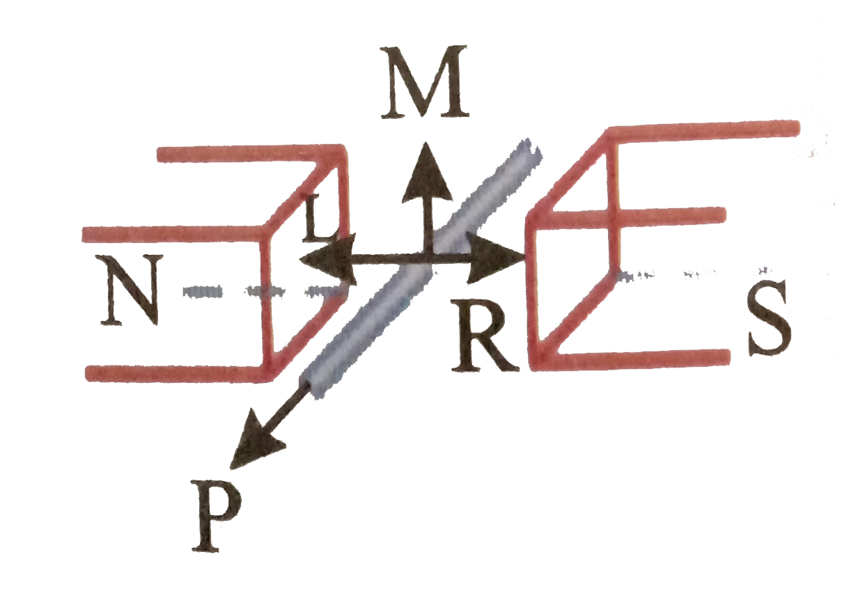
A bar magnet with its north (N) and south (S) poles as shown in the following figure is initially moving to the left, along the axis of, and away from a circular conducting loop. A current l is induced in the loop, with a being the acceleration of the magnet due to this current. As seen from the magnet looking in the direction of the loop,
 View Solution
Question 20
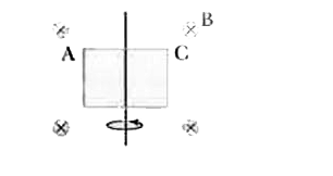
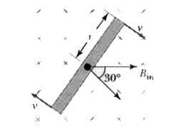
A rectangular loop, in edge view, as shown in the following figure, is rotating in a horizontal magnetic field. The axis of rotation is perpendicular to the page and is shown by a black dot in the middle of the figure. The parts of the loop perpendicular to the page are moving at a velocity v as shown in the figure. At the instant depicted, the normal to the loop makes an angle of 30° with the east direction. Which of the following statements, about the magnetic flux ϕ through the loop and the induced emf in the loop, are true, at the instant depicted?
 View Solution
Question 22
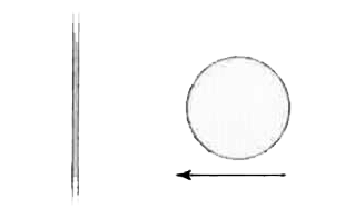
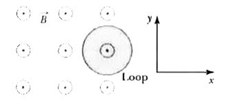
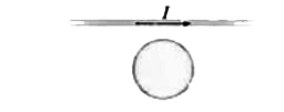
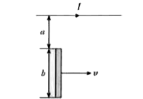
A long straight wire carries a current of 10.05 A to the right. A circular loop of wire lies below the long straight wire, as shown in the following figure. The current in the long straight wire decreases to zero in a time of 4.652 s. What direction does the induced current flow around the circular loop of wire?
 View Solution
Question 25
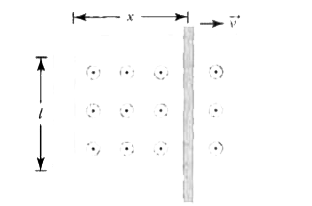
A rod with resistance R lies across frictionless conducting rails in a constant uniform magnetic field →B, as shown in the following figure. Assume the rails have negligible resistance. The magnitude of the force that must be applied by a person to pull the rod to the right at constant speed v is
 View Solution
Question 28
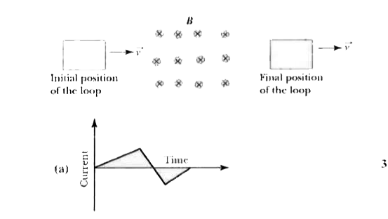
A rectangular loop of wire in the plane of the paper starts outside a perpendicular uniform magnetic field directed into the paper as shown in the following figure. The loop is pulled with a constant velocity through the magnetic field and out the other side. Which of the following graphs would best represent the variation of the electric current in the wire with time?
 View Solution
Question 30
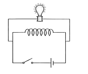
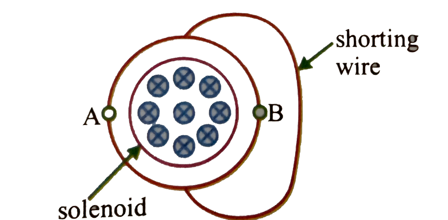
A very long solenoid with its axis perpendicular to the page generates an inward magnetic field whose magnitude increases with time. This induces an emf in a conducting wire loop around the solenoid which lights two identical bulbs A and B connected in series along the wire. Now two points dimetrically opposite on the wire loop are shorted with another conducting wire (having zero resistance) lying to the right og bulb B in the plane of the page. After the shorting wire is inserted:
 View Solution
Question 34
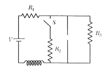
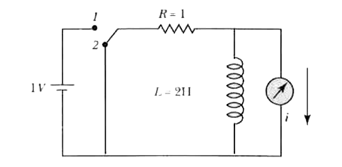
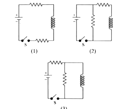
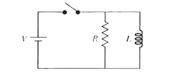
A 2 H coil, a 10 μF resistor, and a 5 V battery are all connected in parallel. After a current is well established through the resistor and inductor, the battery is disconnected from the circuit by opening a switch as shown in the following figure. Immediately after the battery is disconnected, Lenz's law would predict
 View Solution
Question 43
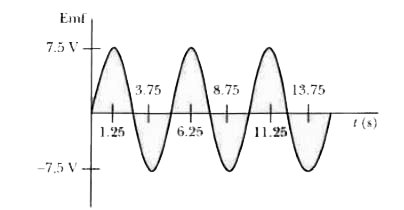
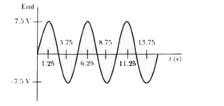
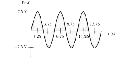
A circular coil of wire has 25 turns and has a radius of 0.075 m. The coil is located in a variable magnetic field whose behavior is shown on the graph. At all times, the magnetic field is directed at an angle of 75° relative to the normal to the plane of a loop. What is the average emf induced in the coil in the time interval from t = 5.00 s to 7.50 s?
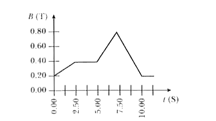 View Solution
Question 46
A conducting rod of length l is hinged at point O. It is a free to rotate in a verical plane. There exists a uniform magnetic field B in horizontal direction. The rod is released from the position shown. The potential difference between the two ends of the rod is proportional to
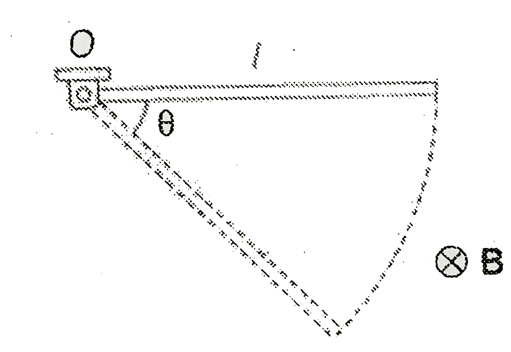 View Solution
Question 47
A circular conducting loop of radius r0 and having resistance per unit length lamba as shown in the figure is placed in a magnetic field B which is constant in space and time. The ends of the loop are crossed and pulled in opposite directions with a velocity v such that the loop always remains circular and the radius of the loop goes on decreasing then
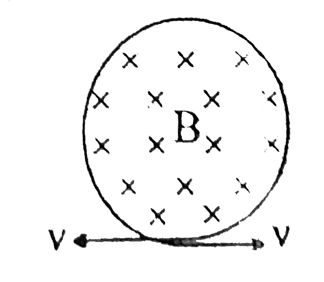 View Solution
Question 49
Two different coils have self-inductances L1=8mHandL2=2mH. The current in one coil is increased at a constant rate. The current in the second coil is also increased at the same constant rate. At a certain instant of time, the power given to the two coil is the same. At that time, the current, the induced voltage and the energy stored in the first coil are i1,V1andW1 respectively. Corresponding values for the second coil at the same instant are i2,V2andW2 respectively. Then:View SolutionQuestion 53
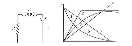
A loop is formed by two parallel conductors connected by a solenoid with inductance L and a conducting rod of mass M which can freely slide over the conductors. The conductors are located in a uniform magnetic field with induction B perpendicular to the plane of loop. The distance between conductors is l. At t = 0, the rod is given a velocity v0 directed toward right and the current through the inductor is initially zero (below figure) .
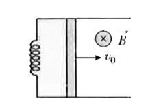 View Solution
Question 55
A conducting rod of length is moved at constant velocity v0 on two parallel, conducting, smooth, fixed rails, that are placed in a uniform constant magnetic field B perpendicular to the plane for the rails as shown in Fig. A resistance R is connected between the two ends of the rails.
Then which of the following is/are correct:
 View Solution
Question 56
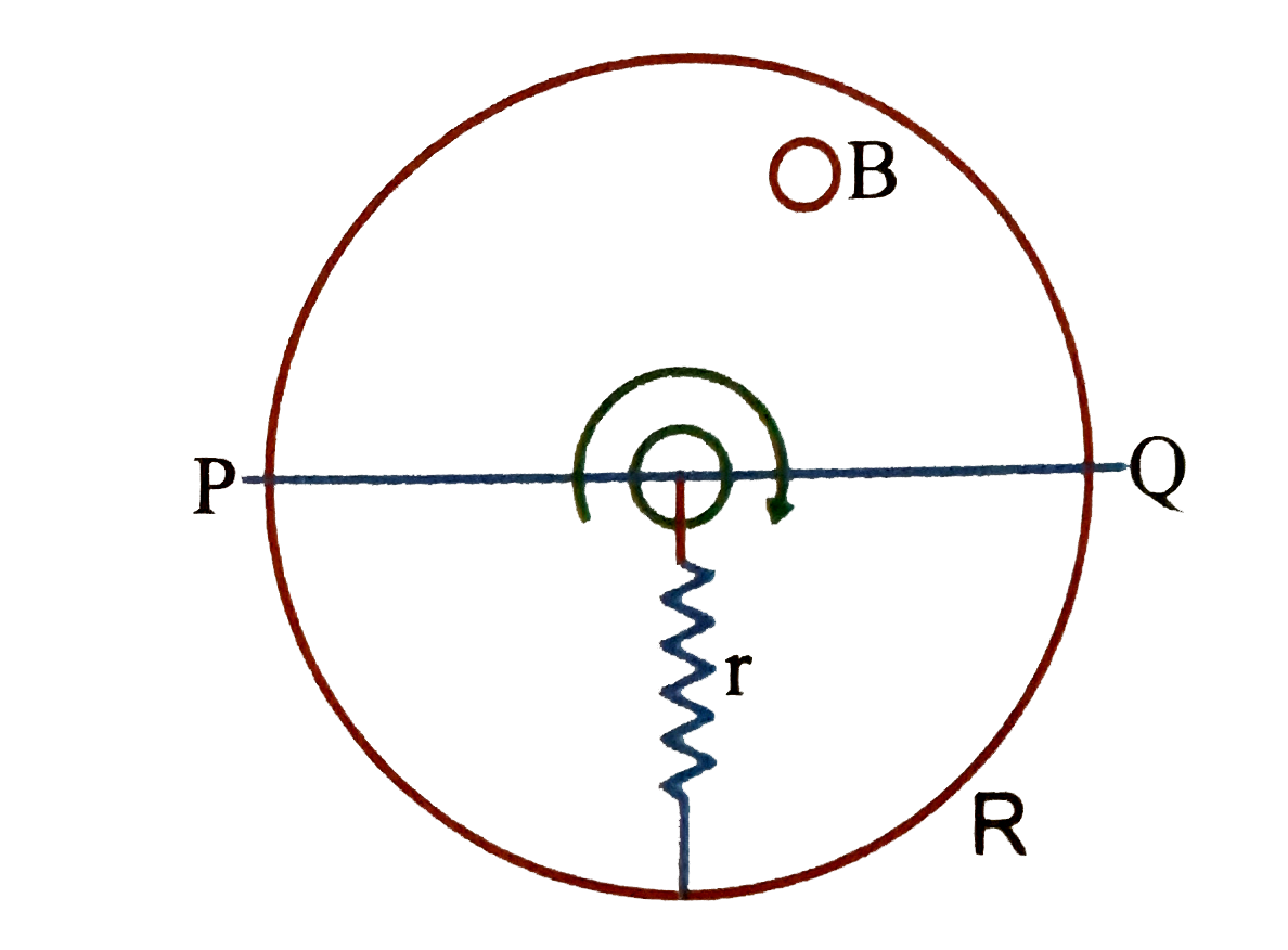
In the figure shown 'R' is a fixed conducting fixed ring of negligible resistance and radius 'a' PQ is a uniform rod of resistance r. It is hinged at the centre of the ring and rotated about this point in clockwise direction with a uniform angular velocity w. These is a uniform magnetic filled of strength 'B' ponting inwards. 'r' is a stationary resistance
 View Solution
Question 59
The figure shows a uniform, 3.0 T magnetic field that is normal to the plane of a conducting, circular loop with a resistance of 1.5 Ω and a radius of 0.024 m. The magnetic field is directed out of the paper as shown . Note: The area of the non-circular portion of the wire is considered negligible compared to that of the circular loop.
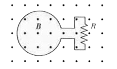
What is the magnitude of the average induced emf in the loop if the magnitude of the magnetic field is doubled in 0.4 s?View SolutionQuestion 60
The figure shows a uniform, 3.0 T magnetic field that is normal to the plane of a conducting, circular loop with a resistance of 1.5 Ω and a radius of 0.024 m. The magnetic field is directed out of the paper as shown . Note: The area of the non-circular portion of the wire is considered negligible compared to that of the circular loop.
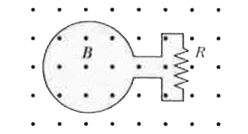
What is the average current around the loop if the magnitude of the magnetic field is doubled in 0.4 s?View SolutionQuestion 61
The figure shows a uniform, 3.0 T magnetic field that is normal to the plane of a conducting, circular loop with a resistance of 1.5 Ω and a radius of 0.024 m. The magnetic field is directed out of the paper as shown . Note: The area of the non-circular portion of the wire is considered negligible compared to that of the circular loop.
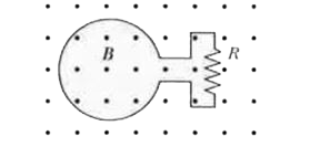
If the magnetic field is held constant at 3.0 T and the loop is pulled out of the region that contains the field in 0.2 s, what is the magnitude of the average induced emf in the loop?View SolutionQuestion 62
The figure shows a uniform, 3.0 T magnetic field that is normal to the plane of a conducting, circular loop with a resistance of 1.5 Ω and a radius of 0.024 m. The magnetic field is directed out of the paper as shown . Note: The area of the non-circular portion of the wire is considered negligible compared to that of the circular loop.
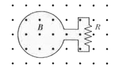
If the magnetic field is held constant at 3.0 T and the loop is pulled out of the region that contains the field in 0.2 s, at what rate is energy dissipated in R?View SolutionQuestion 63
A flexible circular loop 20cm in diameter lies in a magneic field with magnitude 1.0T, direction lies into the plane of the page as shown in Fig. 3.187. The loop is pulled at the points indicated by the arrws, forming a loop of zero area in 0.314s.
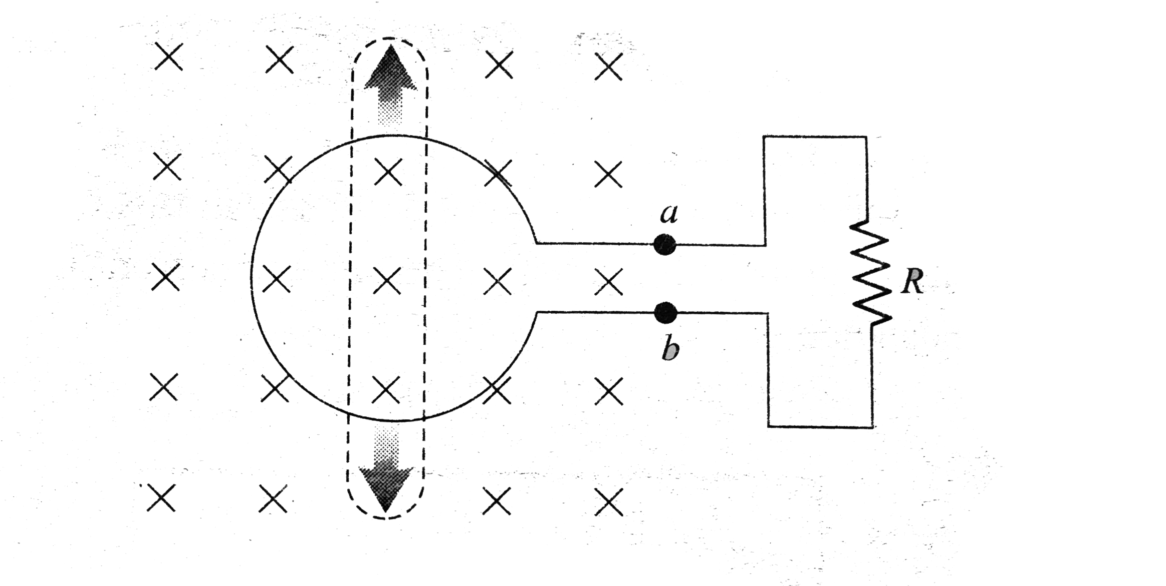
The average induced emf in the circuit is View SolutionQuestion 64
A flexible circular loop 20cm in diameter lies in a magneic field with magnitude 1.0T, direction lies into the plane of the page as shown in Fig. 3.187. The loop is pulled at the points indicated by the arrws, forming a loop of zero area in 0.314s.
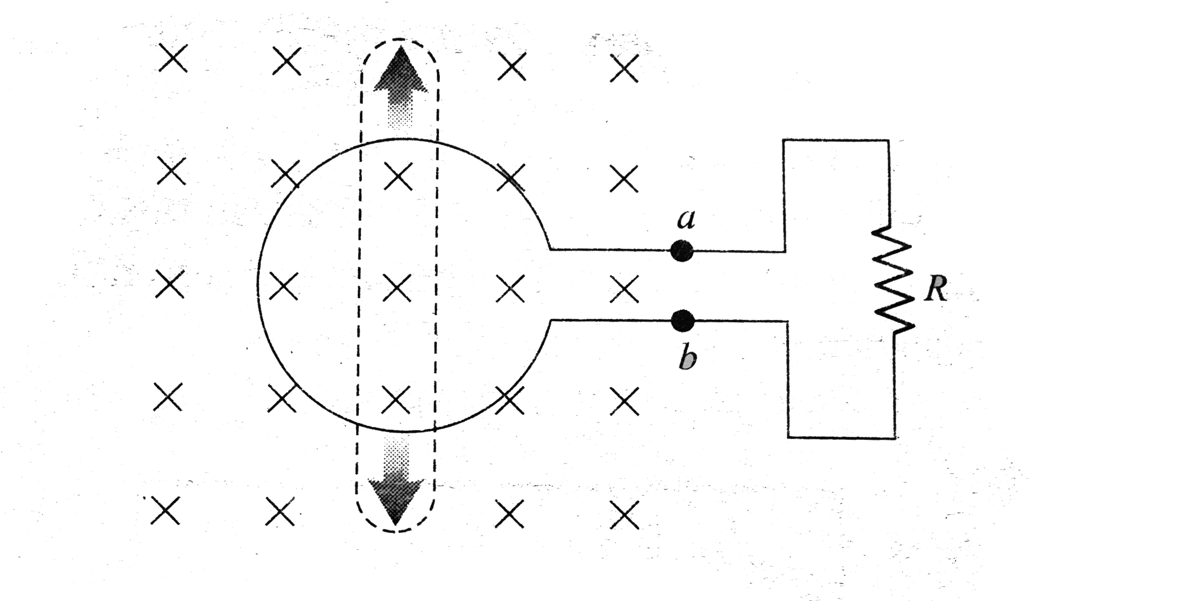
if R=0,01Ω, the magnitude and direction of current flowing in the loop areView SolutionQuestion 65
A wire loop enclosing a semicircle of radius R is located on the boundary of a uniform magnetic field B. At the moment t=0, the loop is set into rotation with constant angular acceleration α about an axis O. The clockwise emf direction is taken to be positive.
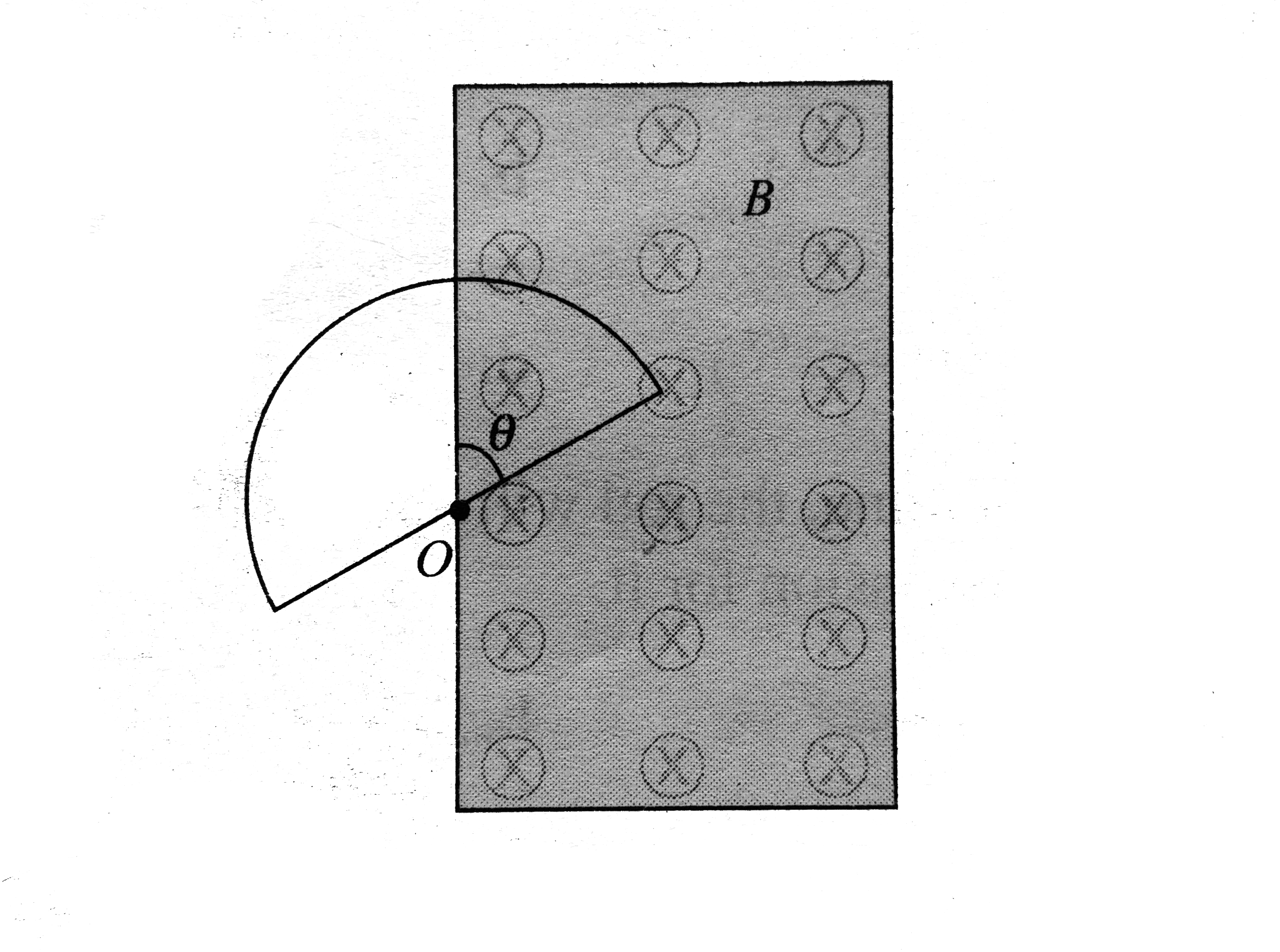
The variation of emf as function of time is View SolutionQuestion 66
A wire loop enclosing a semicircle of radius R is located on the boundary of a uniform magnetic field B. At the moment t=0, the loop is set into rotation with constant angular acceleration α about an axis O. The clockwise emf direction is taken to be positive.
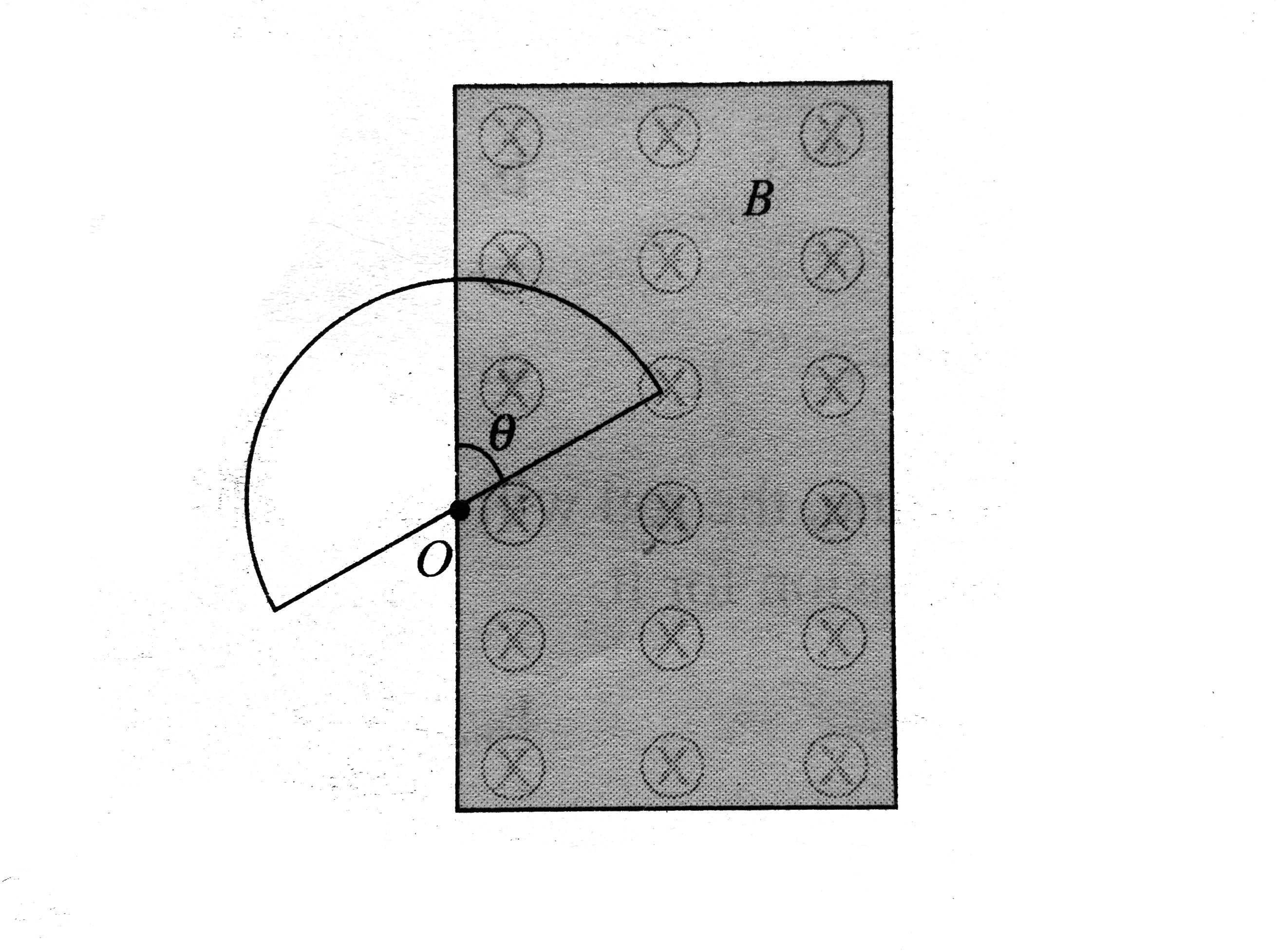
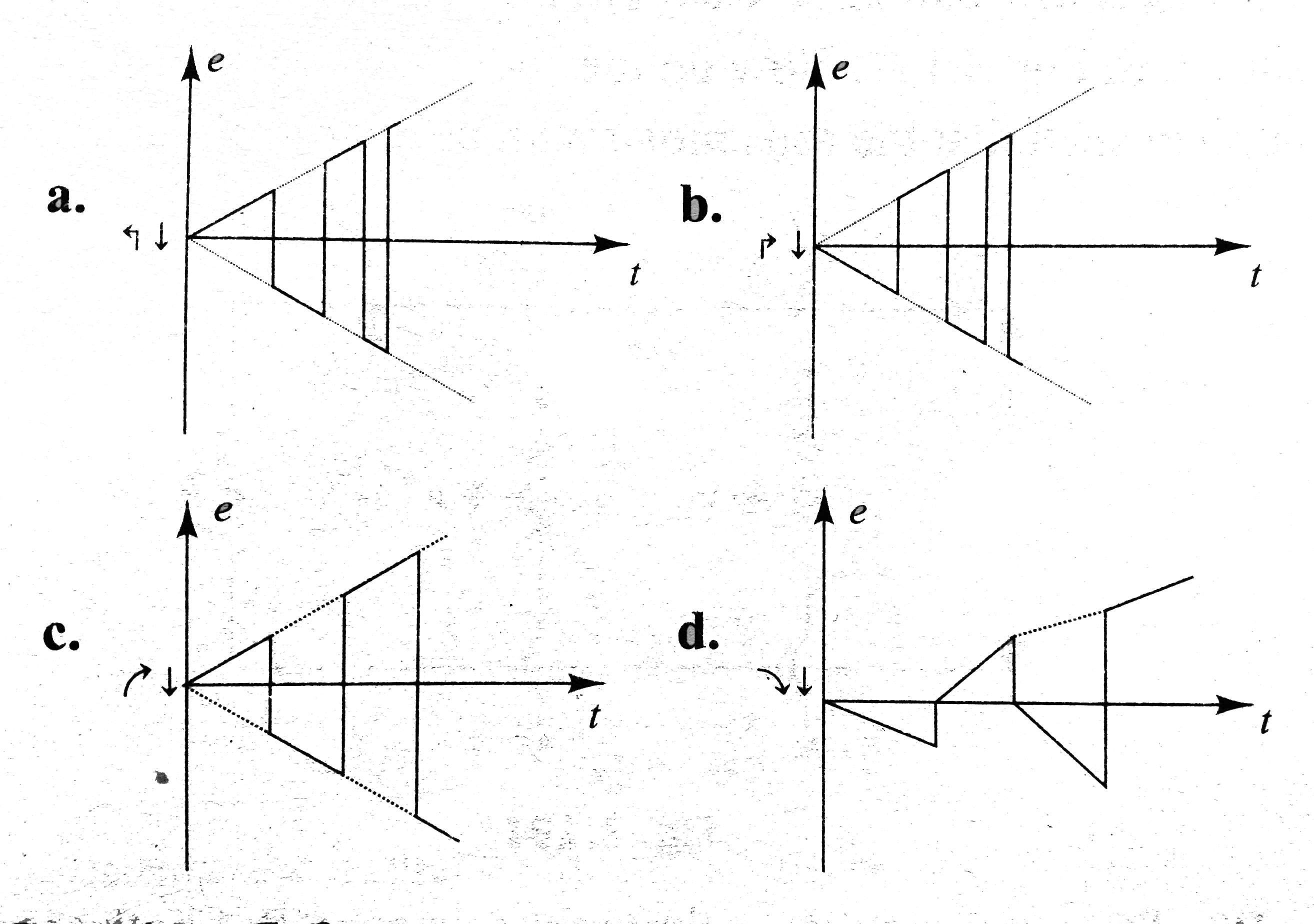
The variation of emf as a function of time is View SolutionQuestion 67
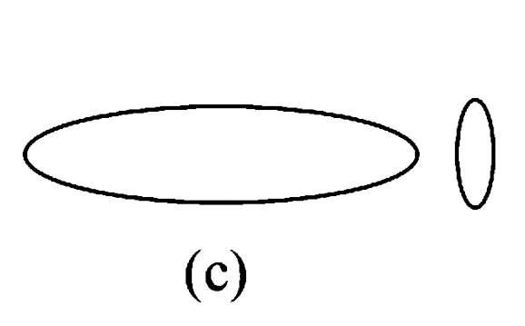
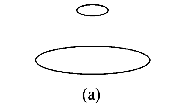
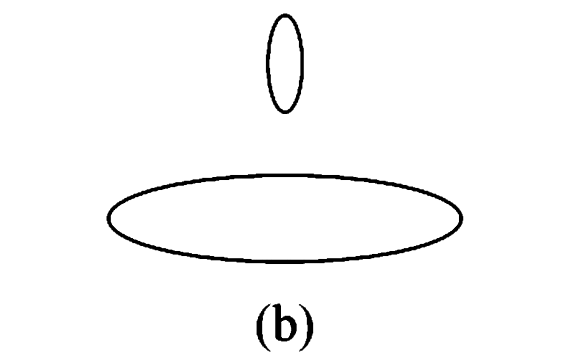
Figure. shows two parallel and coaxial loops. The smaller loop (radius r) is above the larger loop (radius R), by distance x>>R. The magnetic field due to current i in the larger loop is nearly constant throughout the smaller loop. Suppose that x is increasing at a constant rate of dx/dt=v.
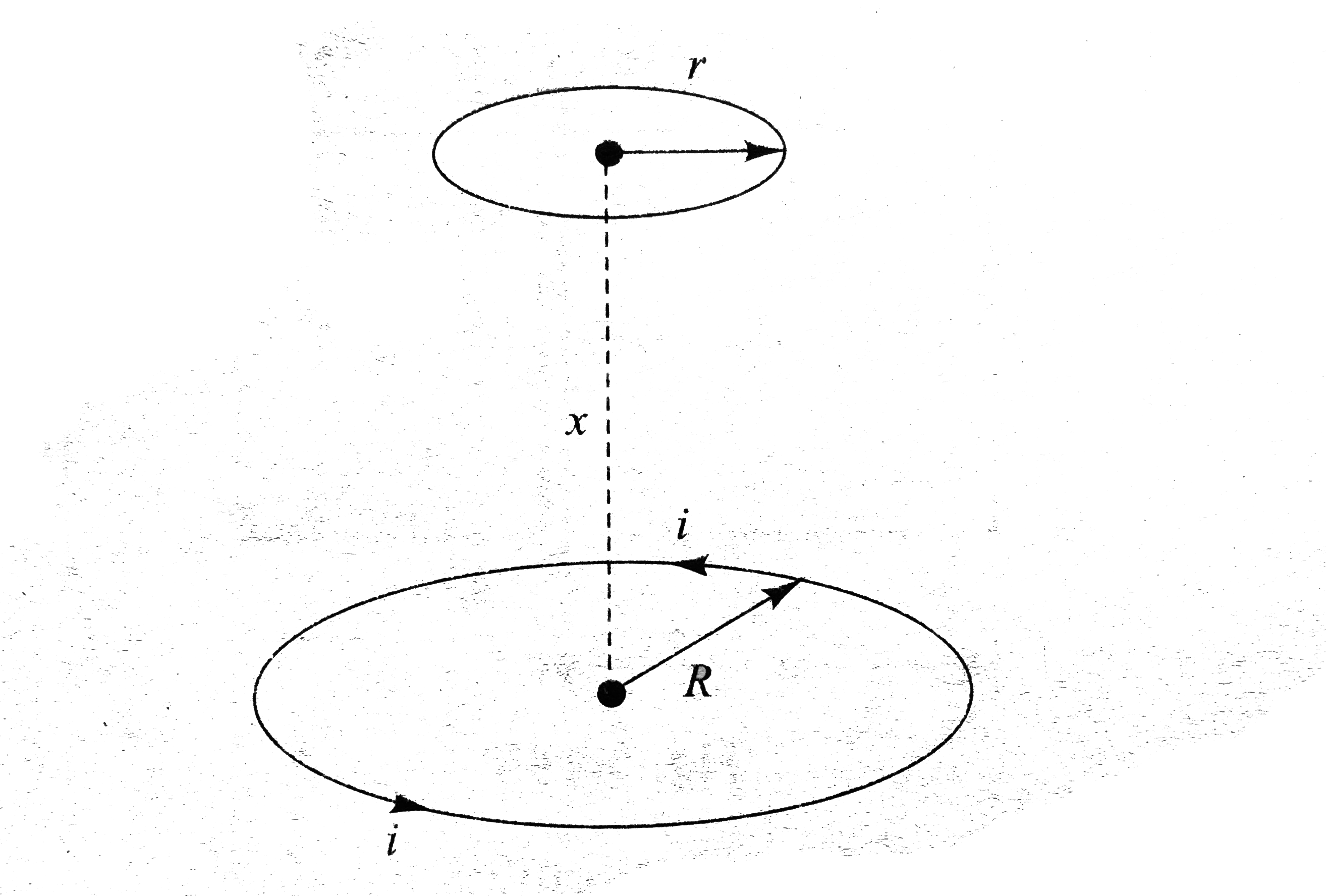
Determine the magnetic flux through the smaller loop as a function of x. View SolutionQuestion 68
Figure 3.188 shows two parallel and coaxial loops. The smaller loop (radius r) is above the larger loop (radius R), by distance x>>R. The magnetic field due to current i in the larger loop is nearly constant throughout the smaller loop. Suppose that x is increasing at a constant rate of dx/dt=v.
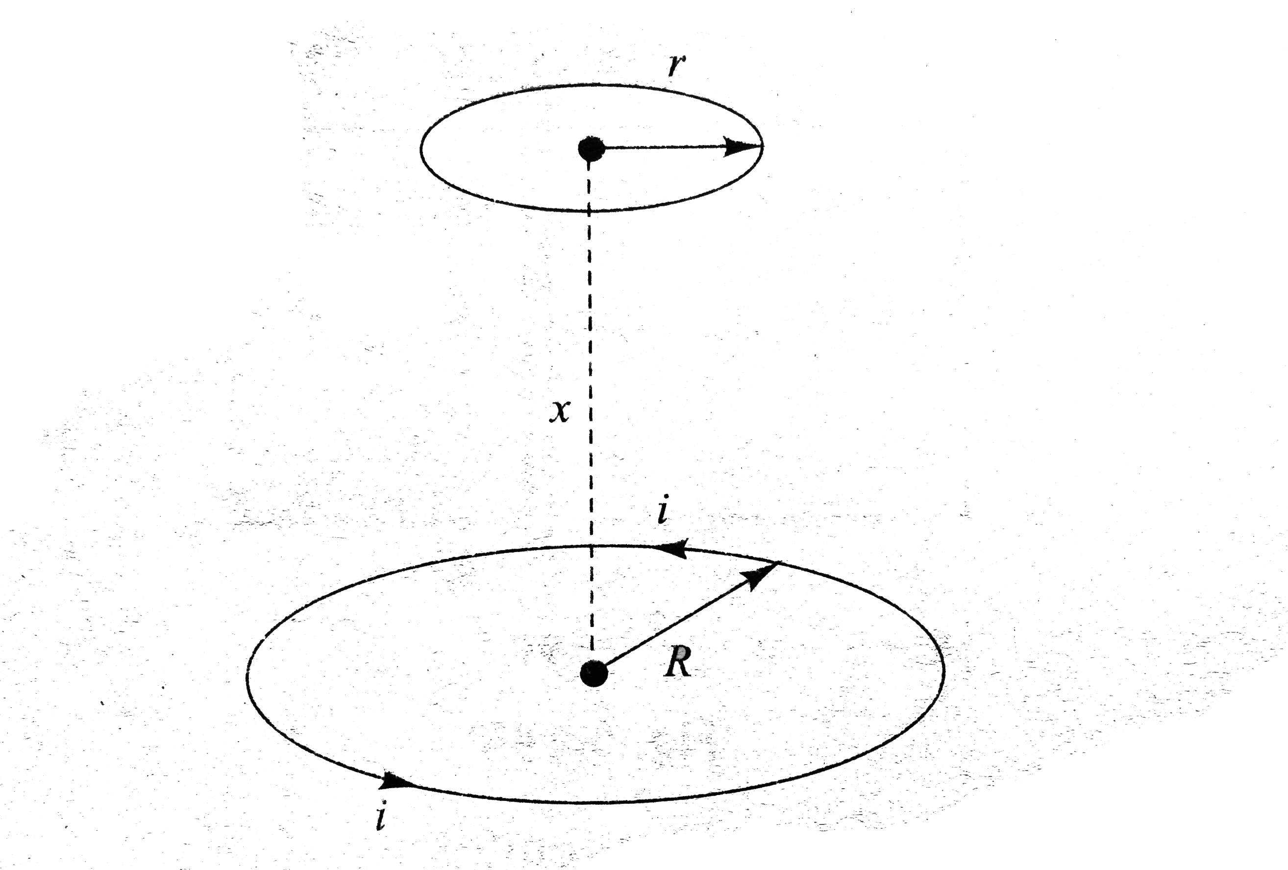
The induced emf in the smaller loop is View SolutionQuestion 69
In a conventional vehicle, power is dissipated due to friction . To reduce the loss of power due to friction MAGLEV train using an LEDS (electrodynamic suspension) technology was developed. It works on the principle of Lenz's law. In this system, a train moves without contact with the track due to which there is no loss of power due to friction.
The advantage of EDS is thatView SolutionQuestion 70
In a conventional vehicle, power is dissipated due to friction . To reduce the loss of power due to friction MAGLEY train using an EDS (electrodynamic suspension) technology was developed. It works on the principle of Lenz's law. In this system, a train moves without contact with the track due to which there is no loss of power due to friction.
Which of the following statements about MAGLEV train is correct?View SolutionQuestion 71
In a conventional vehicle, power is dissipated due to friction . To reduce the loss of power due to friction MAGLEV train using an LEDS (electrodynamic suspension) technology was developed. It works on the principle of Lenz's law. In this system, a train moves without contact with the track due to which there is no loss of power due to friction.
The disadvantage of LEDS is thatView SolutionQuestion 75
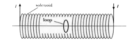
A 0.100 m long solenoid has a radius of 0.050 m and 1.50×10⁴ turns. The current in the solenoid changes at a rate of 6.0 A/s. A conducting loop of radius 0.0200 m is placed at the center of the solenoid with its axis the same as that of the solenoid as shown.

What is the magnetic flux through the small loop when the current through the solenoid is 2.50 A?View SolutionQuestion 76
A 0.100 m long solenoid has a radius of 0.050 m and 1.50×10⁴ turns. The current in the solenoid changes at a rate of 6.0 A/s. A conducting loop of radius 0.0200 m is placed at the center of the solenoid with its axis the same as that of the solenoid as shown.
Determine the mutual inductance of this combination.View SolutionQuestion 77
A 0.100 m long solenoid has a radius of 0.050 m and 1.50×10⁴ turns. The current in the solenoid changes at a rate of 6.0 A/s. A conducting loop of radius 0.0200 m is placed at the center of the solenoid with its axis the same as that of the solenoid as shown.

Determine the induced emf in the loop.View SolutionQuestion 78
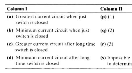
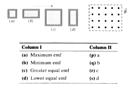
The following figure shows four wire loops, with edge lengths of either Lor 2L. All four loops will move through a region of uniform magnetic field B (directed out of the page) at the same constant velocity. (Corresponding to loop mentioned in Column II, information on induced emf is provided in Column I, match them correctly).
 View Solution
Question 80
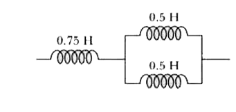
In each question, there is a table having 3 columns and 4 rows. Based on the table, there are 3 questions. Each question has 4 options (a), (b), (c) and (d), ONLY ONE of these four options is correct.
In the given table Column I lists the elements in the circuit, Column II shows their combination and Column III shows the circuit diagram.
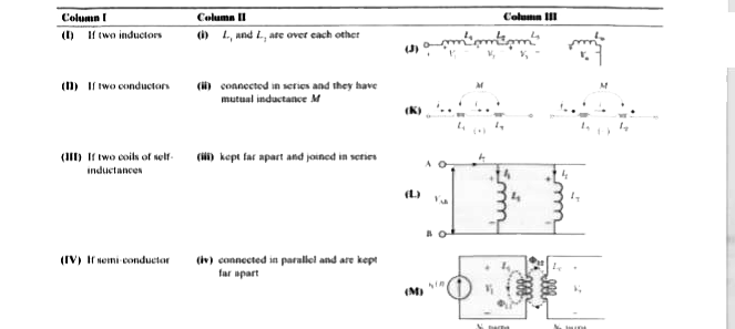
What are the conditions for L=L1+L2?View SolutionQuestion 81
In each question, there is a table having 3 columns and 4 rows. Based on the table, there are 3 questions. Each question has 4 options (a), (b), (c) and (d), ONLY ONE of these four options is correct.
In the given table Column I lists the elements in the circuit, Column II shows their combination and Column III shows the circuit diagram.
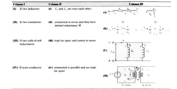
What are the conditions for 1/L=1/L1+1/L2?View SolutionQuestion 82
In each question, there is a table having 3 columns and 4 rows. Based on the table, there are 3 questions. Each question has 4 options (a), (b), (c) and (d), ONLY ONE of these four options is correct.
In the given table Column I lists the elements in the circuit, Column II shows their combination and Column III shows the circuit diagram.
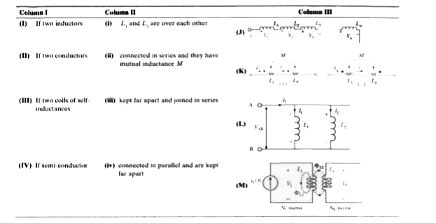
What are the conditions for M =K√L1L2?View SolutionQuestion 83
Let magnetic flux be ϕB , induced emf be ξ and power P. All the three quantities related with each other, that is, if we vary the magnetic flux, induced emf and power change according the variation of magnetic flux. In the given table, Column I shows the variation of magnetic flux, Column II shows the effect on induced emf and Column III shows the effect on power.
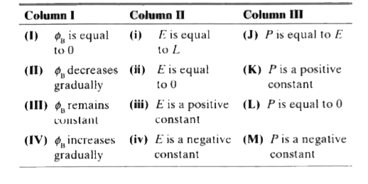
What are the conditions for a coil entering the magnetic field?View SolutionQuestion 84
Let magnetic flux be ϕB , induced emf be ξ and power P. All the three quantities related with each other, that is, if we vary the magnetic flux, induced emf and power change according the variation of magnetic flux. In the given table, Column I shows the variation of magnetic flux, Column II shows the effect on induced emf and Column III shows the effect on power.
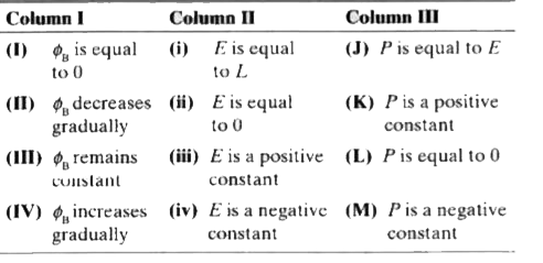
What are the conditions for a coil moving in the magnetic field?View SolutionQuestion 85
Let magnetic flux be ϕB , induced emf be ξ and power P. All the three quantities related with each other, that is, if we vary the magnetic flux, induced emf and power change according the variation of magnetic flux. In the given table, Column I shows the variation of magnetic flux, Column II shows the effect on induced emf and Column III shows the effect on power.
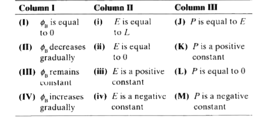
What are the conditions for a coil out of the field?View SolutionQuestion 91
The two rails of a railway track insulated from each other and the ground are connected to a millivoltmeter. What will be the reading of the millivoltmeter, when a train travels at a speed of 180 km/h along the track? Given that the vertical component of Earth's field is 2×10⁻⁵Wb/m2 and the rails are separated by 1 m.View SolutionQuestion 99
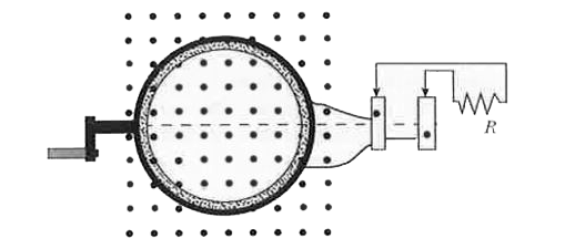
An a.c. generator consists of a coil of 50 turns and area 2.5m2 rotating att an angular speed of 60rads−1 in a uniform magnetic field B = 0.3 T between two fixed pole pieces. The resistance of the circuit including that of coil is 500Ω. Find (i) the max. current drawn from the generator.
(ii) What will be the orientaiton of the coil w.r.t. the magnetic field to have (a) maximum (b) zero magnetic flux ?
(iii) Would the generator work if the coil were stationary and instead, the pole pieces rotated together with the same speed as above ?View Solution


 ,
,  ,
, 