Determine Thevenin’s equivalent circuit which may be used to represent the given network Fig. at the terminals AB.
The given circuit of Fig. would be solved by applying Thevenin’s theorem twice first to the circuit to the left of point C and D and then to the left of points A and B. Using this technique the network to the left of CD [Fig.] can be replaced by a source of voltage V1 and series resistance Ri1 as shown in Fig. .V1 = 12 x 6/6 + 1 + 1 = 9 volt and Ri1 = 6 x 2/6 + 2 = 1.5ΩSimilarly the circuit of Fig. reduced to that shown in Fig.V2 = 9 x 6/6 + 2 + 1.5 = 5.68 volt and Ri2 = 6 x 3.5/9.5 = 2.21
Related Solutions
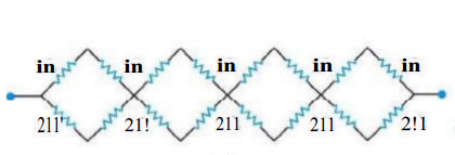
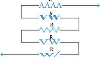
Determine the equivalent resistance of networks shown in Fig. 3.31. :
 View Solution
Determine the equivalent resistance of networks shown in Fig.
 View Solution
Determine the equivalent resistance of networks shown in Fig. (i) and (ii).
 View Solution
Determine the current in branches AB and BC of the network shown in Fig.
View SolutionThe equivalent resistance across AB in the given network is
View SolutionThe equivalent resistance across AB in the given network is
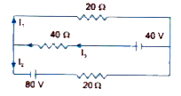
View SolutionState Kirchhoff's rules of current distribution in an electrical network. Using these rules determine the value of the current in the electric circuit of Fig.
 View Solution
State Kirchhoff's rules of current distribution in an electrical network. Using these rules determine the value of the current in the electric circuit of Fig.
 View Solution
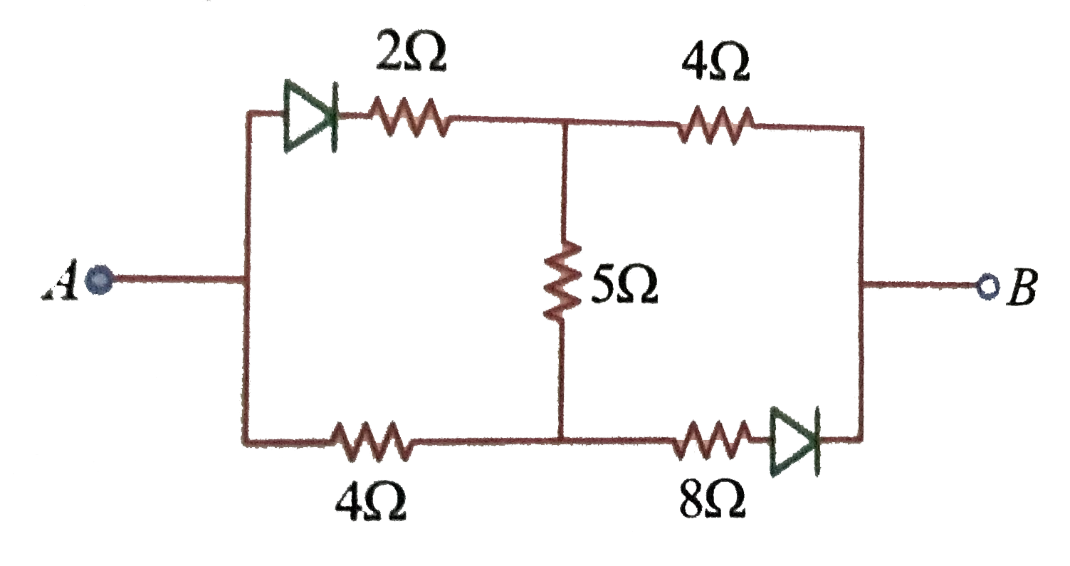
The equivalent resistane of the given circuit between the terminals A and B is :
View SolutionCalculate the voltage across AB terminals in the given circuit ,
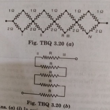
View SolutionDetermine the equivalent resistance of the following networks:
 View Solution
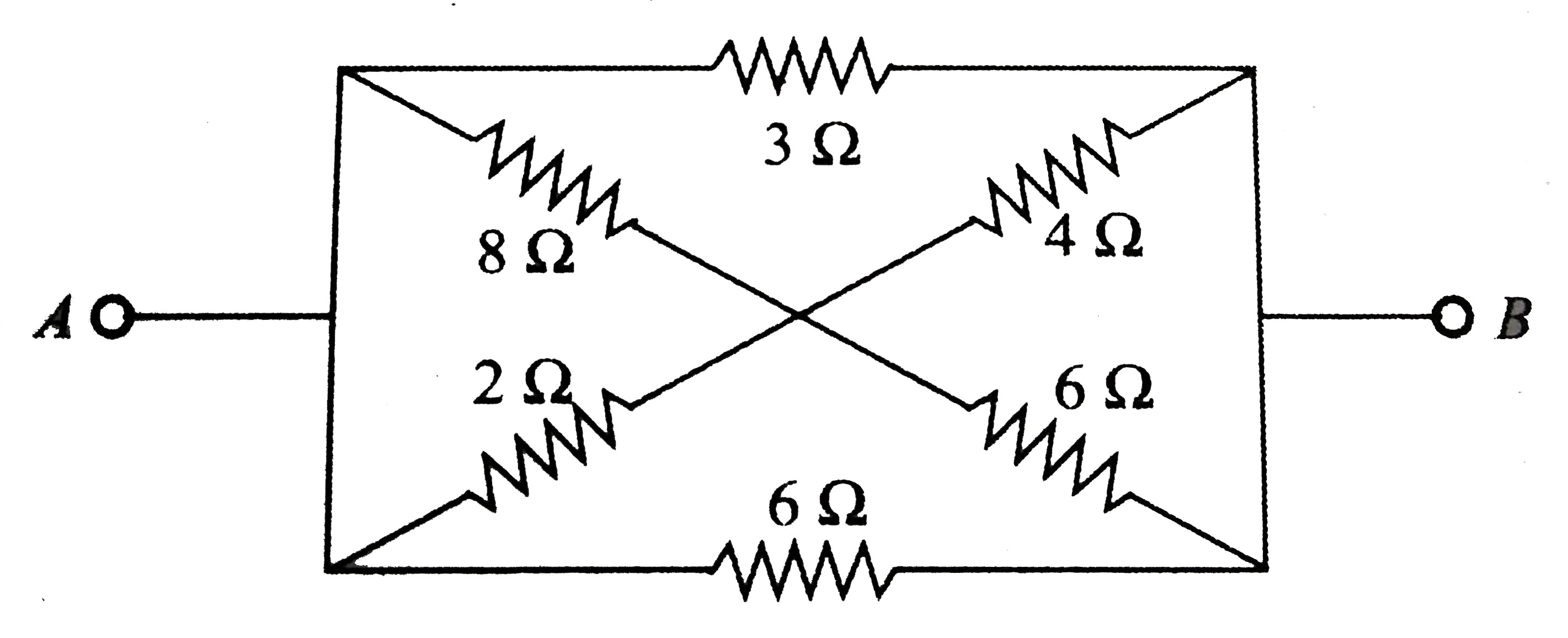
The equivalent resistance between A and B in the network in fig.,
 View Solution
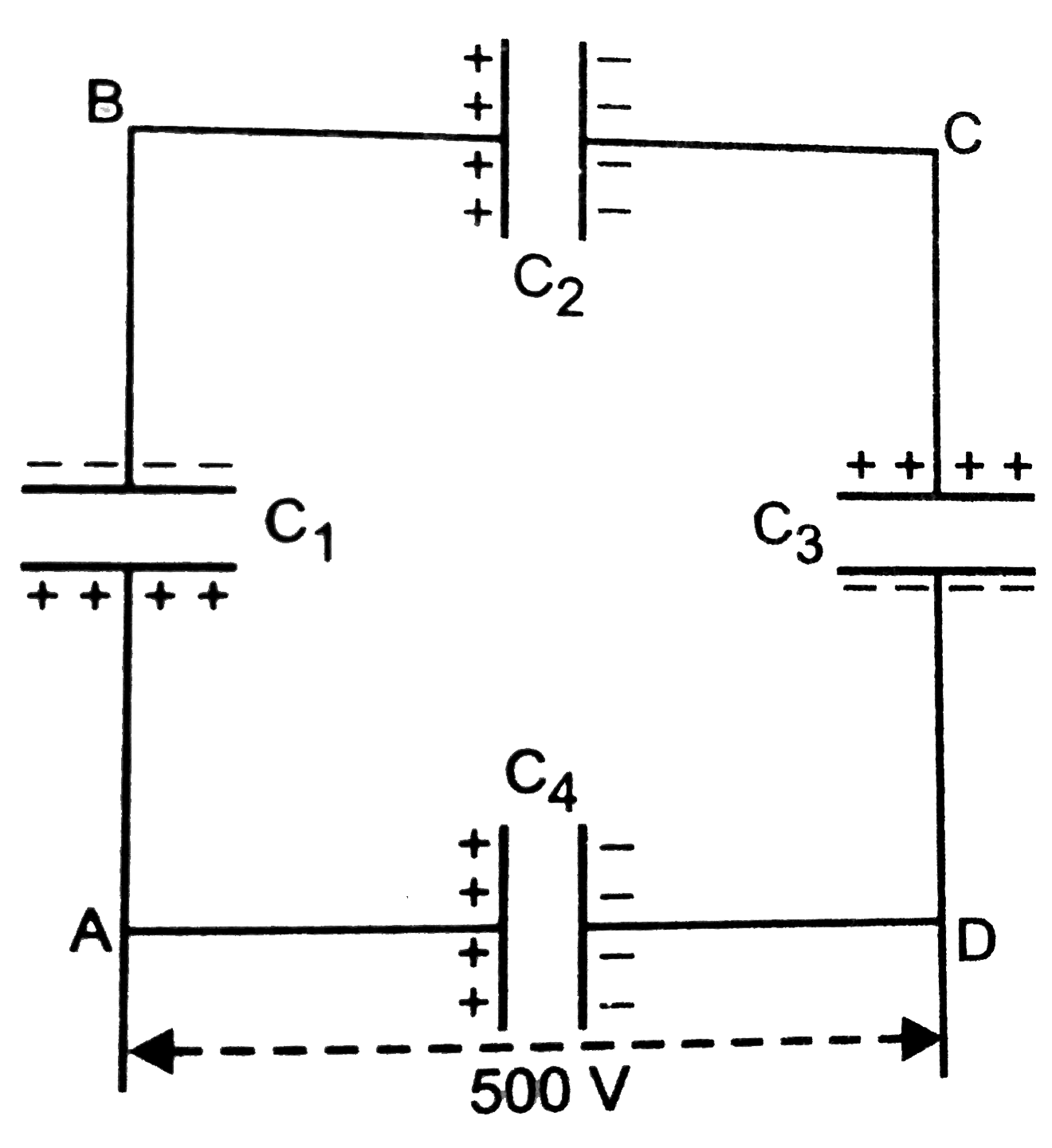
A network of four capacitors each of 12 capacitance is connected to a 500 V supply as shown in the Fig .
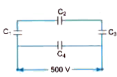
Determine equivalent capacitance of the network .View SolutionA network of four capacitors is connected to a 500V supply as shown in Fig. Determine the (a) equivalent capacitance of the network and (b) charge on each capacitor.
 View Solution
दिया गया विघुत नेटवर्क किस गेट के तुल्य है ?
 View Solution
दिया गया विघुत नेटवर्क किस गेट के तुल्य है ?
 View Solution
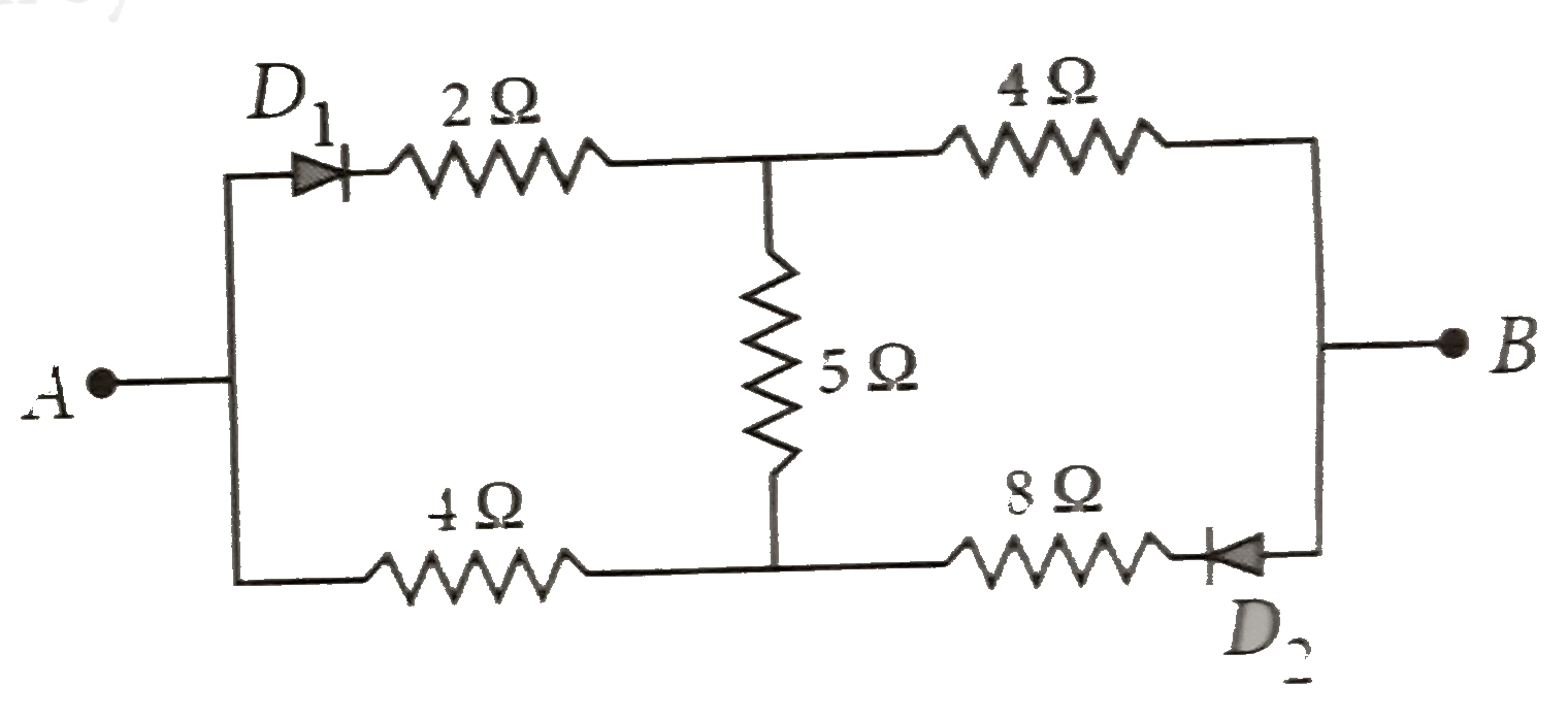
The equivalent resistance of the circuit, across AB is given by
 View Solution
The equivalent resistance of the circuit across is given by
 .View Solution
The equivalent resistance of the circuit across AB is given by .
View SolutionThe equivalent resistance of the circuit, across AB is given by
 View Solution
