Determine the internal forces that occur in the plane pin-jointed truss of Figure a due to the externally applied vertical load of 3 kN.
Firstly we will fill the spaces between the forces with upper case letters of the alphabet as shown in figurea. It should be noted that the only reactions are the vertical reactions R1 and R2; this is because the only externally applied load is the vertical load of 3 kN and there is no external horizontal load. The capital letters A B C and D can be used to represent the forces between them providing they are taken in a clockwise direction about each joint. Thus the letters AB represent the vertical load of 3 kN. Now as this load acts vertically downwards it can be represented by a vector ab where the magnitude of ab is 3 kN and it points in the direction from a to b. As ab is a vector it will have a direction as well as a magnitude. Thus ab will point downwards from a to b as the 3 kN load acts downwards.This method of representing forces is known as Bow’s notation.To analyse the truss we must first consider the joint ABD; this is because this joint has only two unknown forces namely the internal forces in the two members that meet at the joint ABD. Neither joints BCD and CAD can be considered first because each of these joints has more than two unknown forces.Now the 3 kN load is between the spaces A and B so that it can be represented by the lower case letters ab point from a to b and of magnitude 3 kN as shown in Figure b.Similarly the force in the truss between the spaces B and D namely the vector bd lies at 60° to the horizontal and the force in the truss between the spaces D and A namely the vector da lies at 30° to the horizontal. Thus in Figure b if the vectors bd and ad are drawn they will cross at the point d where the point d will obviously lie to the left of the vector ab as shown. Hence if the vector ab is drawn to scale the magnitudes of the vectors bd and da can be measured from the scaled drawing. The direction of the force in the member between the spaces B and D at the joint ABD point upwards because the vector from b to d points upwards. Similarly the direction of the force in the member between the spaces D and A at the joint ABD is also upwards because the vector from d to a points upwards. These directions at the joint ABD are shown in Figurec. Now as the framework is in equilibrium the internal forces in the members BD and DA at the joints 2 and 1 respectively will be equal and opposite to the internal forces at the joint ABD; these are shown in Figure c. Comparing the directions of the arrows in Figure c with those of Figure h it can be seen that the members BD and DA are in compression and are defined as struts. It should also be noted from Figure c that when a member of the framework say BD is so defined we are referring to the top joint because we must always work around a joint in a clockwise manner; thus the arrow at the top of BD points upwards because in Figure b the vector bd points upwards from b to d. Similarly if the same member is referred to as DB then we are referring to the bottom of this member at the joint 2 because we must always work clockwise around a joint. Hence at joint 2 the arrow points downwards because the vector db points downwards from d to b in Figure b.To determine the unknown forces in the horizontal member between joints 1 and 2 either of these joints can be considered as both joints now only have two unknown forces. Let us consider joint 1 i.e. joint ADC. Now the vector ad can be measured from Figure band drawn to scale in Figure d.Now the unknown force between the spaces D and C namely the vector dc is horizontal and the unknown force between the spaces C and A namely the vector ca is vertical hence by drawing to scale and direction the point c can be found. This is because the point c in Figure d lies below the point a and to the right of d.In Figure d the vector ca represents the magnitude and direction of the unknown reaction R1 and the vector dc represents the magnitude and direction of the force in the horizontal member at joint 1; these forces are shown in Figure e where R1 = 0.82 kN and dc = 1.25 kN. Comparing the directions of the internal forces in the bottom of the horizontal member with Figure h it can be seen that this member is in tension and therefore it is a tie.The reaction R2 can be determined by considering joint 2 i.e. joint BCD as shown in Figure f where the vector bc represents the unknown reaction R2 which is measured as 2.18 kN.The complete vector diagram for the whole framework is shown in Figure g where it can be seen that R1 + R2 = 3 kN as required by the laws of equilibrium. It can also be seen that Figure g is a combination of the vector diagrams of Figures b d and f. Experience will enable this problem to be solved more quickly by producing the vector diagram of Figure g directly The table below contains a summary of all the measured forces.
Related Solutions
यदि PN सन्धि के परितः कोई बाह्य वोल्टेज न लगाया जाये तो
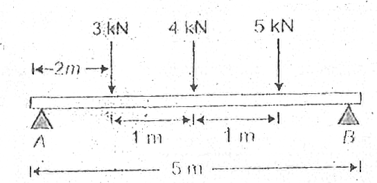
View SolutionA massless beam of langth 5 m is placed on two wedges A and B. If three forces 3 kN, 4 kN and 5 kN are applied on the beam as shown in the figure, then find normal reaction at A and B.
 View Solution
A massless beam of langth 5 m is placed on two wedges A and B. If three forces 3 kN, 4 kN and 5 kN are applied on the beam as shown in the figure, then find normal reaction at A and B.
View Solutionक्या बाह्य बल के प्रभाव से पिंड की गति में आतंरिक बलों का योगदान होता है ?
View Solutionजब कोई बाहा बल न लगा हो तब द्रव की छोटी बून्द की आकृति निर्धारित होती है -
View Solutionबाह्य श्वसन ____________ में होता है और आंतरिक श्वसन _______ में होता है।
View SolutionExternal respiration occurs in the ________________ and internal respiration occurs in the ___________________
View SolutionExternal respiration occurs in the ________________ and internal respiration occurs in the ___________________
View SolutionWhat is internal force and external force?
View SolutionIf a force of 1 kN is applied to a 10 kg object, what will be the acceleration?
View SolutionWhat is meant by an internal force & external force ?
View SolutionDistinguish between internal and external forces.
View SolutionA wire loop carrying a current I is placed in the xy-plane as shown in figure If an external uniform magnetic induction field B=Bhati is applied, find the force acting on the loop due to this field.
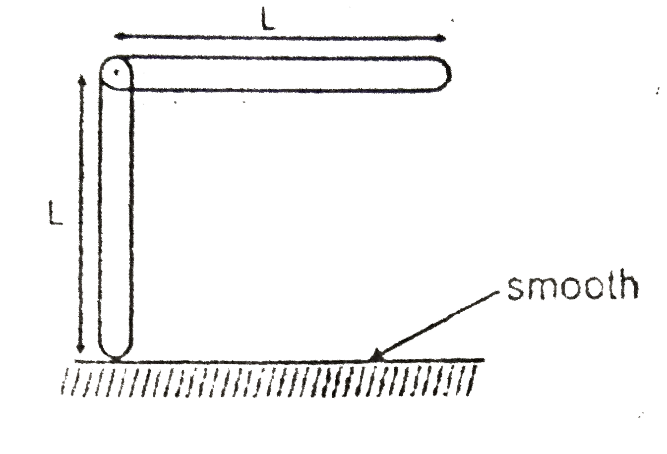
View SolutionTwo identical rods are joined at one of their ends by a pin. Joint is smooth and rods are free to rotate about the joint. Rods are released in vertical plane on a smooth surface as shown in the figure. The displacement of the joint from its initial position to the final position is (i.e. when the rods lie straight on the groun )
View SolutionTwo identical rods are joined at one of their ends by a pin. Joint is smooth and rods are free to rotate about the joint. Rods are released in vertical plane on a smooth surface as shown in the figure. The displacement of the joint from its initial position to the final position is when the rods lie straight on the groun
 View Solution
A load is uniformly moved over a horizontal plane by a force F applied at an angle to the horizontal. Find this force if the coefficient of friction between the load and the plane is 0.3. Take
View SolutionNodding movement of head occurs due to the joint between
View SolutionNodding movement of head occurs due to the joint between
View SolutionThe movement occuring due to external stimulus is
View SolutionIn movement occurs due to external stimulus
View Solution
