Using any suitable method calculate the current through 4 ohm resistance of the network shown in Fig..
We will solve this question with the help of i Kirchhoff’s laws ii Mesh analysis and iii Nodal analysis. i Solution by using Kirchhoff’s Laws Let the current distribution be as shown in Fig. . Using the same sign convention as given in we have First Loop − 10I1 + I2 + I3 − −j5 I1 + 100 = 0 or I1 10 −j5 + 10I3 + 10I2 = 100 ...i Second Loop −5I2 + I3 − 4I2 + −j5 I1 = 0 or j5I1 + 9I2 + 5I3 = 0 ...ii Third Loop −I3 8 + j6 + 4I2 = 0 or 0I1 + 4I2 −I3 8 + j6 = 0 ...iii The matrix form of the above three equations isΔ = 10 −j 5 [−9 8 + j 6 − 20] −j 5 [−108 + j 6 − 40] = − 1490 + j 520 = 1578∠160.8º Since we are interested in finding I2 only we will calculate the value of Δ2.ii Solution by using Mesh Impedance MatrixLet the mesh currents I1 I2 and I3 be as shown in Fig.. From the inspection of Fig. the different items of the mesh impedance matrix [Zm] are as under : Z11 = 10 −j 5 ; Z22 = 9 −j 5; Z33 = 12 + j 6 Z21 = Z12 = − −j 5 = j 5; Z23 = Z32 = − 4;Z31 = Z13 = 0 Hence the mesh equations in the matrix form are :∴ Δ = 10 −j 5 [9 −j 5 12 + j 6−16] −j5 j 60 − 30 = 1490 - j 520 = 1578∠19.2º It should be noted that the current passing through 4 Ω resistance is the vector diference I2 −I3. Hence we will find I2 and I3 only.I3 = Δ3/Δ = 200 ∠-90º/1578 ∠- 19.2º= 1.27 ∠ − 70.8º = 0.42 −j 1.2Current I2 −I3 = 2.63 − j 1.76 = 3.17 ∠− 33.9º iii Solution by Nodal Analysis The current passing through 4 Ω resistance can be found by finding the voltage VB of node B with the help of Nodal analysis. For this purpose point C in has been taken as the reference node. Using the Nodal technique as explained in . we haveVA1/10 + 1/5 + 1/-j5 - Vb/5 - 100∠ 0º/10 = 0 for node A VA 3 + j 2 − 2 VB = 100 ...i Similarly for node B we haveVB1/5 + 1/4 + 1/8 + j6 - VA/5 = 0or VB53 −j 6 − 20 VA = 0 ...ii Estimating VA from Eq. i and ii we have VB131 + j88 = 2000 or VB = 12.67 ∠−33.9ºCurrent through 4 Ω resistor 12.67 ∠−33.9º/4 = 3.17 ∠−33.9º
Related Solutions
A battery of internal resistance 4 is connected to the network or resistances as shown in Fig. In order that maximum power cab be delivered to the network, the value of R in ohm should be
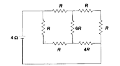
View SolutionA battery of internal resistance is connected to the network of resistances as shown in Fig. In order that maximum power can be delivered to the network, the value of R in ohm should be:
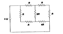
View SolutionIn the fig. shown, Calculate the current through 3 ohm resistor. The emf of battery is 2 volt and its internal resistance is ohm.
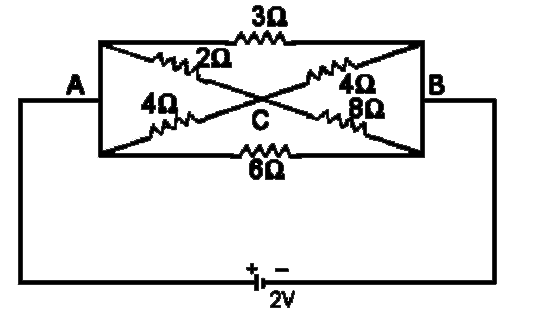
View SolutionFor the given network, find the current through 4 ohm and 3 ohm. Assume that the cells have negligible internal resistance.
View SolutionIn the electric network shown in the Fig., use Kirchhoff's rules to calculate the power consumed by the resistance
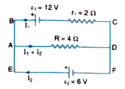
View SolutionIn the network shown calculate current through the cell and the current through the resistance.
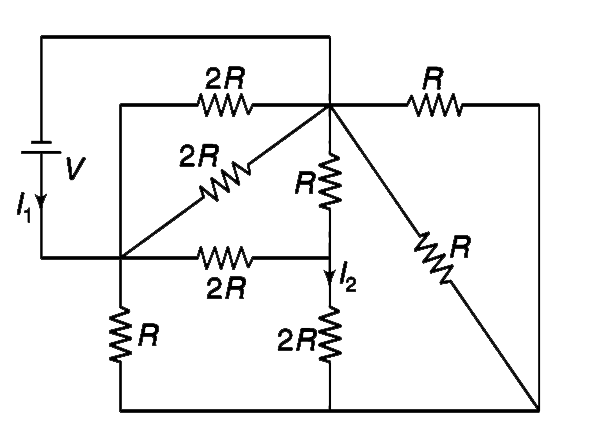
View SolutionEach resistance shown in the network is in ohm. Current through the resistor 3 Omega is 0.25 A. The input voltage 'V' is equal to
View SolutionEach resistance shown in the network is in ohm. Current through the resistor is 0.25 A. The input voltage 'V' is equal to

View SolutionCalculate the resistance between the terminals A and B of the network shown in fig

View SolutionIn the network shown in Fig., calculate the equivalent resistance between the points
A and B,
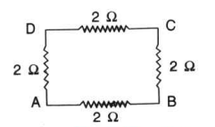
View SolutionCalculate the effective resistance between the points A and B in the network shown below in Fig.

View SolutionCalculate the resistance between the terminals A and B of the network shown in fig
View SolutionIn the network shown in Fig., calculate the equivalent resistance between the points A and C.
View Solutionचित्र में दिखाये गये वैधुत परिपथ में 4 ओम प्रतिरोध में धारा है :
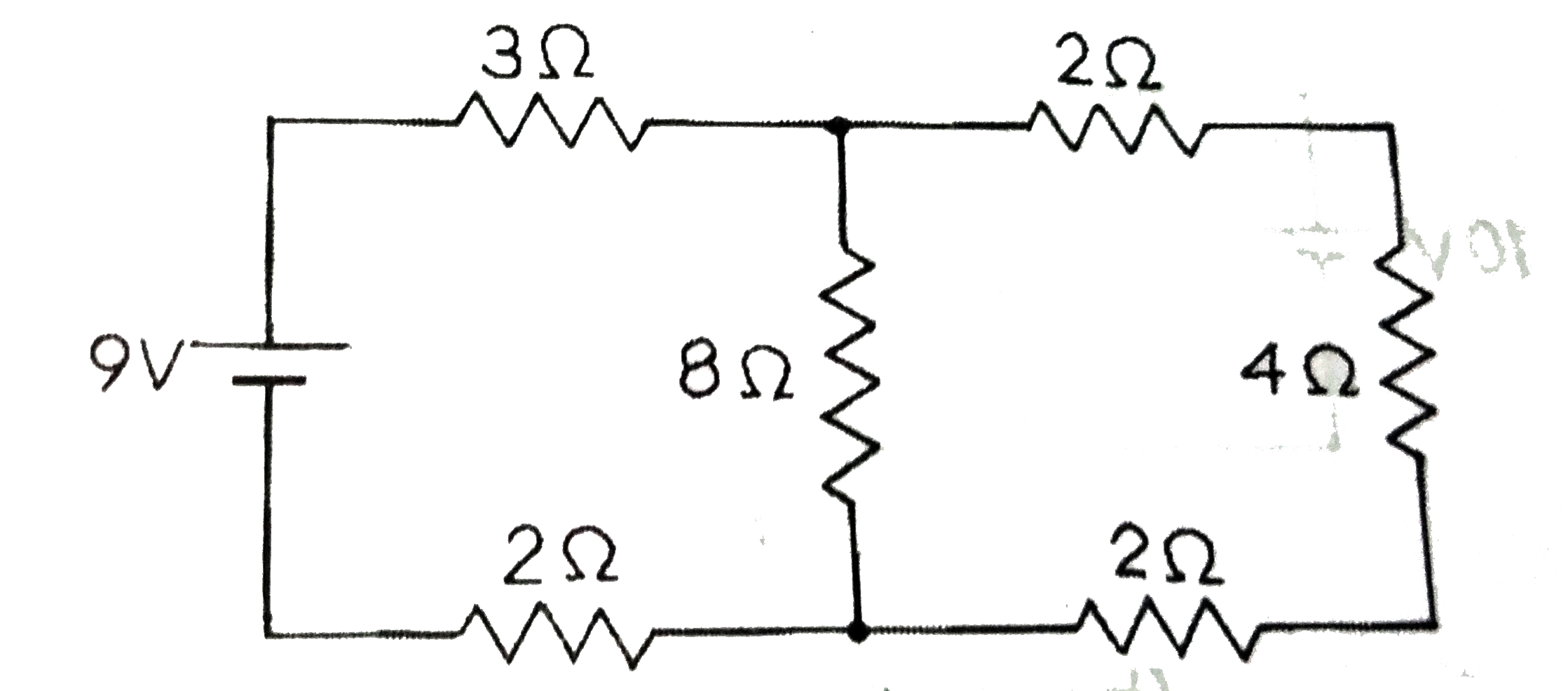
View Solutionचित्र की सहायता से 6 ओम प्रतिरोध तार में प्रवाहित धारा की गणना करें
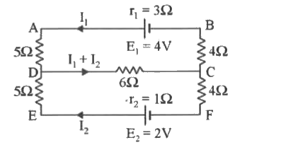
View SolutionA network of resistors is connected to a 12V battery as shown in fig.
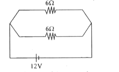
a) Calculate the equivalent resistance of the network.
b) Obtain current in and resistors.
View SolutionA broken circuit is shown in Fig. Calculate the difference at the ends of the 400 ohm resistance with a voltmeter V of 400 ohm resistance.
View SolutionDetermine the currents through the resistance of the circuits shown in fig.
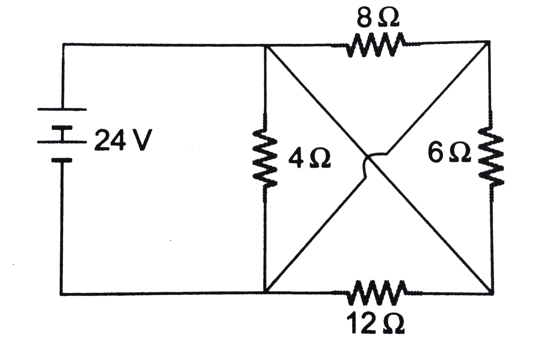
View SolutionCalculate battery current and equivalent resistance of the network shown in figure.

View SolutionCalculate battery current and equivalent resistance of the network shown in figure.
View Solution