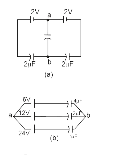
Find the potential difference Va - Vb in the circuits shown in figure 32-E12.
Related Solutions
The potential difference (VA – VB) between the points A and B in the given figure is

View SolutionFind the potential difference Va – Vb between the points a and b shows in each parts of the figure.
View SolutionIn the circuit shown in figure 3.154 find the potential difference
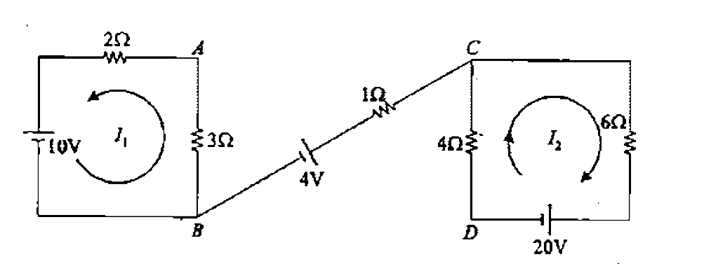
View SolutionThere is a electric circuit as shown in the figure. Find potential difference between points a and b.
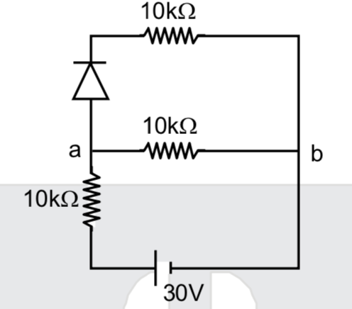
View SolutionFind the potential difference between points A and B in the circuit shown in the figure: -
View SolutionFind the potential difference V_(A)-C_(B) for the circuit shown in the figure .
View SolutionThere is a electric circuit as shown in the figure. Find potential difference between points a and b.
View SolutionPotential difference across AB in the circuit as shown in figure.

View SolutionPotential difference across AB in the circuit as shown in figure.
View SolutionIn the circuit shown in figure potential difference across
View SolutionIn the circuit shown in figure potential difference between A and B is
View SolutionIn the circuit shown in figure potential difference across
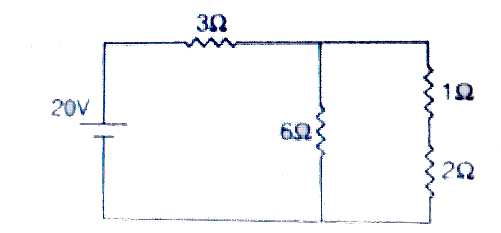
View SolutionIn the circuit shown in the Figure, find the ratio of potential difference across capacitor 1 and 2. The capacitance values are as indicated in the Figure.
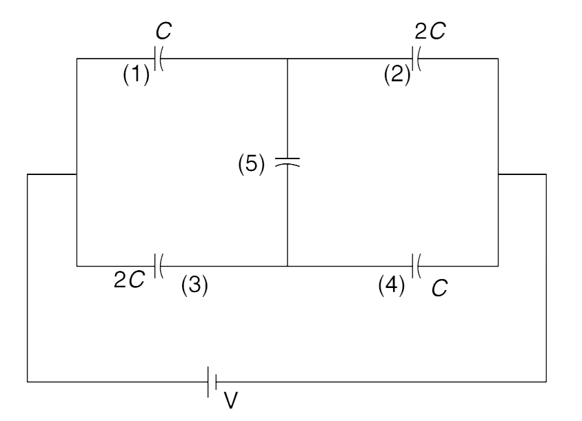
View SolutionIn the circuit shown in figure potential difference between the points and in the steady state is
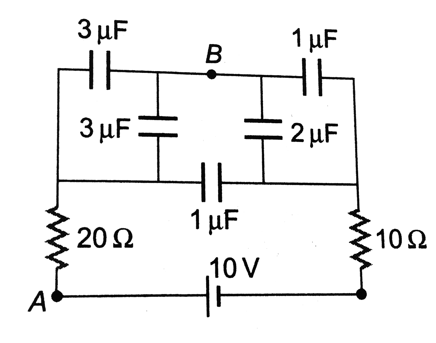
View SolutionThe potential difference between points and in the circuit shown in figure will be
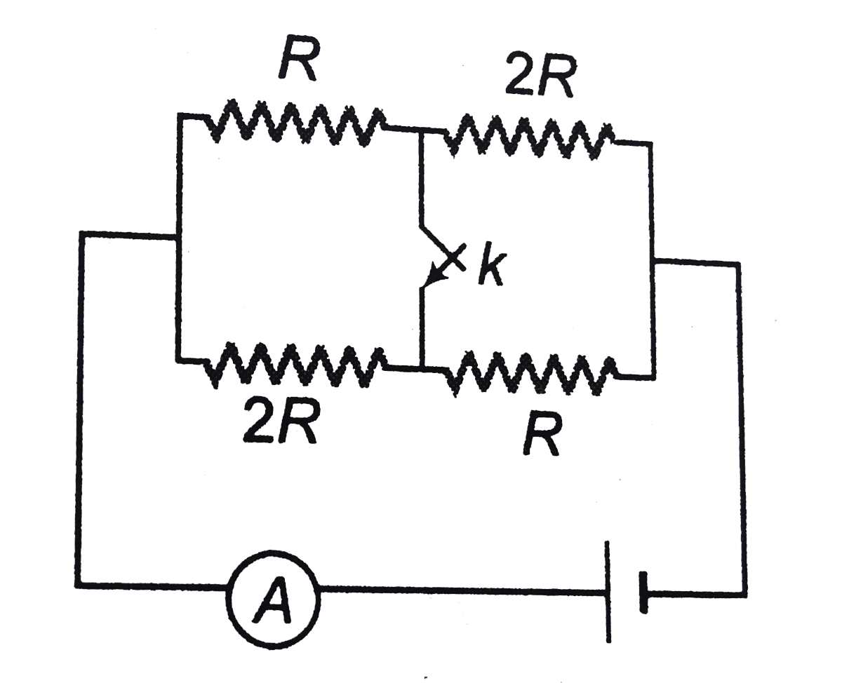
View SolutionThe potential difference between points A and Bin the circuit shown in figure-3.318, will be:
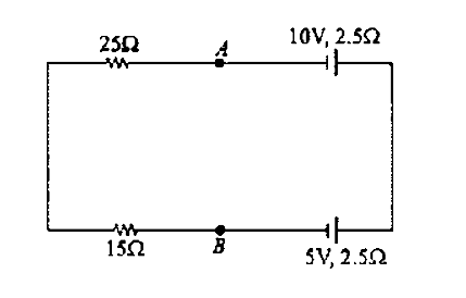
View SolutionWhat is the potential difference between the points A and B in the circuit diagram shown in figure ?
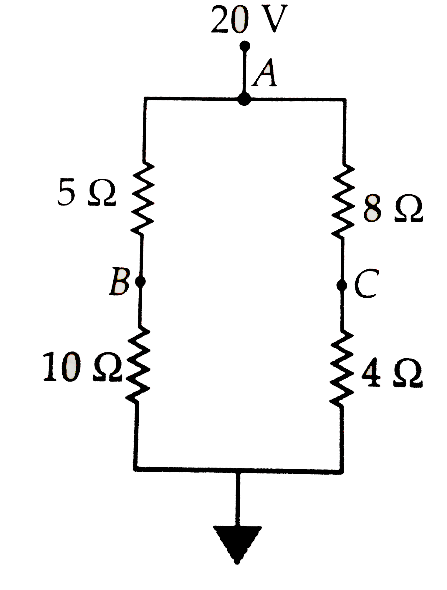
View Solution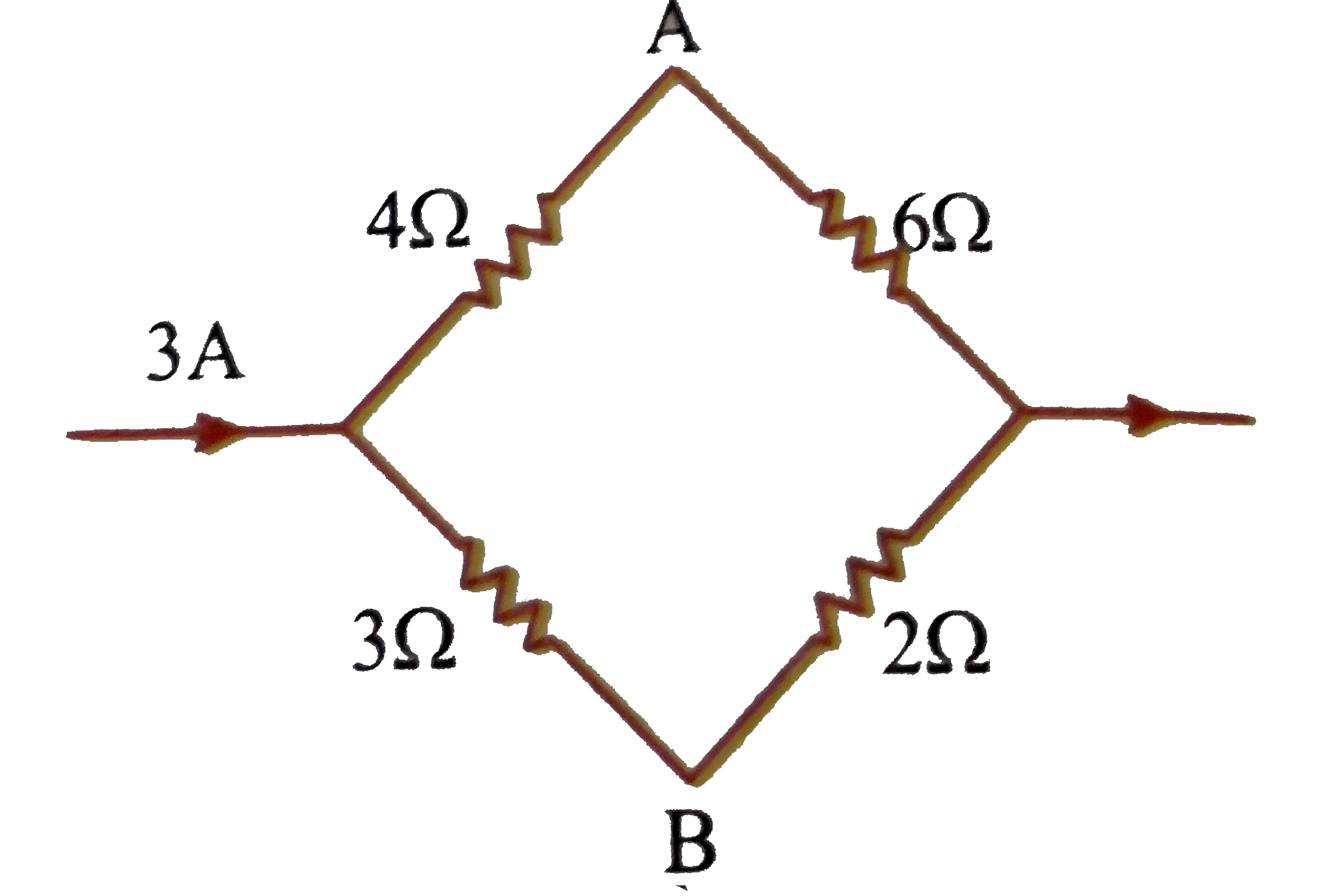
A current of 3A flows in a circuit shown in the figure. The potential difference between A and b is
View SolutionThe potential difference between points and of circuits shown in figure is
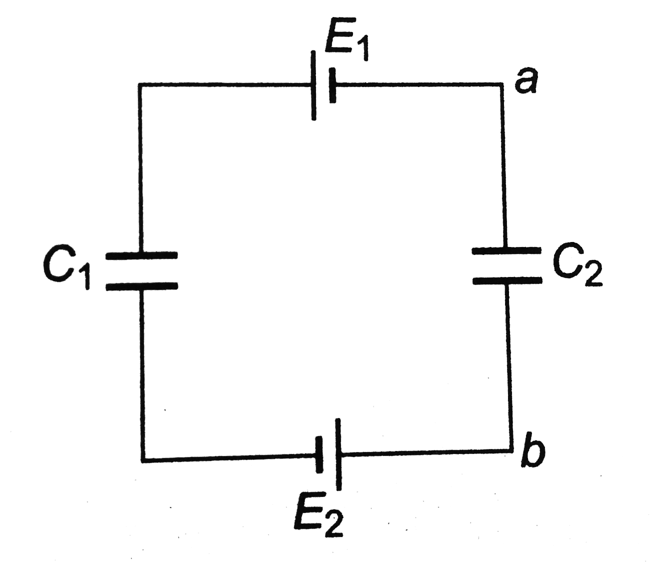
View SolutionThe potential difference between the points A and B in the following circuit shown in the figure:-
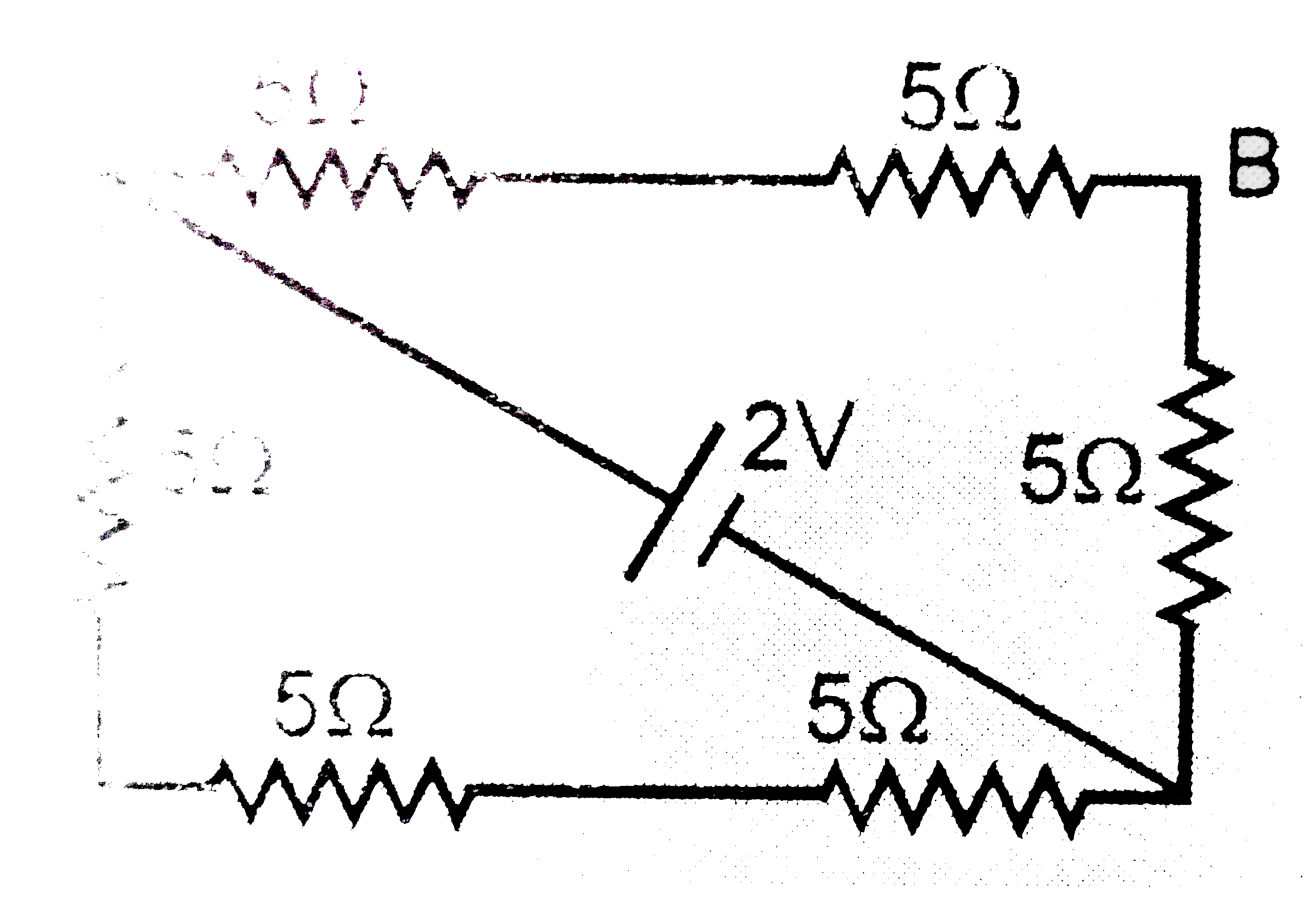
View Solution