The following diagram in Fig. 10.44 shows a coil X connected to a sensitive centre –zero galvanometer G and a coil P connected to a battery through a switch S.a Describe the observation when the switch S is i closed suddenly ii then kept closed iii finally opened.b Name and state the law which explains the above observations.
ai When switch is closed suddenly the galvanometer needle deflects for a moment.ii If switch is kept closed then galvanometer needle returns to zero.iii If switch is opened again then galvanometer needle deflects again but in opposite to the direction of deflection in case a.b This can be explained by Faradays law which states that whenever there is change in the magnetic flux linked with a coil an e.m.f. is induced. The induced e.m.f. lasts as long as there is a change in the magnetic flux linked with the coil.
Related Solutions
Two circular coils-1 and coil-2 are kept close to each other as shown in the diagram. Coil-1 is connected to a battery and key and coil-2 with a galvanometer. State your observation in the galvanometer:
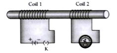
(a) When key K closed.
(b) When key K is opened, Give reason for your observations.
View SolutionA centre zero galvanometer is connected in series with a switch and a battery . When the switch is closed and opened periodically (nearly about 4 times/sec) its needle
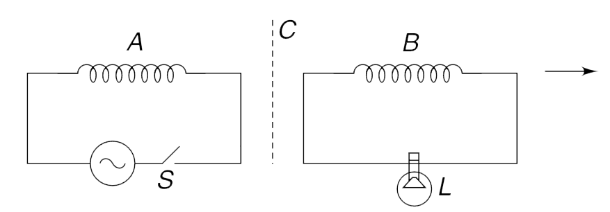
View SolutionCoil A is connected to an ac source through a switch S. Coil B, kept close to A, is connected to a low voltage bulb (L). Explain the following observations.
(i) When S is closed, the bulb lights up.
(ii) With S closed if B is moved away from A, the bulb gets dimmer.
(iii) With S closed, if a copper plate C is inserted between the coils, the bulb gets dimmer.
View SolutionTwo coils P and S are wound over the same iron core. Coil P is connected to battery and key and the coil S is connected to galvanometer. Write your observations when: (i) Current in the coil P is started by closing the key. (ii) Current continues to flow in coil P. (iii) Current in coil P is stopped by removing the key. Explain the reason for such observation.
View Solutionएक समान प्रेरक कुण्डली एवं बैटरी से जुड़े परिपथ चित्र में प्रदर्शित है (i) स्विच को बंद करने के तुरंत पश्चात (ii) स्विच को बंद करने के बहुत समय पश्चात परिपथ में बहने वाली धारा
View Solution20 ओम प्रतिरोध तथा 0.5 हेनरी प्रेरकत्व की एक कुण्डली एक परिपथ में स्विच S में होकर 200 वोल्ट बैटरी से जुडी है ज्ञात कीजिये -
(A) स्विच S बंद करते ही परिपथ में धारा वृद्धि की दर
(B) स्थायी अवस्था में परिपथ में धारा
View SolutionFig. shows three resistances are connected with a switch as shown and the switch is closed. Find the current through R_(3) resistor.
View Solutionshows three resistances are
connected with switch S initially the switch is open. When
the switch S is closed find the current passed through it.
View Solutionshows three resistances are
connected with switch S initially the switch is open. When
the switch S is closed find the current passed through it.
View SolutionThe diagram below shows a coil connected to a centre zero galvanometer G The· galvanometer shows a deflection to the right when theN-pol,e .of a powerful magnet is moved to the right as shown
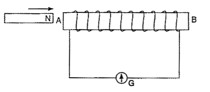
State the observation in G when, both the coil and the magnet, are moved to the right at the same speed.
View SolutionThe diagram below shows a coil connected to a centre zero galvanometer G The· galvanometer shows a deflection to the right when theN-pol,e .of a powerful magnet is moved to the right as shown State the observation in G when the coil is moved away from N.
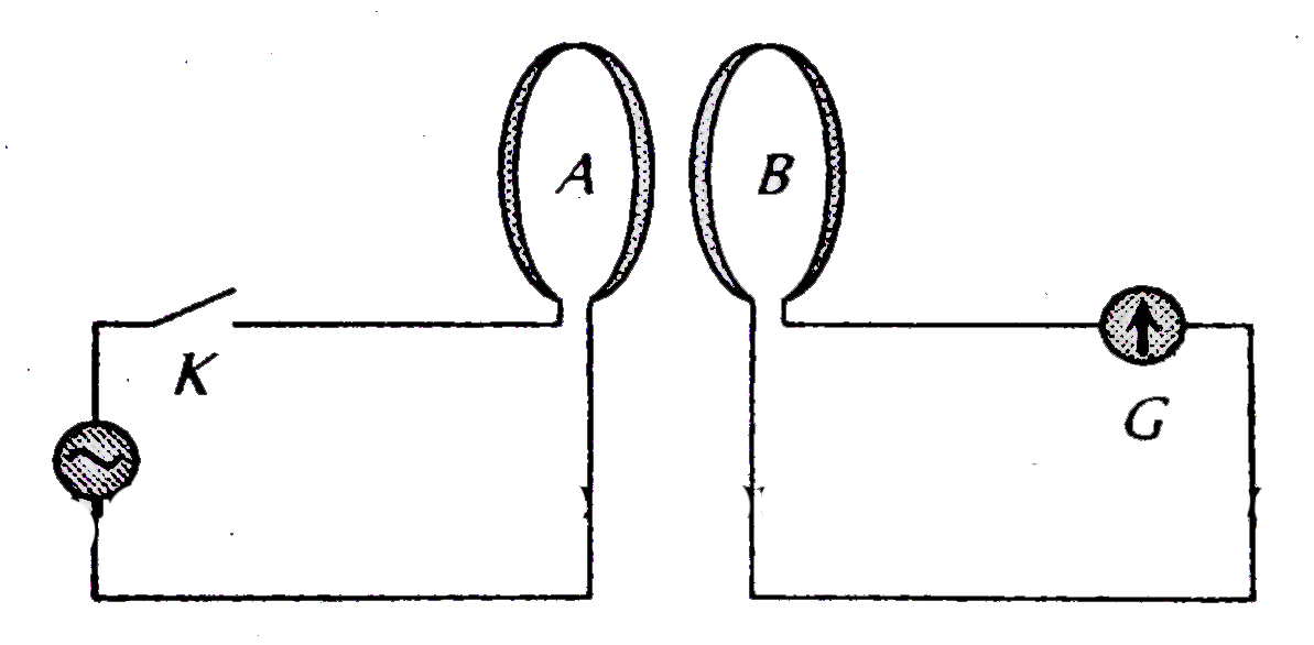
View SolutionThe diagram below shows two coils A and B placed parallel to each other at a very small distance. Coil A is connected to an ac supply. G is a very sensitive galvanometer. When the key is closed
View SolutionThe diagram below shows two coils A and B placed parallel to each other at a very small distance. Coil A is connected to an AC supply. G is a very sensitive galvanometer. When the key is closed
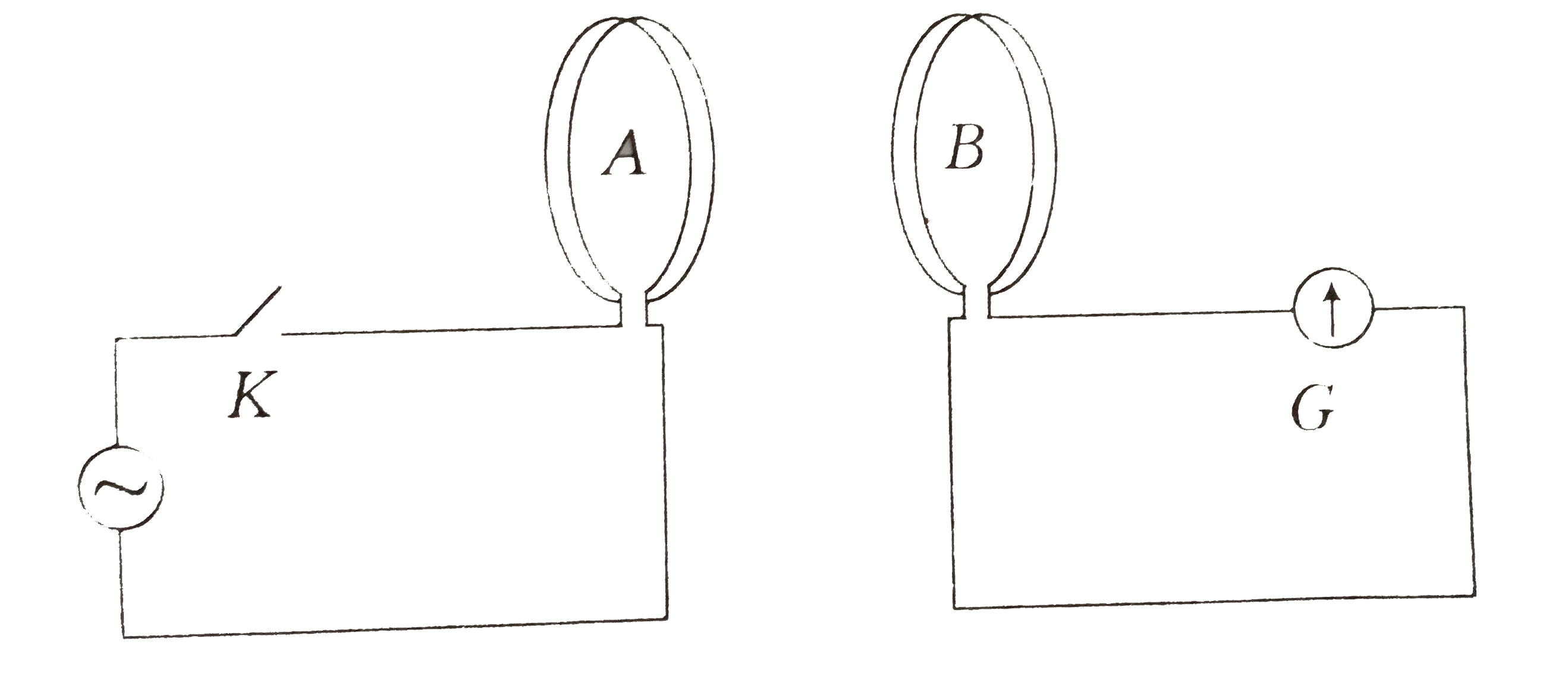
View SolutionThe diagram below shows two coils A and B placed parallel to each other at a very small distance. Coil A is connected to an ac supply. G is a very sensitive galvanometer When the key is closed.
View SolutionThe diagram below shows two coils A and B placed parallel to each other at a very small distance. Coil A is connected to an AC supply. G is a very sensitive galvanometer. When the key is closed
View SolutionA light bulb, a capacitor and a battery are connected together as shown here, with switch initially open. When the switch S is closed, then which one of the following is true

View SolutionA light bulb, a capacitor and a battery are connected together as shown here, with switch initially open. When the switch S is closed, then which one of the following is true

View SolutionWhat will be the direction of current in the coil A as the switch S is closed?
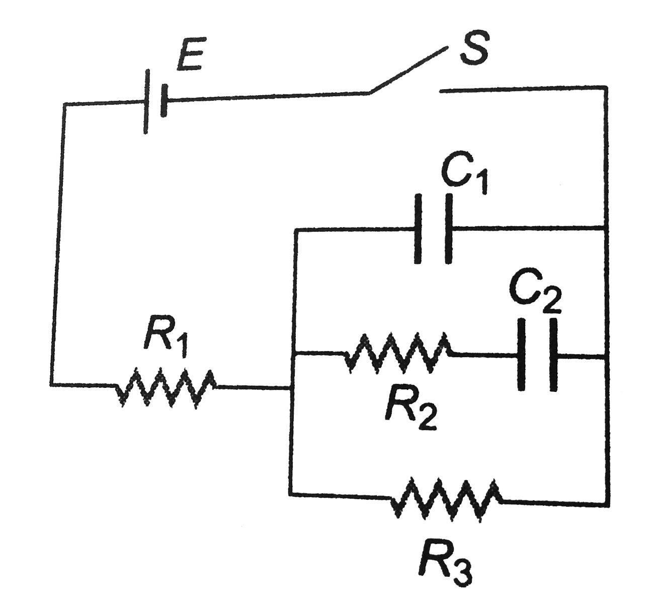
View SolutionThe ratio of initial to final current through the battery when the switch is closed in the figure is
View SolutionIn the circuit diagram the current through the battery immediately after the switch is closed is
View Solution