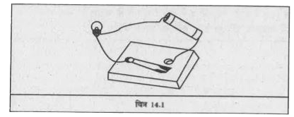
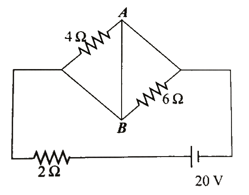
Draw the circuit diagram to represent the circuit shown in Fig.14.21.
Answer is -------
Related Solutions
चित्र 14.1 में दर्शाए गए विद्युत परिपव को निरूपित करने के लिए परिपव आरेख खींचिए।
View SolutionDraw the circuit diagram to represent the circuit shown infigure.
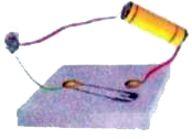
View SolutionDraw the circuit diagram to represent the circuit shown below.
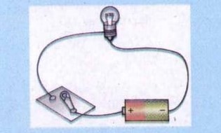
View SolutionDraw a circuit diagram to represent the electrical circuit shown in the figure.
View SolutionDraw the circuit diagram to represent the electrical circuit shown in the attached figure.
View SolutionDraw a phasor diagram for the circuit shown below.

View SolutionDraw a phasor diagram for the circuit shown bwl
View SolutionRepresent the connections shown below by a circuit diagram.
View SolutionRepresent the connections shown below by a circuit diagram.
View SolutionDraw the circuitdiagram to represent the circuit shown in given figure.
View SolutionThe logic circuit Fig. represents

View SolutionThe circuit diagram shown below is used to find the effective resistqnec of two resistors in series.which circuit diagram represents correctly
View SolutionIn the circuit diagram shown in Fig. the magnitude and direction of the flow of current respectively would be:
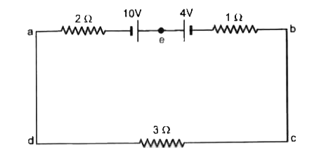
View SolutionIn the circuit shown in Fig. 7.45,
View SolutionIn the circuit shown in Fig. 7.45,
View SolutionIn the circuit shown in Fig.
View SolutionIn the circuit shown in Fig.
View SolutionWrite the truth table for the circuit shown in fig. Show that it represents a XOR gate.

View SolutionDraw the circuit diagrams of AND and NOT gates.
View Solution