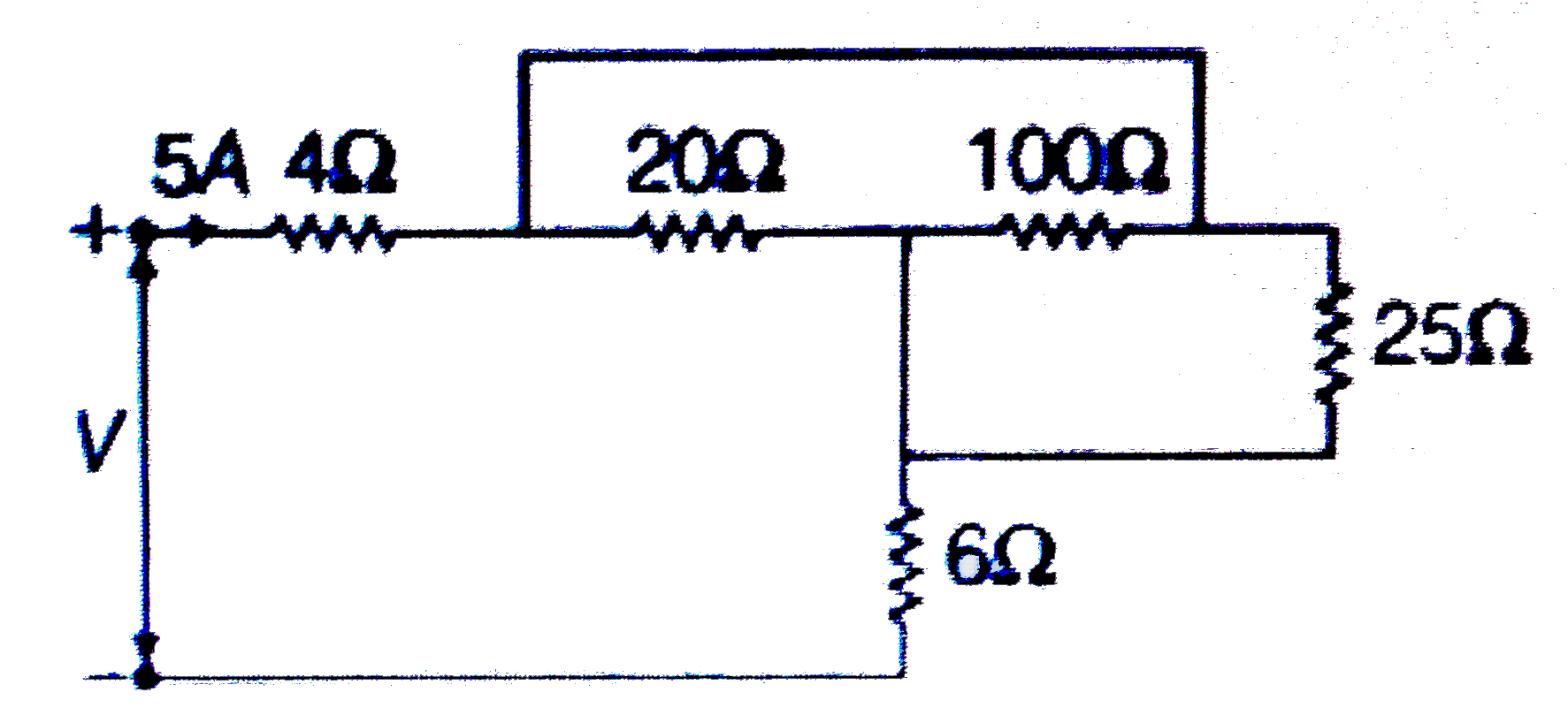
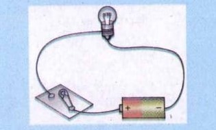
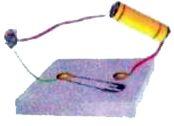
Draw the circuit diagram to represent the circuit shown below.
Video Solution
|
Answer
Step by step video & image solution for Draw the circuit diagram to represent the circuit shown below. by Physics experts to help you in doubts & scoring excellent marks in Class 7 exams.
Updated on:21/07/2023Topper's Solved these Questions
Similar Questions
Knowledge Check
A circuit is shown below.
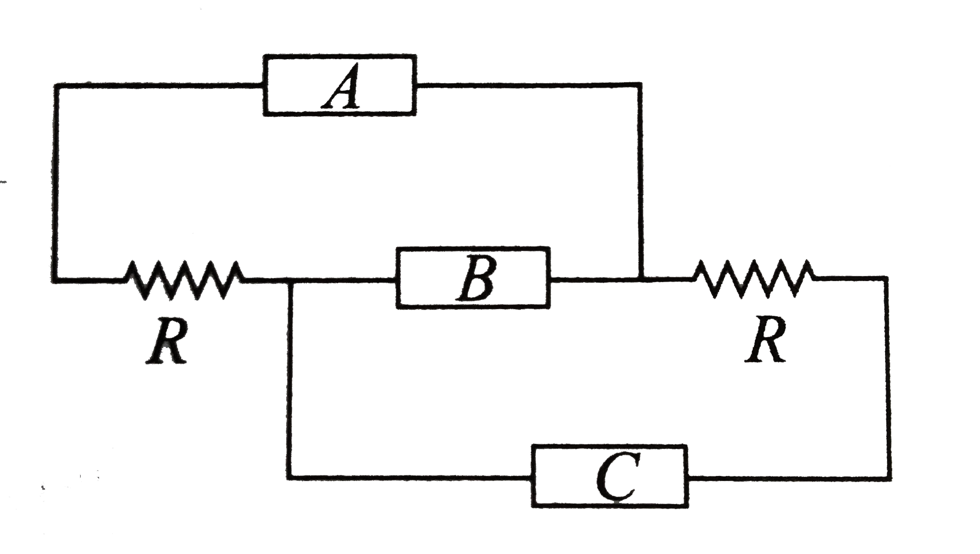 AIf A is an ideal ammeter, B an ideal battery of voltage V, and C an ideal voltmeter, the ratio reading of C/ reading of A is R.BIf A is a capacitor, B an ideal ammeter and C an ideal battery of voltage V, the potential difference across the capacitor is zero.CIf A is an ideal ammeter, B an ideal battery of voltage of V, and C an ideal voltmeter, the ratio reading of C/reading of A isR/2DIf A is a capacitor, B an ideal ammeter, and C an ideal battery of voltage V, the potential difference across the capacitor is 2 V.
In the circuit diagram shown
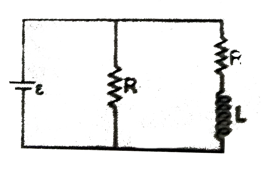 Atime constant is L/RBtime constant is 2L/RCsteady state current in inductor is 2ε/RDsteady state current in inductor is ε/2R
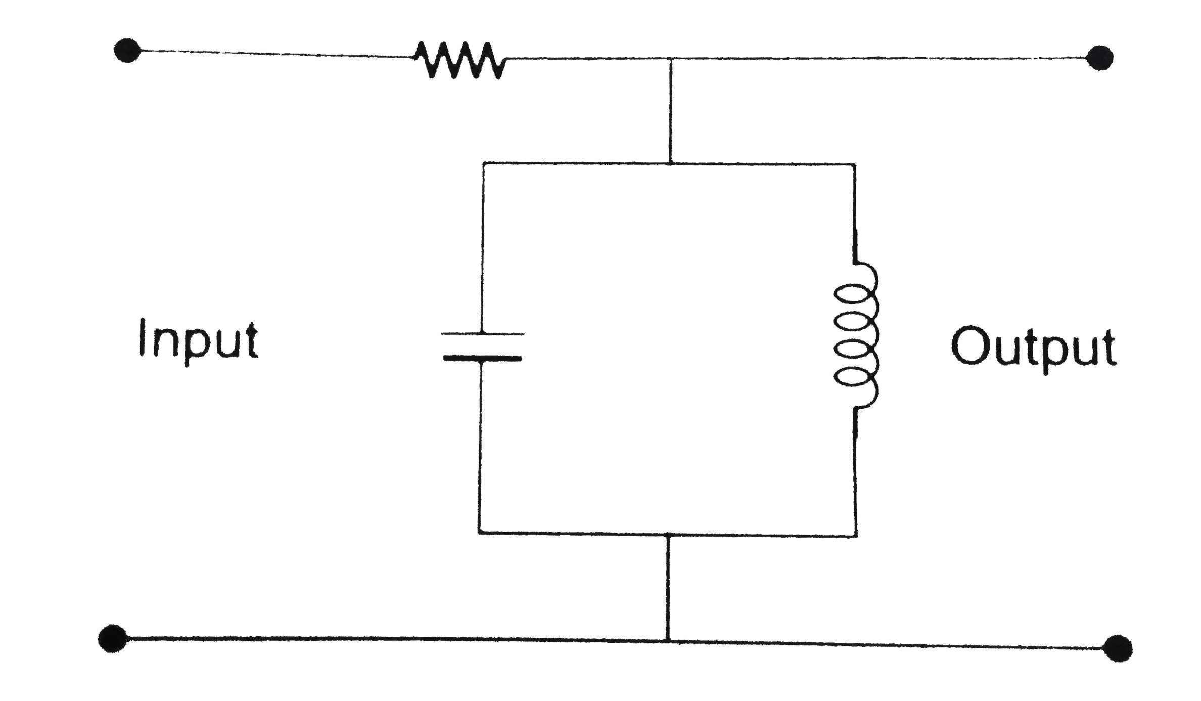
The circuit shown below acts as
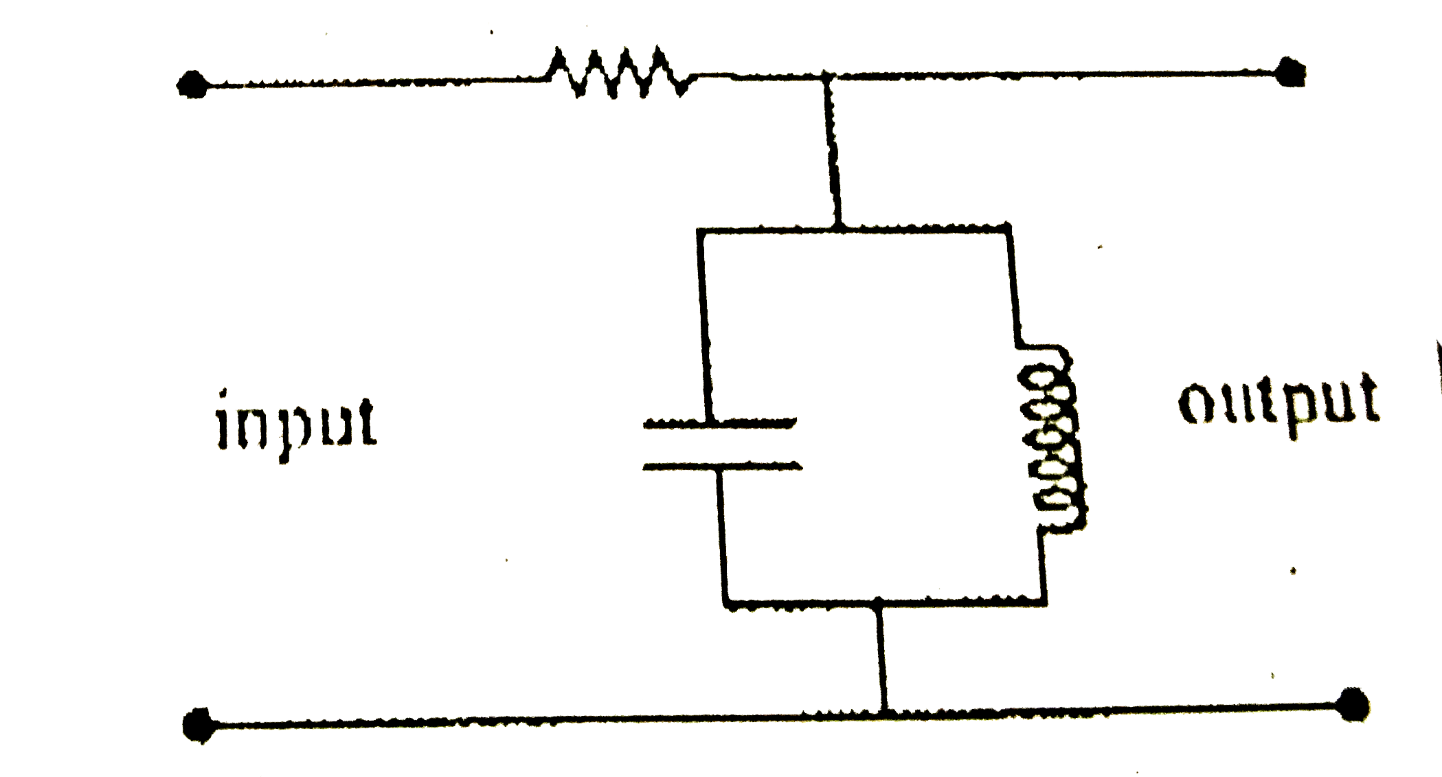 Atuned filterBlow pass filterChigh pass filterDrectifier



 .
.