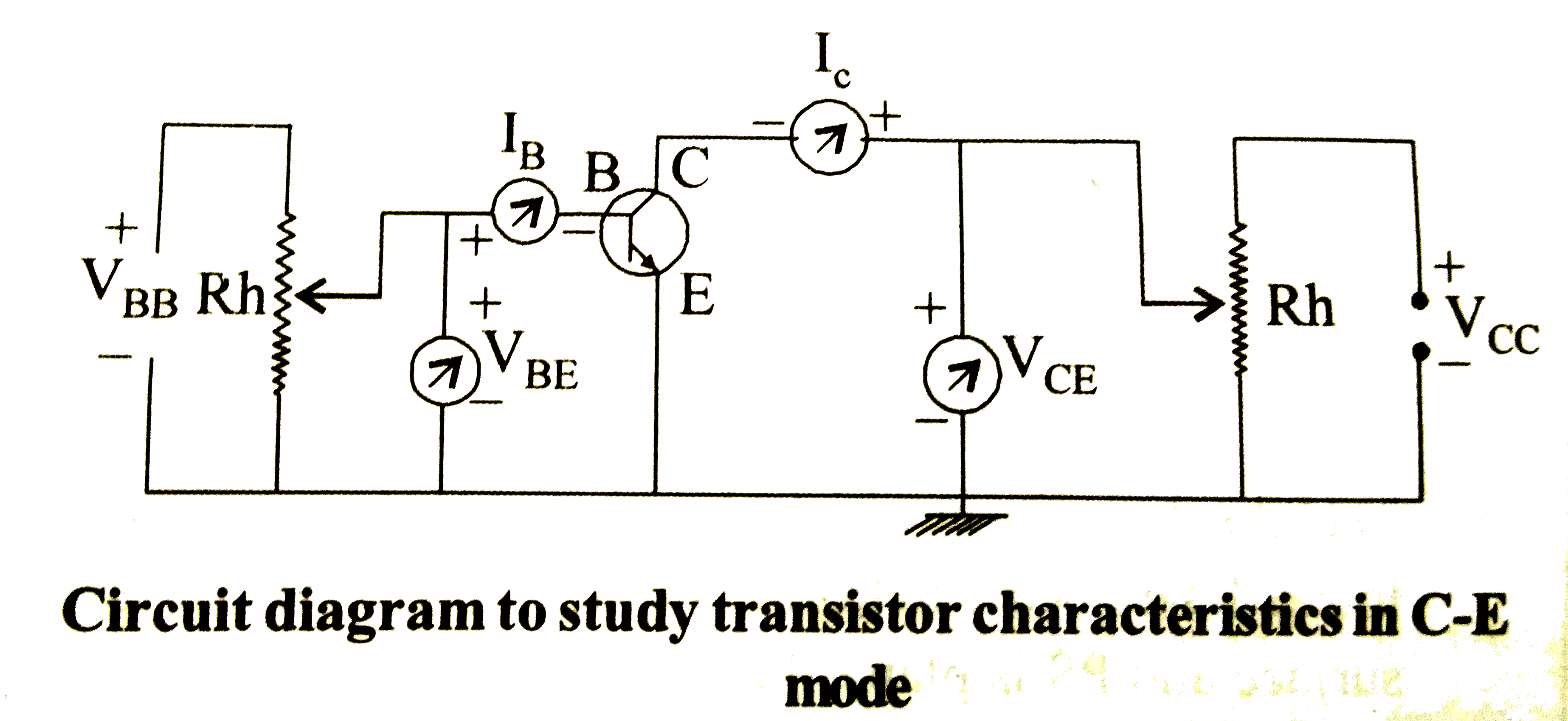
Draw the circuit diagram for studying the characteristics of a transistor in common emitter configuration. Explain briefly and show how input and output characteristics are drawn.


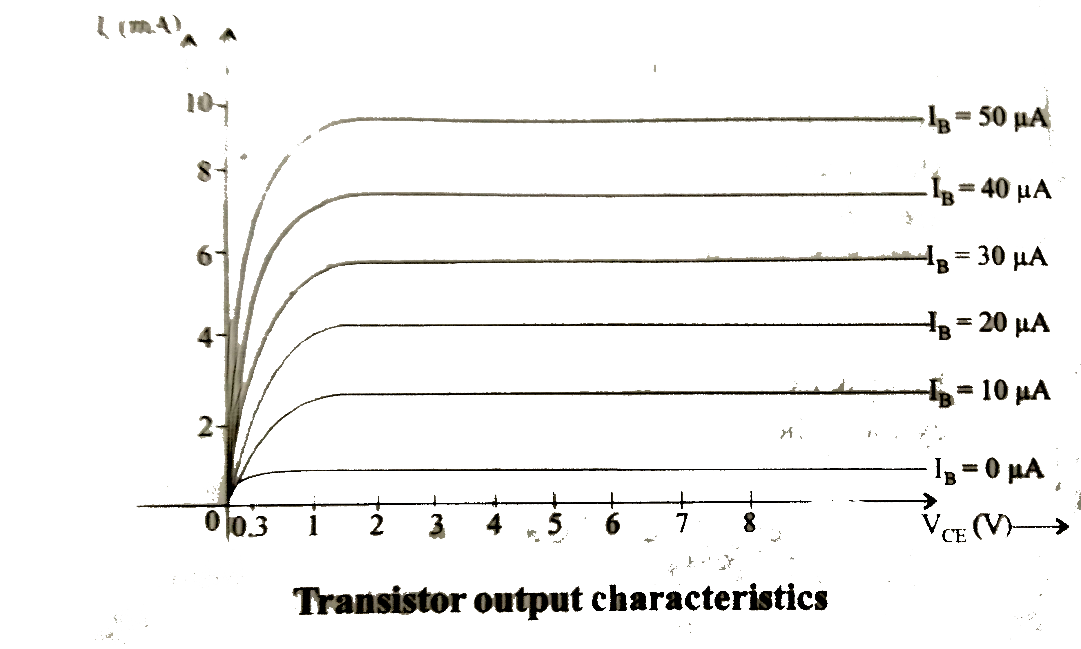
For Collector-Emitter mode, it is a graph of collector current (Ic) versus collector voltage (VCE), for the fixed value of the base courrent. For output charateristics,IB is kept constant VCE is increased in small steps and IC is recorded at every step.
From output characteristics, it is observed that
(i) When IB=0,IC is nearly zero, hence the trasistor is an cut off region.
(ii) For VCE<0.3V,IC increases with VCE and can be controlled by VCE,
(iii) When VCE>VBE>0.7V,C−E jnuction gets reverse baised and IC gets saturated, hence the transistor is in active reagion.
When VCE<0.2V, both the junctions get forward biased and IC can no longer be controlled by VCE, hence the transistor is the saturation region.
The dynamic output resistance of transistor is
r0=(ΔVCEΔIC)IB is constant
In C-E mode, output resistance varies from few KΩ to KΩ.
Similar Questions
Draw a circuit diagram to obtain the characteristics of a n-p-n transistor in common base configuration . Give shape of input and output characteristic curves.
View SolutionDraw a circuit diagram to study characteristics of a transistor (pnp or ppn) in common emitter configuration. Draw the sketch of (i) input characterisitics and (ii) output characteristics for this configuration.
View SolutionDraw a circuit diagram to study characteristics of n-p-n transistor in CE configuration. Draw the sketch of input and output characteristics of this configuration . Define current amplification factor ?
View SolutionDefine the dynamic output resistance of a transistor amplifier in common - emitter configuration.
View SolutionDraw the circuit diagram for studying the characteristics of a transistor in common emitter configuration. Explain briefly and show how input and output characteristics are drawn.
View SolutionDraw the circuit diagram for studying the characteristics of a transistor in common emitter configuration. Explain briefly and show how input and output characteristics are drawn.
View SolutionThe typical output characteristics curve for a transistor working in the common-emitter configuration is shown in the figure.

View SolutionWith a neat labelled diagram, explain the actionn of npn transistor in common base configuration
View SolutionDraw circuit diagram for n-p-n transistor to draw input and output characteristics in common base configuration. Draw the input and ouput curves and explain them.
View SolutionWith the help of a labelled circuit diagram, explain how an n-p-n transistor can be used as an amplifier in common-emitter configuration. Explain how the input and output voltages are out of phase by 1800 for a common-emitter transistor amplifier.
View Solution
