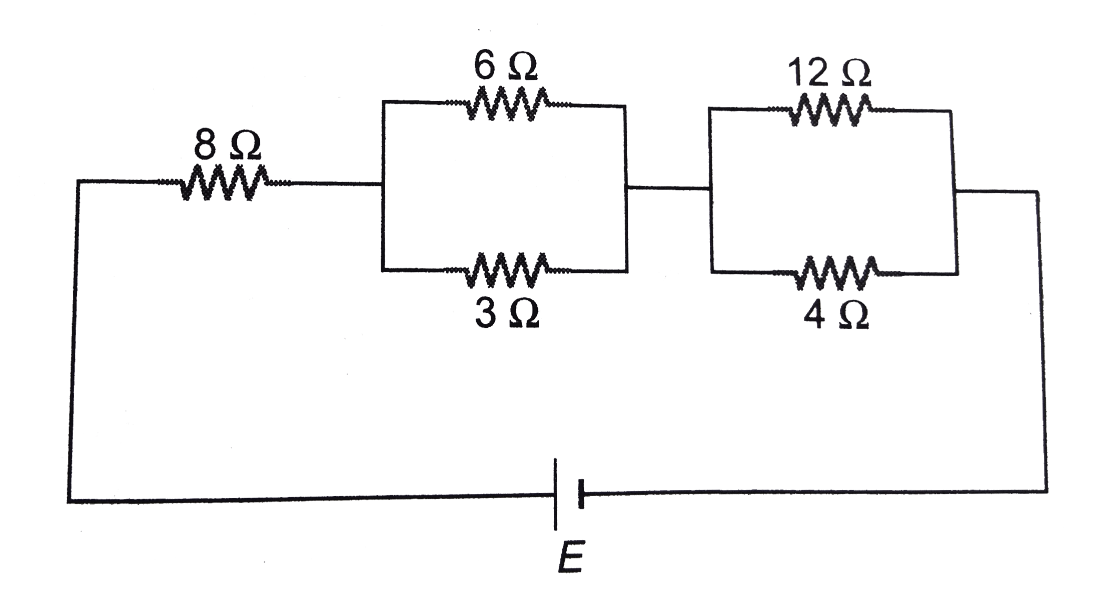
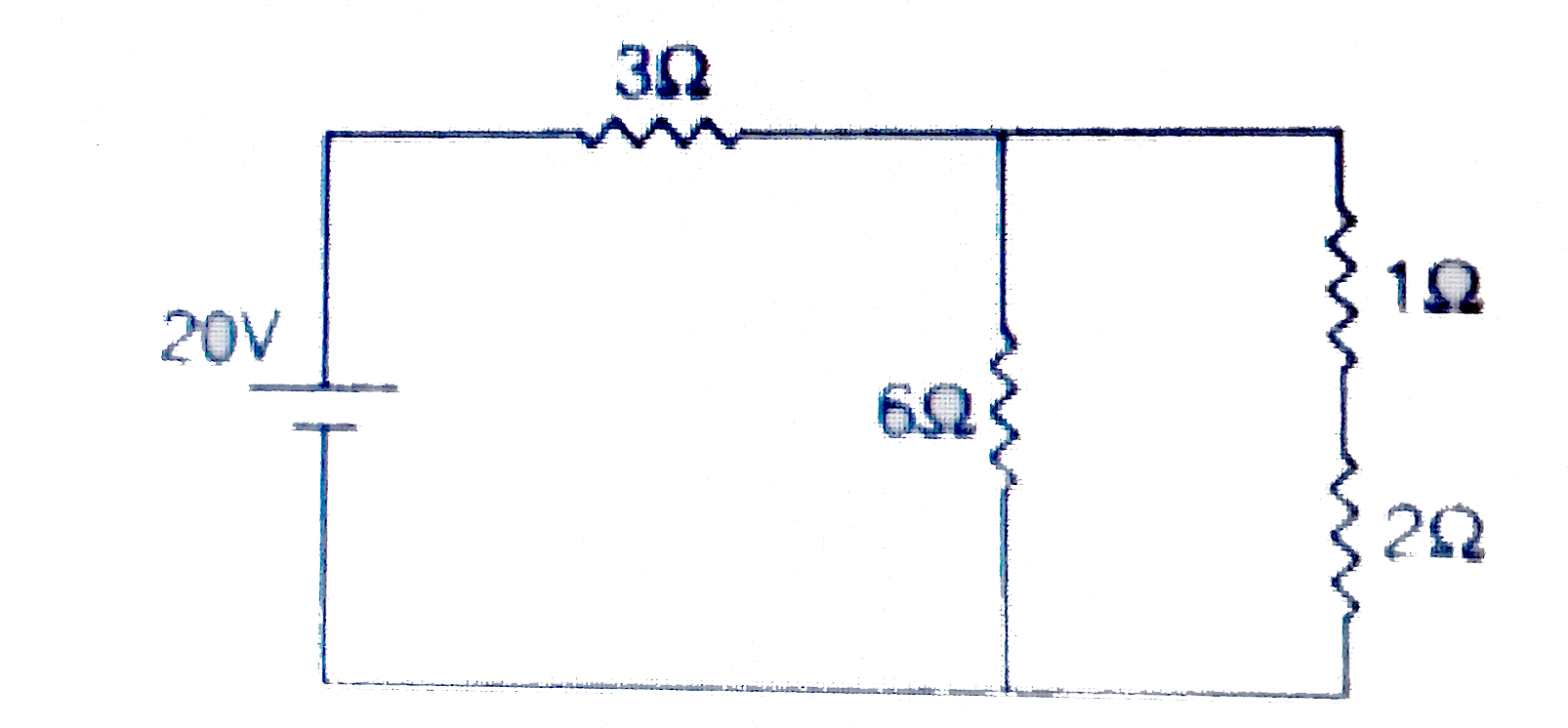
In the circuit shown in figure find the heat developed across each resistance in 2s.
Video Solution
Text Solution
The 6Ωand3Ω resistances are in parallel. So, their combined resistance is
1R=16+13=12
or R=2Ω
The equivalent simple circuit can be drawn as shown.
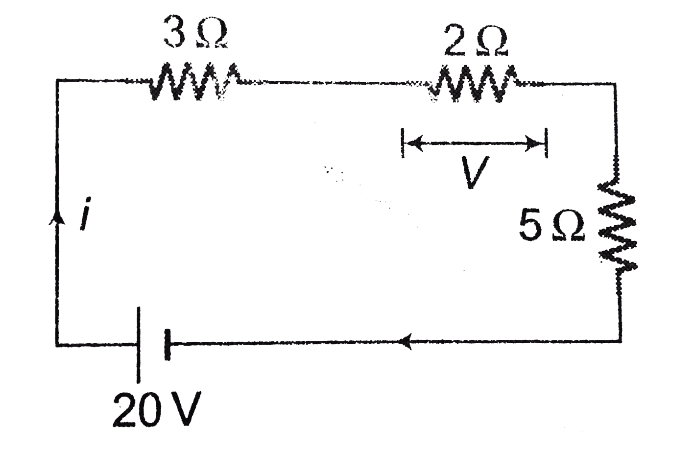
Current in the circuit i=netemftotal resistance=203+2+5=2A
V=iR=(2)(2)=4V
i.e. Potential difference across 6Ωand3Ω resistance are 4V. Now,
H3Ω (which is connected in series) =i2Rt=(2)2(3)(2)=24J
H6Ω=V2Rt=(4)26(2)=163J
H3Ω (which is connected in parallel ) =V2Rt=(4)2(2)3=323J
and H5Ω=i2Rt=(2)2(5)(2)=40J
|
Topper's Solved these Questions
- CURRENT ELECTRICITYBOOK - DC PANDEYCHAPTER - CURRENT ELECTRICITYEXERCISE - Example Type 1
2 Videos
- CURRENT ELECTRICITYBOOK - DC PANDEYCHAPTER - CURRENT ELECTRICITYEXERCISE - Example Type 2
1 Videos
- COMMUNICATION SYSTEMBOOK - DC PANDEYCHAPTER - COMMUNICATION SYSTEMEXERCISE - Subjective
11 Videos
- ELECTROMAGNETIC INDUCTIONBOOK - DC PANDEYCHAPTER - ELECTROMAGNETIC INDUCTIONEXERCISE - Medical entrances gallery
25 Videos
Similar Questions
Knowledge Check
In the circuit shown in figure heat developed across 2Ω,4Ωand3Ω resistances are in the ratio
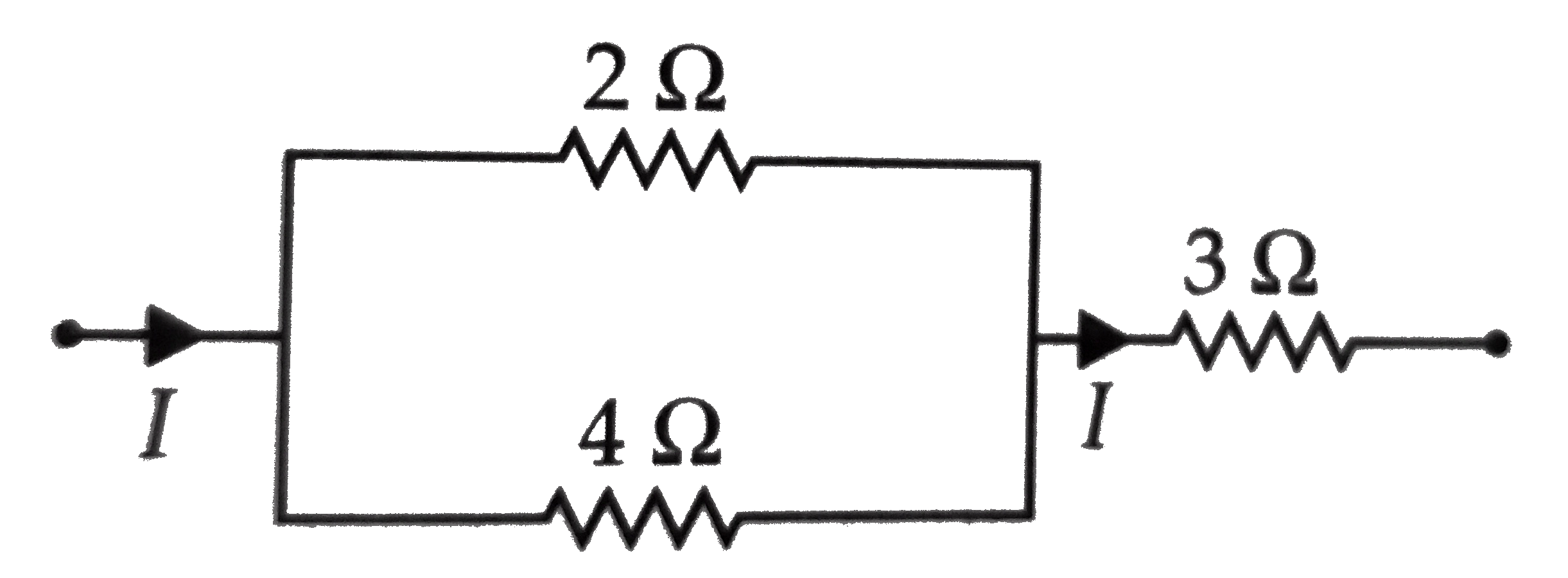 A2:4:3B1:4:27C4:8:27D8:4:27
In the L-R circuit as shown in figure, potential difference across the resistance at some instant is 4 V. Then
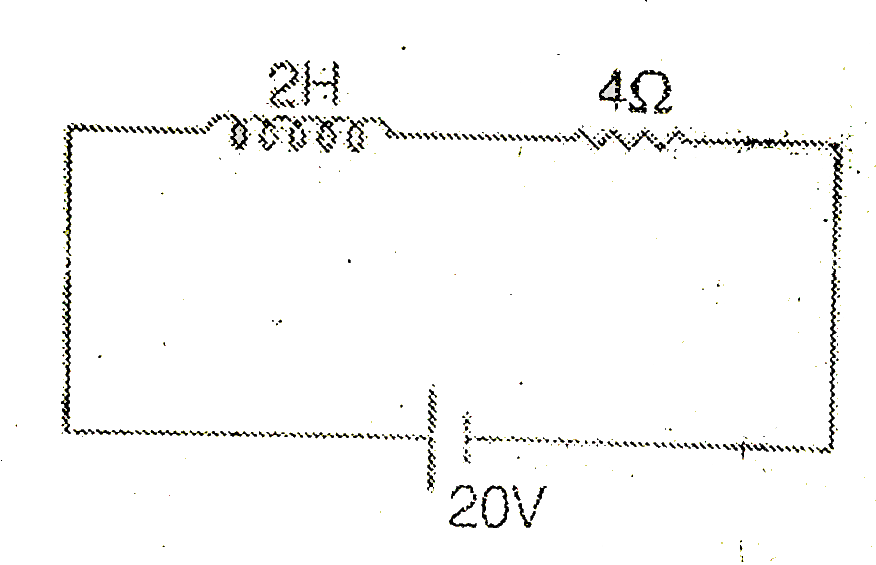 Acurrent is increasing at a rate of 8A/s at this instantBpower supplied by the battery at this instant is 20WCpower stored in the magnetic field at this instant is 16WDcurrent in the circuit at this instant is 1A
In the circuit shown in figure
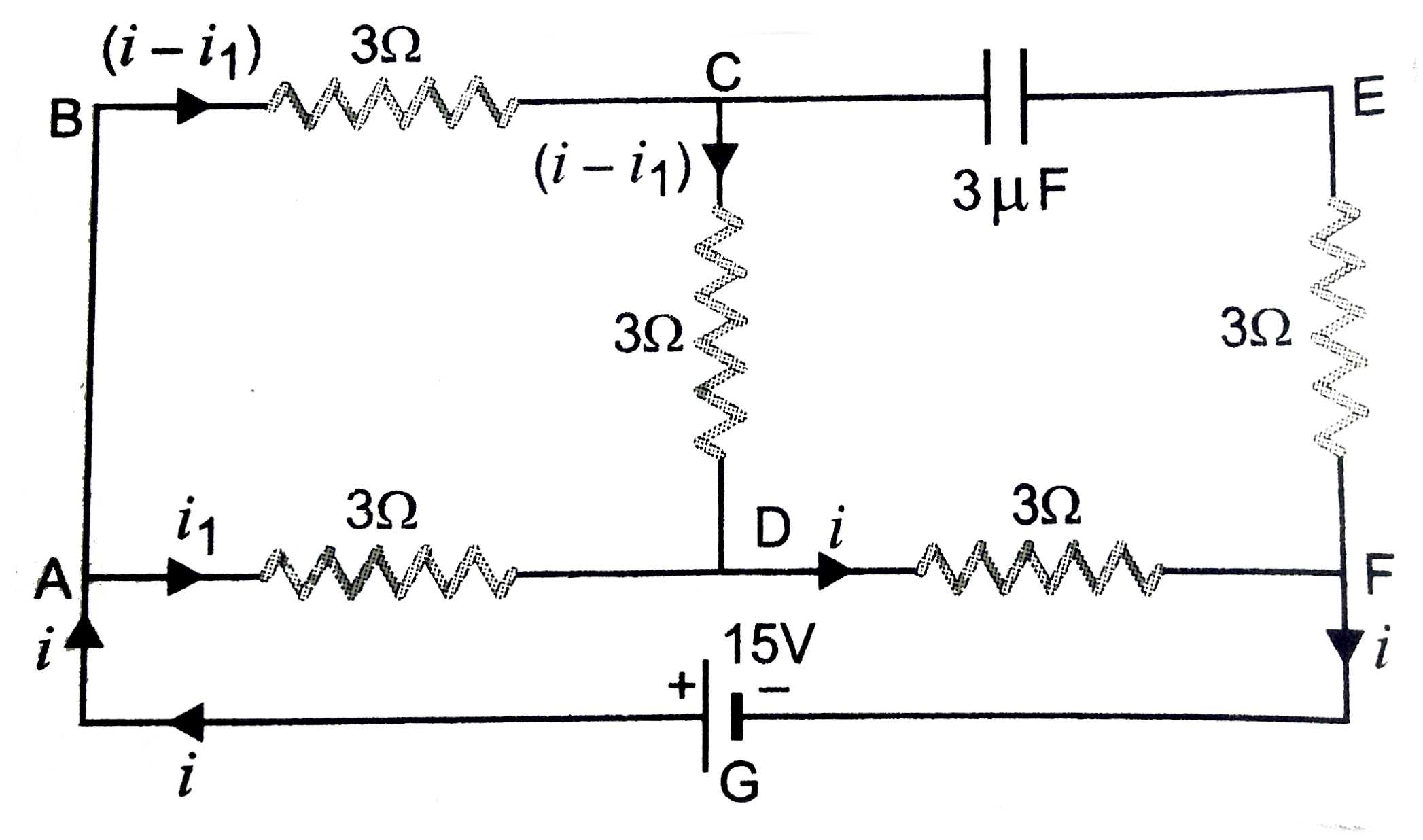
Find the potential differnece across capacitor.
View SolutionIn the circuit shown in figure potential difference across
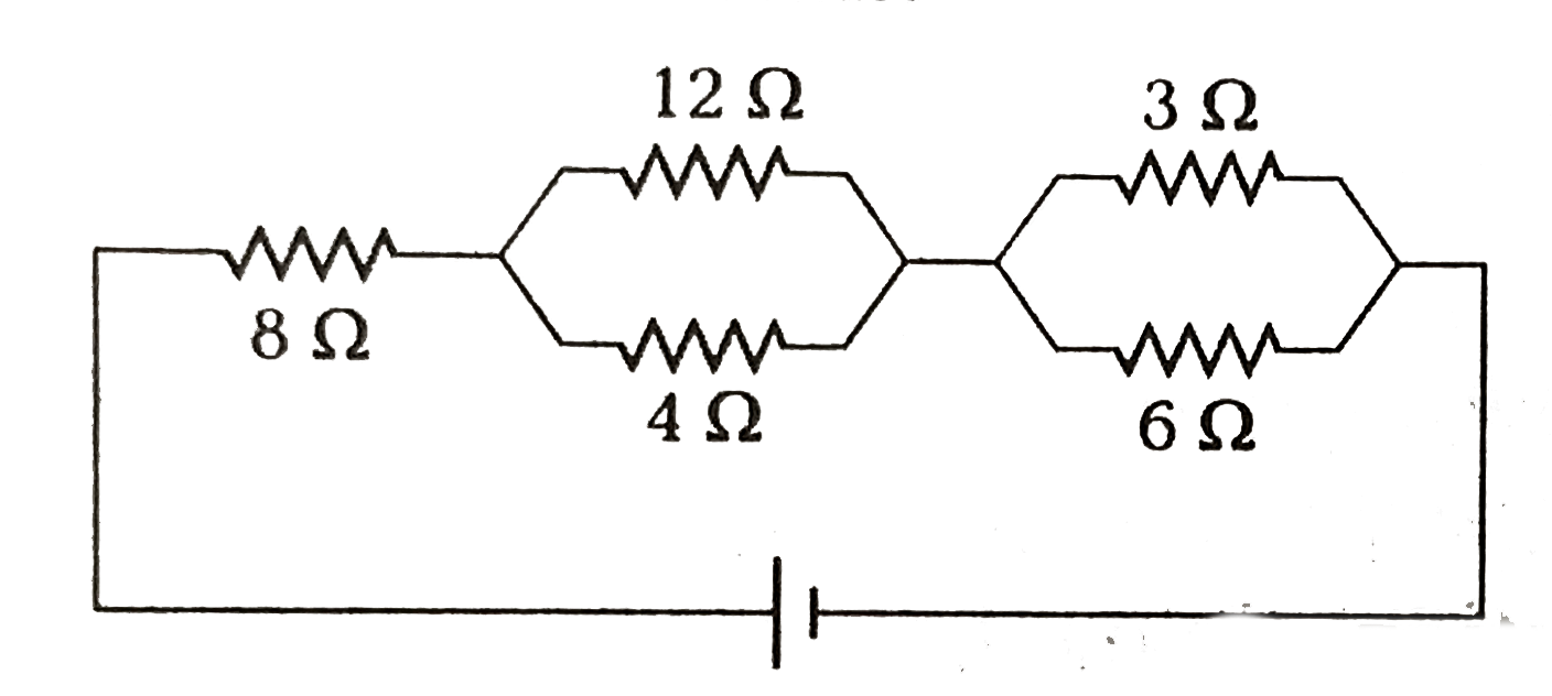
View SolutionIn the circuit diagram shown in figure, potential difference across 3Ω resistance is 20 V. Then, match the following two columns.
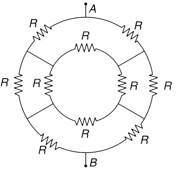
View SolutionIn the circuit shown in figure find the equivalent resistance across points A and B.
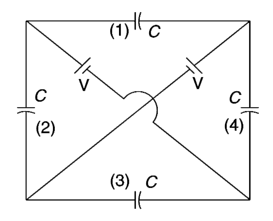
View SolutionIn the circuit shown in the figure, find charge on each capacitor.
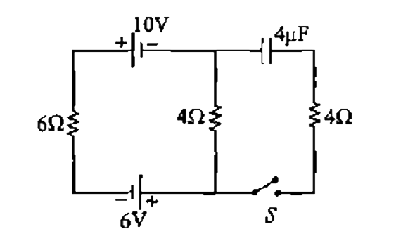
View SolutionIn the circuit shown in figure-3.238, find the current in 6Ω resistance just after closing the switch S.
View Solution


