
Assertion : In the circuit shown in figure ammeter and voltmeter are non-ideal. Why positions of ammeter and voltmeter are changed, reading of ammeter will increase while of voltmeter will decrease.
Reason : Resistance of an ideal ammeter is zero while that of an ideal voltmeter is infinite.
If both Assertion and Reason are true and the Reason is correct explanation of the Assertion.
If both Assertion and Reason are true but Reason is not the correct explanation of Assertion.
If Assertion is true, but the Reason is false.
If Assertion is false but the Reason is true.
The correct Answer is:B
Even if ammeter is non ideal its resistance should be small and net parallel resistance is less than the smallest individual resistance.
∴Rnet< resistance of ammeter in changed situation. Hence, net resistance of the circuit will decrease. So, main current will increase. But maximum percentage of main current will pass through ammeter (in parallel combination) as its resistance is less. Hence, reading of ammeter wil increase.
Initial voltmeter reading=emf of battery
Final voltmeter reading=emf of battery
-potential drop across shown resistancce.
Hence, voltmeter reading will decrease.
Topper's Solved these Questions
- CURRENT ELECTRICITYBOOK - DC PANDEYCHAPTER - CURRENT ELECTRICITYEXERCISE - Level 1 Objective
40 Videos
- CURRENT ELECTRICITYBOOK - DC PANDEYCHAPTER - CURRENT ELECTRICITYEXERCISE - OBJECTIVE_TYPE
1 Videos
- CURRENT ELECTRICITYBOOK - DC PANDEYCHAPTER - CURRENT ELECTRICITYEXERCISE - Exercise 23.13
2 Videos
- COMMUNICATION SYSTEMBOOK - DC PANDEYCHAPTER - COMMUNICATION SYSTEMEXERCISE - Subjective
11 Videos
- ELECTROMAGNETIC INDUCTIONBOOK - DC PANDEYCHAPTER - ELECTROMAGNETIC INDUCTIONEXERCISE - Medical entrances gallery
25 Videos
Similar Questions
Knowledge Check
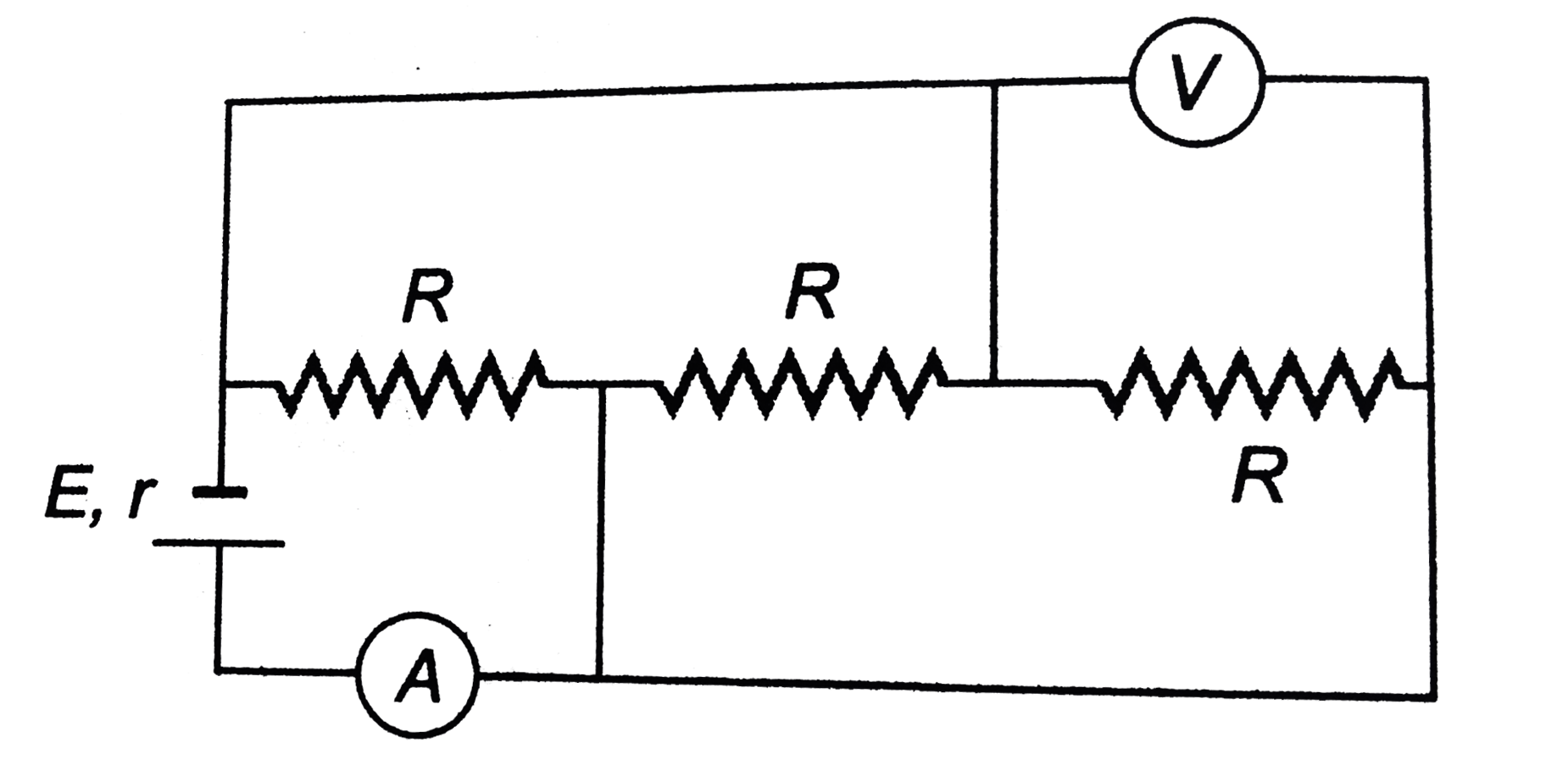
In the circuit shown in figure ammeter and voltmeter are ideal. If E=4V,R=9Ω and r=1Ω then readings of ammeter and voltmeter are
 A1A,3VB2A,3VC3A,4VD4A,4V
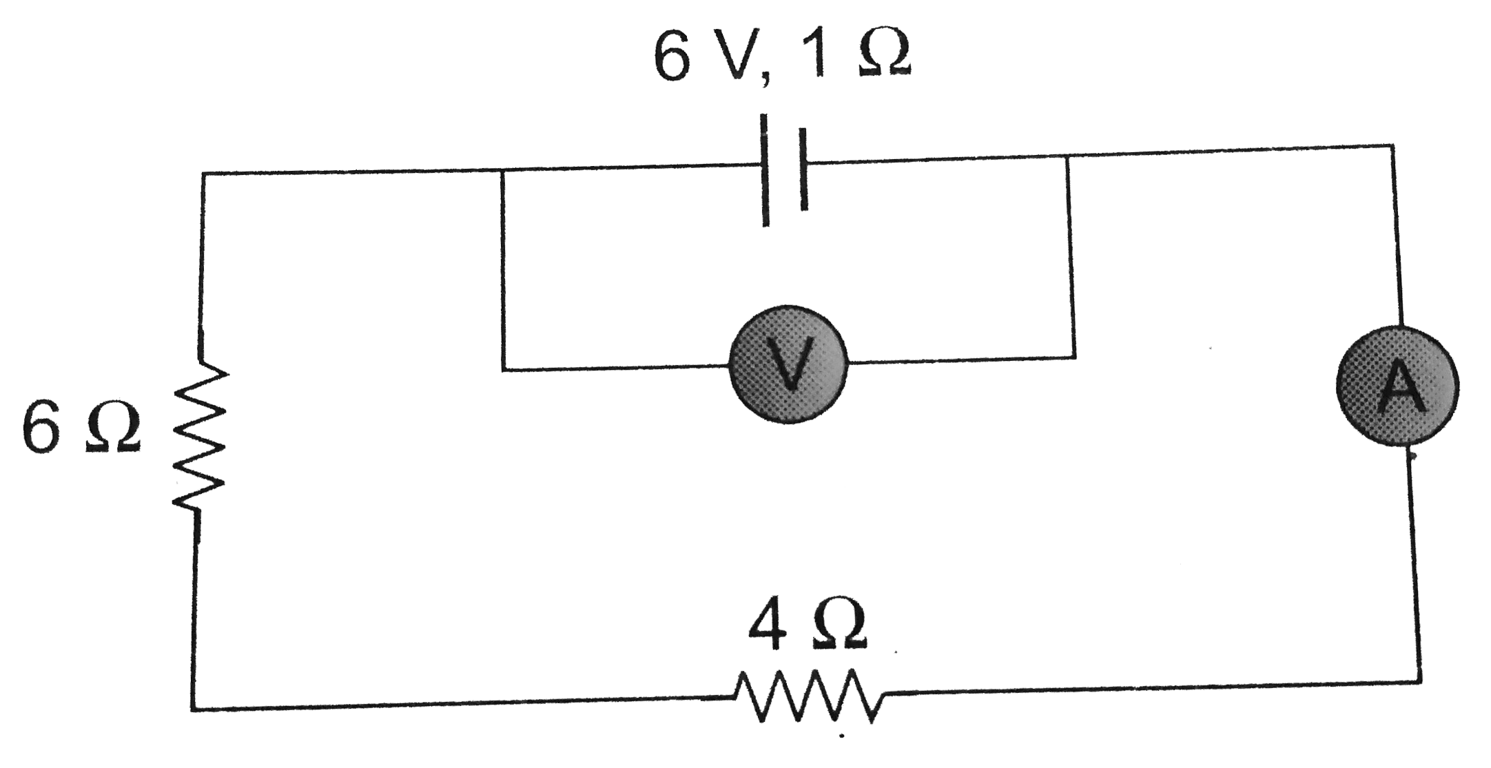
In the circuit shown here, the readings of the ammeter and voltmeter are
 A6A,60VB0.6A,6VC6/11A,60/11VD11/6A,11/60V
In the circuit shown, A and V are ideal ammeter and voltmeter respectively. Reading of the voltmeter will be
 A2VB1VC0.5VDZero
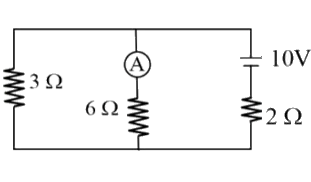
The reading of the ideal ammeter will be (Resistance of ideal ammeters is zero)
View Solution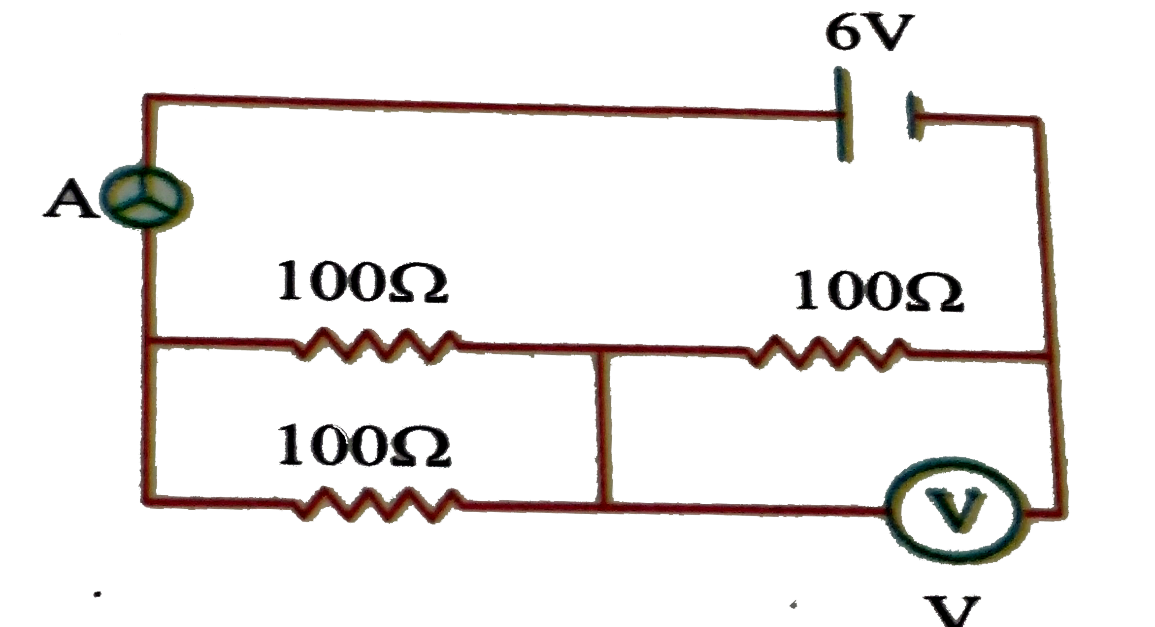
In the circuit shown, the reading of the voltmeter and the ammeter are
View Solution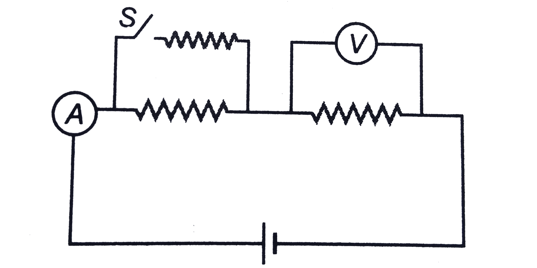
Assertion: In the circuit shown in figure after closing the switch S reading of ammeter will increase while that of voltmeter will decrease.
Reason : Net resistance decreases as parallel combination of resistors is increased,
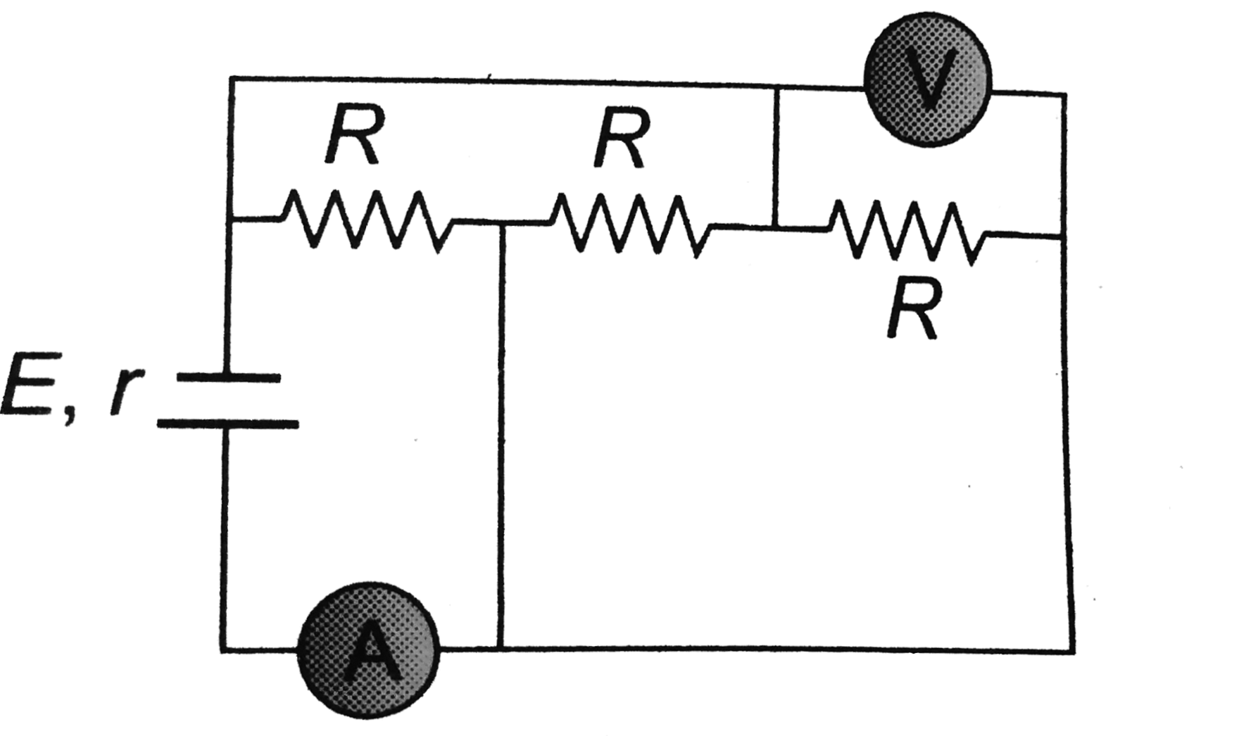
View SolutionIn the circuit shwon in figure, ammeter and voltmeter are ideal. E=4V,R=15Ω and r=1Ω, then reading of ammter (in A) and voltmeter (in V) respectively are:
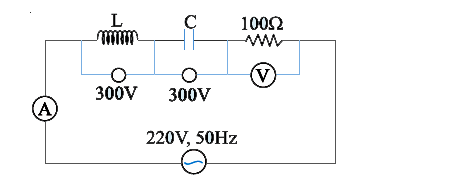
View SolutionIn the circuit shown in figure, what will be the readings of voltmeter and ammeter?
View Solution
