In the circuit shown in figure, reading of ammeter will
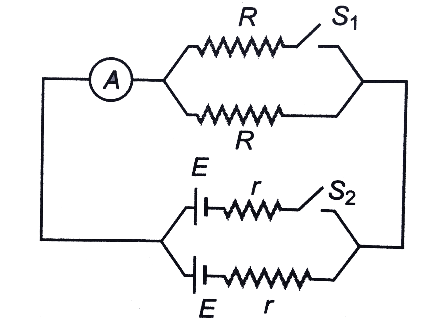
shows no deflection if S1 is closed
decrease if S2 is closed
increase if S2 is closed
decrease if S2 is closed
The correct Answer is:C
By closing S1 net external resistance wil decrease. So, main current will increase.
By closing S2 net emf will remain unchange but net internal resistance will decrease. Hence, main current will increase.
Topper's Solved these Questions
- CURRENT ELECTRICITYBOOK - DC PANDEYCHAPTER - CURRENT ELECTRICITYEXERCISE - Level 2 Comprehension Example Type
2 Videos
- CURRENT ELECTRICITYBOOK - DC PANDEYCHAPTER - CURRENT ELECTRICITYEXERCISE - Level 2 Subjective
13 Videos
- CURRENT ELECTRICITYBOOK - DC PANDEYCHAPTER - CURRENT ELECTRICITYEXERCISE - Level 2 Single Correct
26 Videos
- COMMUNICATION SYSTEMBOOK - DC PANDEYCHAPTER - COMMUNICATION SYSTEMEXERCISE - Subjective
11 Videos
- ELECTROMAGNETIC INDUCTIONBOOK - DC PANDEYCHAPTER - ELECTROMAGNETIC INDUCTIONEXERCISE - Medical entrances gallery
25 Videos
Similar Questions
In the circuit shown in the figure, reading of ammeter is I1 when only S1 is closed, reading of of ammeter is is I2 when only S2 is closed and reading of Ammeter,is I3 when both S1 and S2 are closed then
_PHY_E05_114_Q01.png) .
.
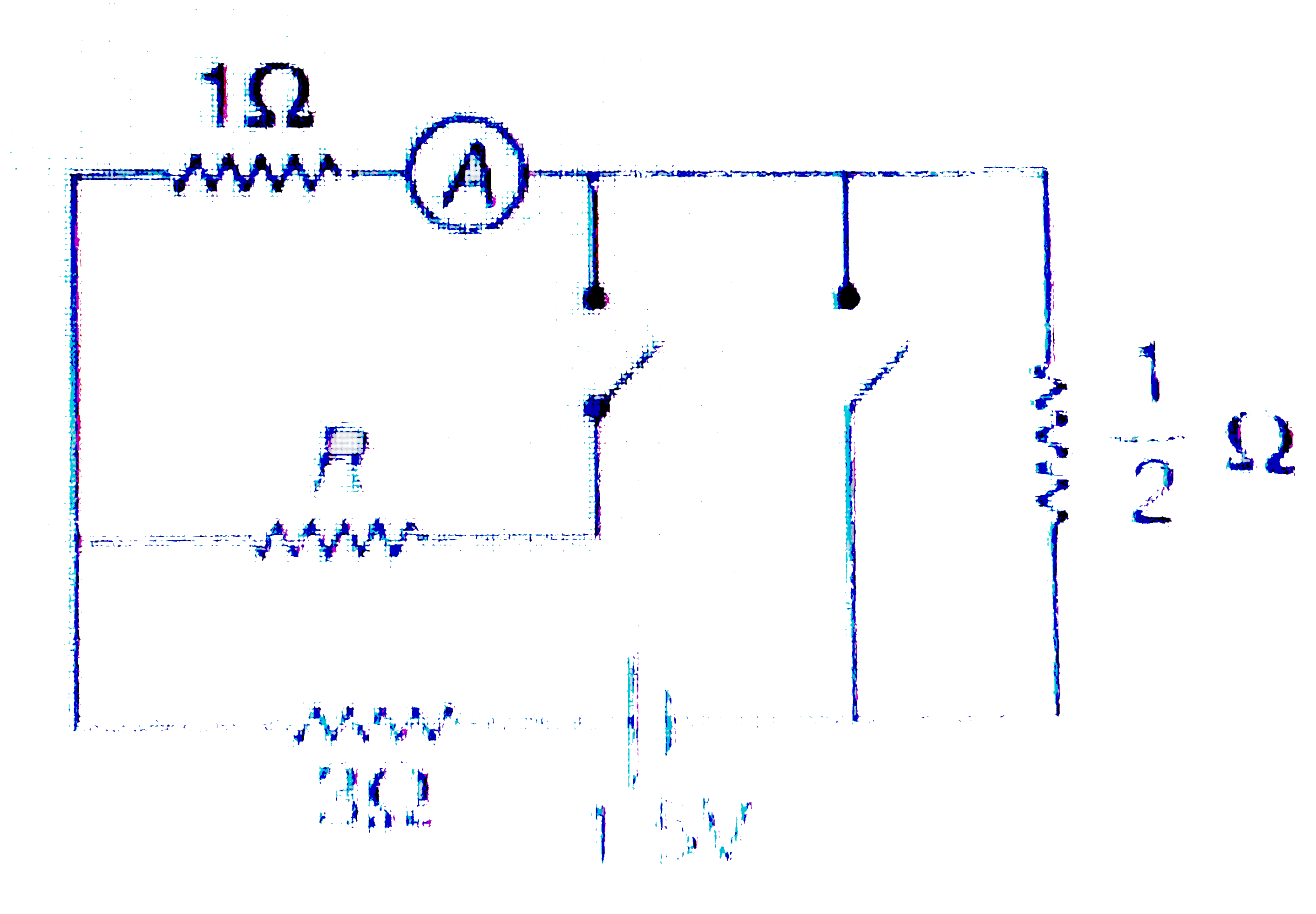
View SolutionIn the circuit as shown in figure , the reading of ammeter (ideal) in the same with both switches one and both switches closed. Find the resistance R ( in Ω)
View Solution
Knowledge Check
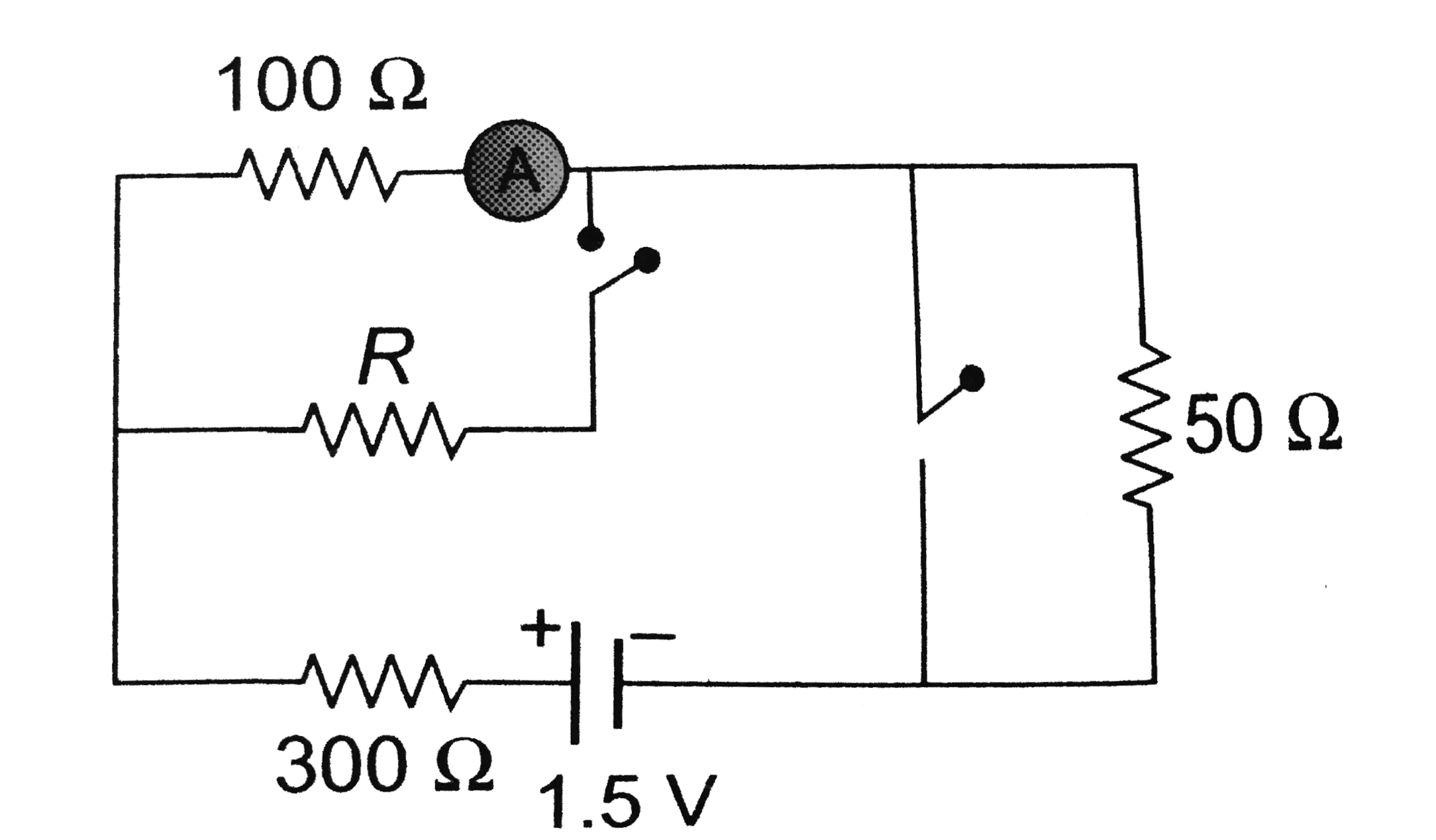
In the circuit shown in figure the reading of ammeter is the same with both switches open as with both closed. Then find the resistance R. (ammeter is ideal).
 A550ΩB400ΩC350ΩD600Ω
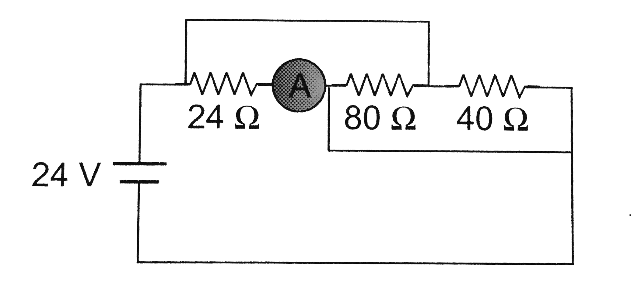
In the circuit shown, the reading of ammeter is:
 A0.2AB0.6AC2AD1A
In the circuit shown in figureure, the reading of the AC ammeter is
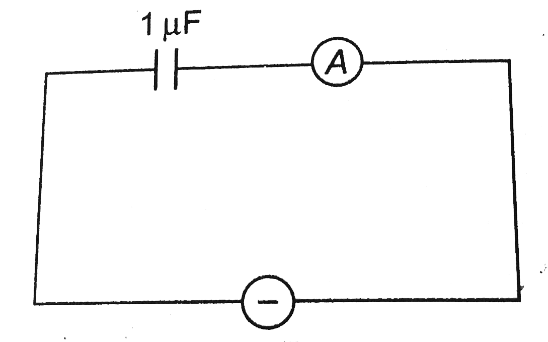 .A20√2mAB40√2mAC20mAD40mA
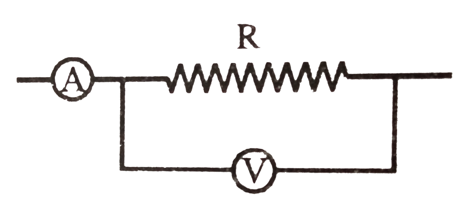
A part of a circuit is shown in figure. Here reading of ammeter is 5 ampere and voltmeter is 96V & voltmeter resistance is 480 ohm. The find the resistance R.
View SolutionFor the AC circuit shown in the figure the reading' of ammeter and voltmeter are 5A and 50√5V, respectively. The rms value of (AC) source (in volt) is
'(##CEN_KSR_PHY_JEE_C24_E01_029_Q14##)'
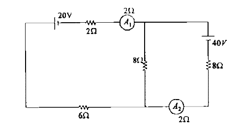
View SolutionIn the circuit shown in figure-3.388, each ammeter has coil resistance 2Ω, find reading of the two ammeters.
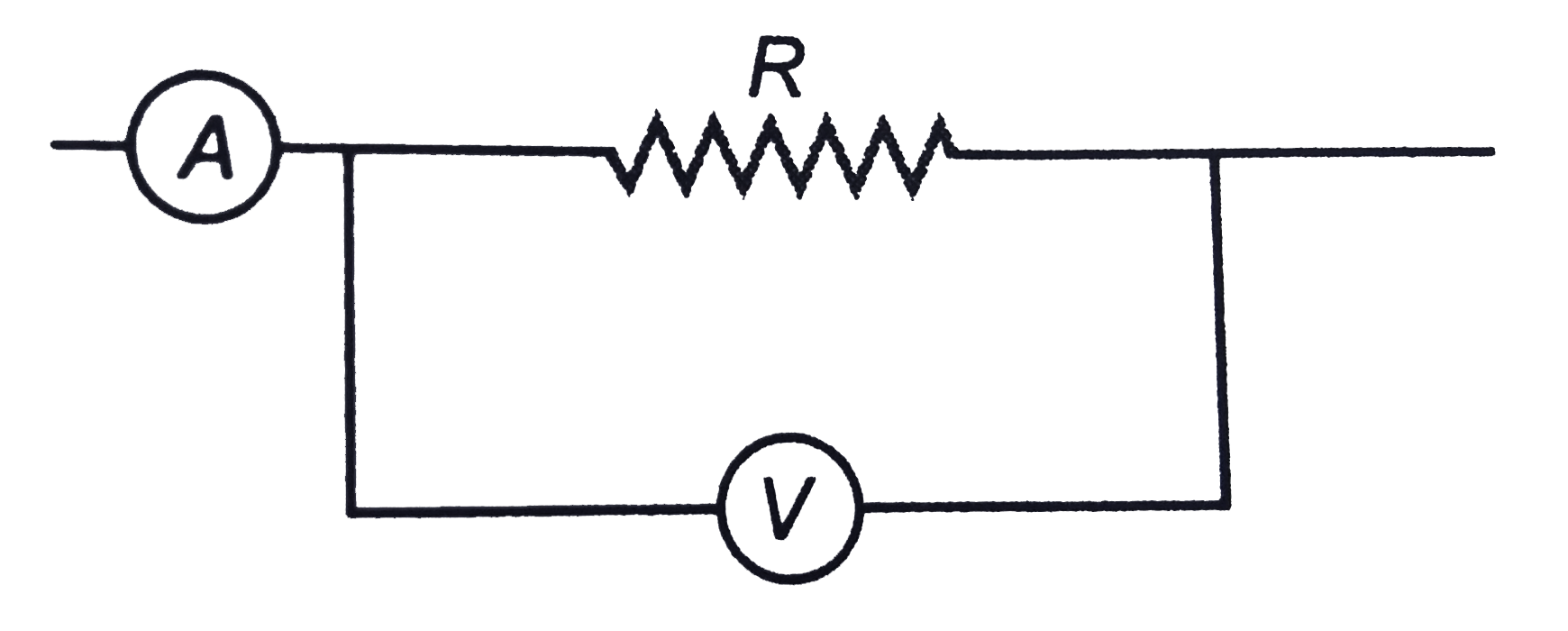
View SolutionA part of a circuit is shown in figure. Here reading of ammeter is 5A and voltmeter is 100V. If voltmeter resistance is 2500ohm, then the resistance R is approximately
View SolutionIn the circuit shown, the reading of the ammeter if diode is not ideal, will be

View Solution
