In the circuit shown in figure find 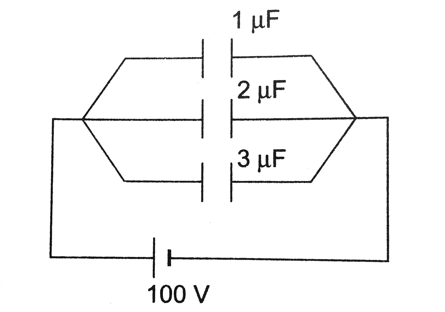
a. the equivalent capacitance and
b. the charge stored in each capacitor.
a. the capacitors are in parallel. Hence, the equivalent capacitance is
C=C1+C2+C3
or C=(1+2+3)=6μF
b. total charge drawn from the battery K
q=CV−6×100μC=600μC
This charge will be distributed in the ratio of their capacities. Hence,
q1:q2:q3=C1:C2:C3=1:2:3
∴q1=(11+2+3)×600=100μC
q2=(21+2+3)×600=200μC
and q3=(31+2+3)×600=300μC
Alternate solution: Since the capacitors are in parallel the PD across each of them in 100V.
Therefore from q=CV, the charge stored in 1μF capacitor is 100μC, in 2μF capacitor is 200μC and that in 3μF capacitor is 300μC
Topper's Solved these Questions
- CAPACITORSBOOK - DC PANDEYCHAPTER - CAPACITORSEXERCISE - Exercise
155 Videos
- CAPACITORSBOOK - DC PANDEYCHAPTER - CAPACITORSEXERCISE - OBJECTIVE_TYPE
1 Video
- ATOMSBOOK - DC PANDEYCHAPTER - ATOMSEXERCISE - MEDICAL ENTRANCES GALLERY
42 Videos
- COMMUNICATION SYSTEMBOOK - DC PANDEYCHAPTER - COMMUNICATION SYSTEMEXERCISE - Subjective
11 Videos
Similar Questions
Knowledge Check
In the circuit shown in figure find
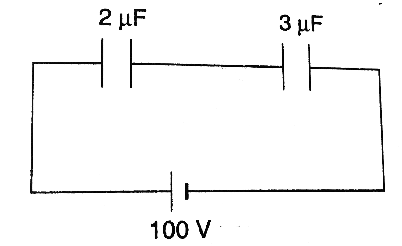
a. the equivalent capacitance
b. the charge stored in each capacitor and
c. the potential difference across each capacitor.A1.2μF 120μC 60Vand40VB1.2μF 120μC 60Vand20VC1.2μF 12μC 60Vand40VD12μF 120μC 60Vand40VFor the circuit shown in figure, the equivalent capacitance of the combination is
 A13μFB(3013)μFC(5410)μFD1μF
Consider the circuit shown in the figure below :
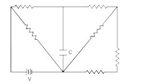
All the resistors are identical. The charge stored in the capacitor, once it is fully charged, isA0B513CVC23CVD58CV
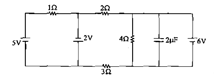
In the circuit shown in figure-3.355, the current in 1Ω. resistance and charge stored in the capacitor are
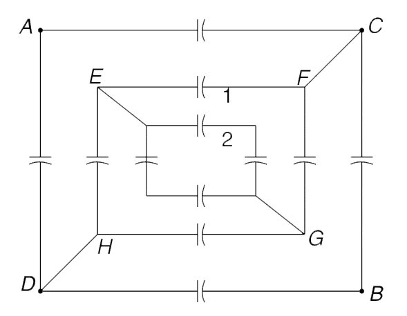
View SolutionIn the circuit shown in the figure all the capacitors have capacitance C.
(a) Find the charge on capacitors marked as 1 and 2 when a battery of emf V is connected across points A and B.
(b) Find the equivalent capacitance across points C and D marked in the Figure.
(c) Find the equivalent capacitance across points E and G.
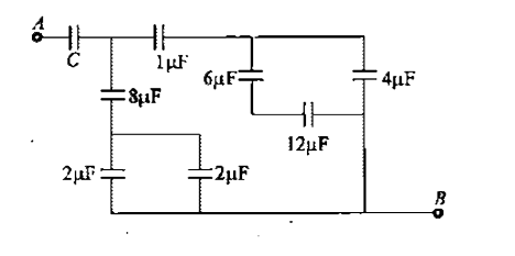
View SolutionFind the capacitance C in the circuit shown in figure if the equivalent capacitance between points A and B is 1μF.
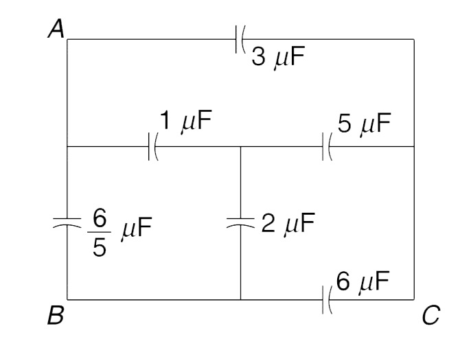
View SolutionIn the circuit shown in the Figure find the ratio of equivalent capacitance between A and B to that between A and C.
View SolutionA network of four capacitors each of 15μF four capacitors each of the μF capacitance is connected to a 500 V supply as shown in the figure . Determine (a) equivalent capacitance of the network and (b) charge on each capacitor .
View Solution
