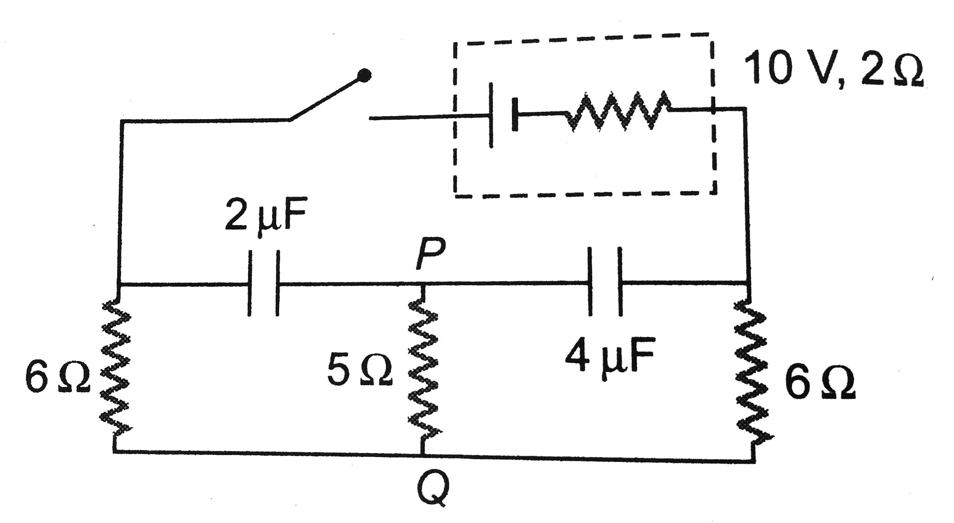
In the circuit shown in figure, the capacitors are initially uncharged. The current through resistor PQ just after closing the switch is
2A from P to Q
2A from Q to P
6A from P to Q
zero
The correct Answer is:D
At t=0 when capacitors are initially uncharged, their equivalent resistance is zero. Hence, whole current passes throug these capacitors.
Topper's Solved these Questions
- BOOK - DC PANDEYCHAPTER - CAPACITORSEXERCISE - OBJECTIVE_TYPE1videos
CAPACITORS
- BOOK - DC PANDEYCHAPTER - CAPACITORSEXERCISE - OBJECTIVE_TYPE1videos
CAPACITORS
- BOOK - DC PANDEYCHAPTER - ATOMSEXERCISE - MEDICAL ENTRANCES GALLERY42videos
ATOMS
- BOOK - DC PANDEYCHAPTER - COMMUNICATION SYSTEMEXERCISE - Subjective11videos
COMMUNICATION SYSTEM
Similar Questions
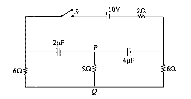
In the circuit shown in figure-3.351 the capacitors are initially uncharged. The current through resistor PQ just after closing the switch is :
 View Solution
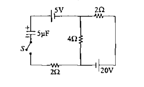
In the circuit shown in figure 3.242 capacitor is charged with 50μC charge. Find the current in 4Ω resistance just after switch S is closed.
 View Solution
Knowledge Check
- Question 1 - Select One
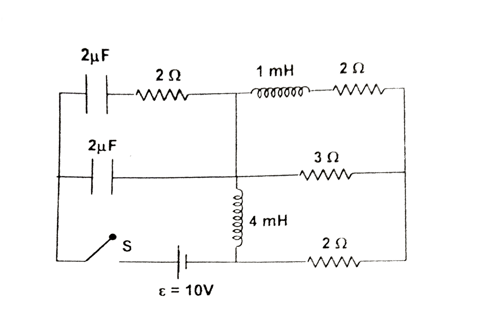
In the circuit shown, all the capacitors are initially uncharged. The current through the battery just after closing the switch 'S' isA2AB4AC5AD10A - Question 2 - Select One or More
In the circuit shown key is closed at t=0 with capacitor initially uncharged.
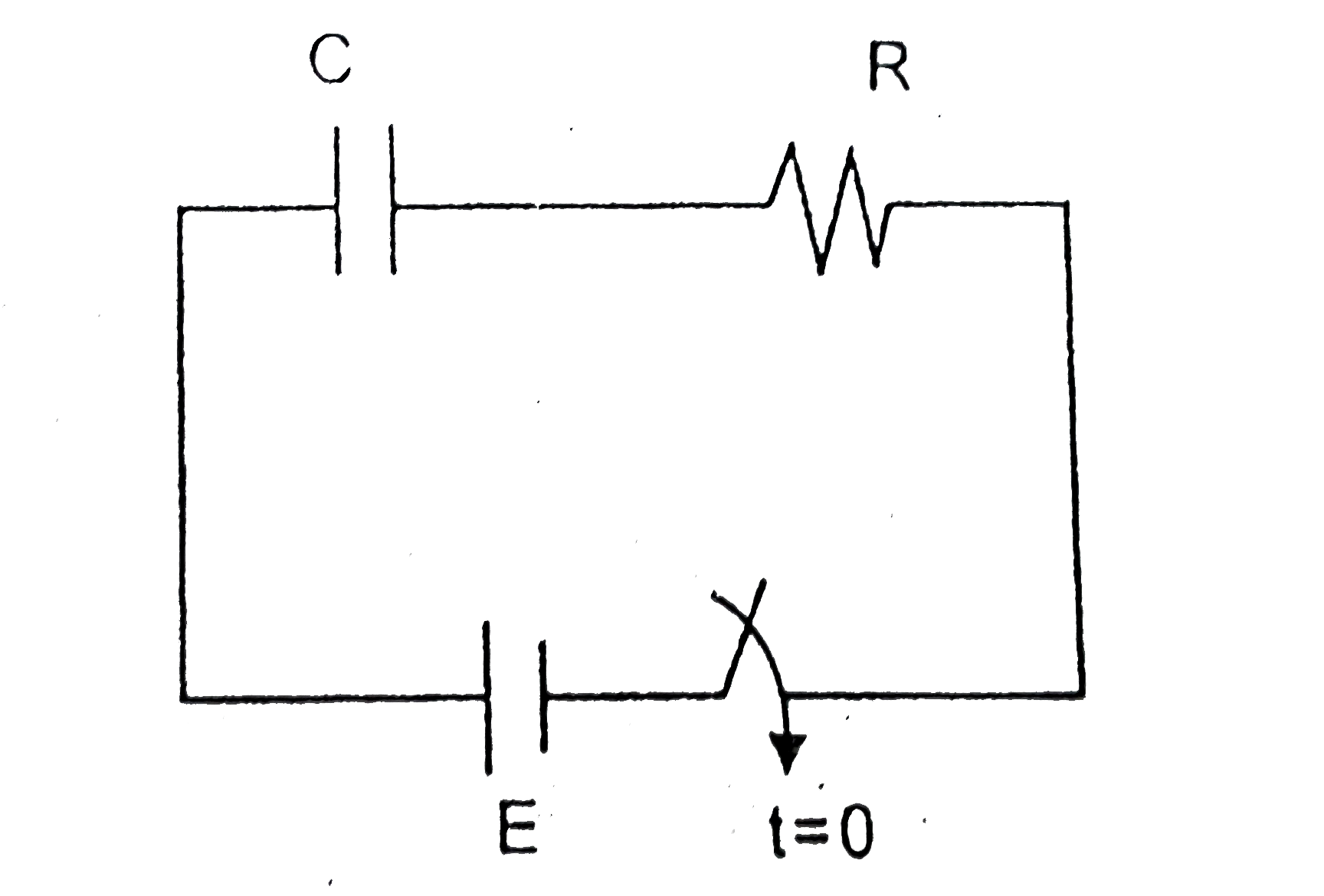 ARate of increase of capacitors energy, just after the switch is closed is E2RBMaximum power supplied by the cell is E2RCAt t=RCIn2, capacitor is charged up to half of the energy stored by it in steady stateDAt t=RCIn2, potential difference across capacitor is same that across resistor.
 - Question 3 - Select One
In the circuit shown in figure-3.348 when the switch is closed, the initial current through the 1Ω resistor just after closing the switch is
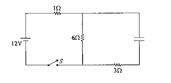 A2AB4AC3AD6A
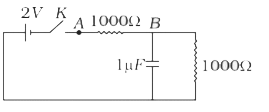
In the adjoining circuit, the capacitor is initially uncharged. The current through the resistor AB immediately after the key K is pressed is __________ mA.
 View Solution
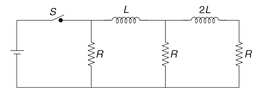
In the circuit shown in figure, the current through each resistor is I. Find the currents through the resistors immediately after the switch ‘S’ is opened. How much heat will get dissipated in the circuit after thw switch is opened ?
 View Solution
The circuit consists of two resistors (of resistance R1=20Ω and R2=10Ω), a capacitor (of capacitance C=10μF) and two ideal cells. In the circuit shown the capacitor is in steady state and the switch S is open
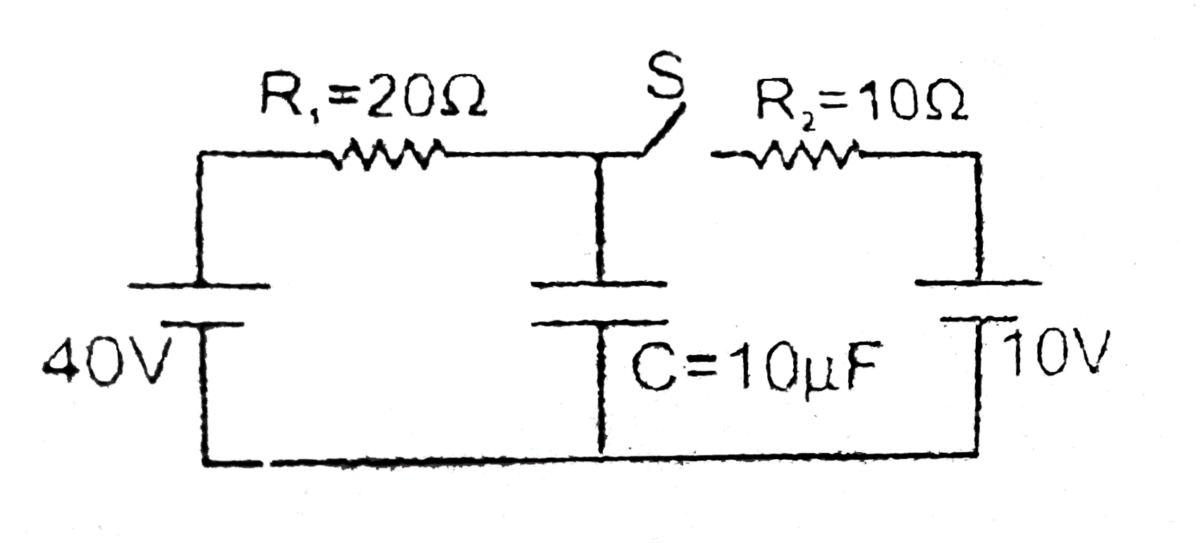
The current through the resistor R2 just after the switch S is closed is :View SolutionIn the circuit shown, the switch 'S' is closed at t=0. Then capacitor is initially uncharged. Then the current through the resistor R=8Ω at t=0.4×10⁻³sec is (Take e−2=0.135 )
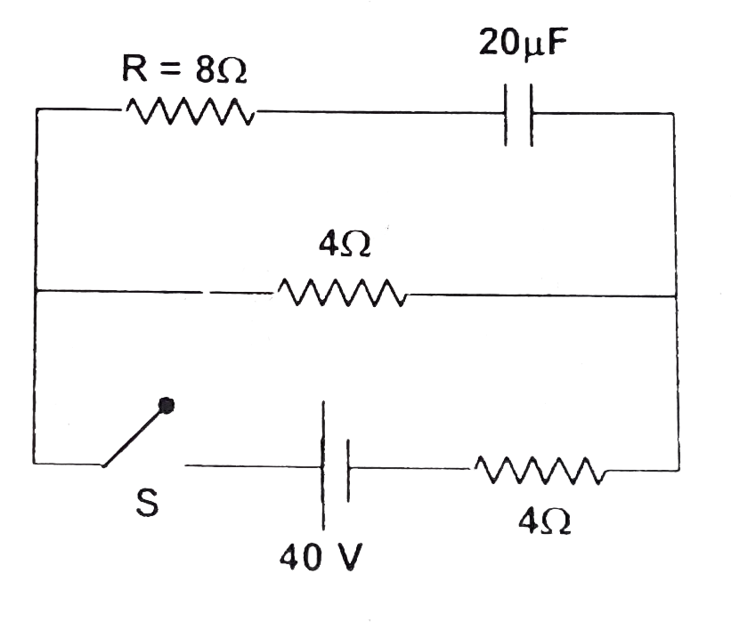 View Solution
In the circuit shown in the figure, the capacitor C is charged to a potential Vo. The heat generated in the circuit when the switch S is closed, is
View Solution

