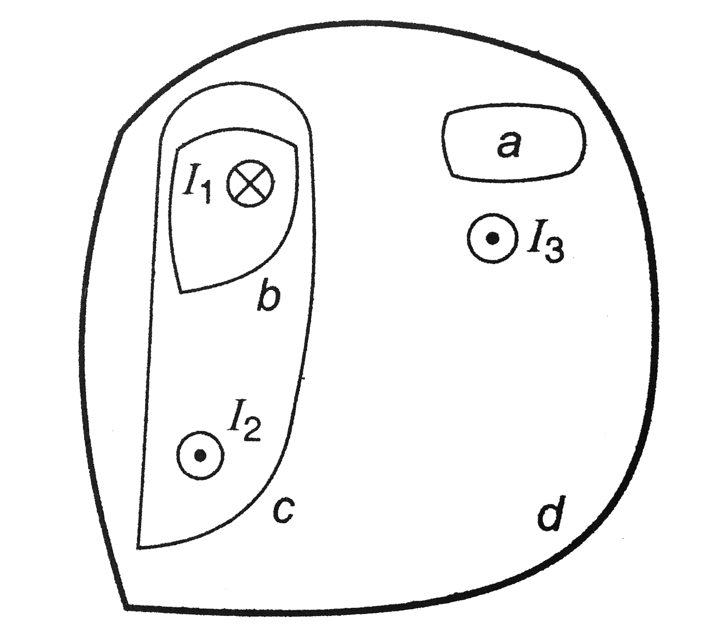
Figure shows, in cross-section, several conductors that carry currents through the plane of the figure. The currents have the magnitudes i1=4.0A,I2=6.0A, and I3=2.0 A, in the directions shown. Four paths labelled a to d, are shown. What is the line integral ∫B.dI for each path? Each integral involves going around the path in the counter-clockwise direction.
∫B.I=μ(inet)
Along path as net current enclosed by this path is zer.
Hence line integral =0
along path b inetis(ox). So, magnetic lines along this current is clockwise. But, we have to take line integral in counter clockwise direction. Hence, line integral will be negative.
Topper's Solved these Questions
- BOOK - DC PANDEYCHAPTER - MAGNETICSEXERCISE - INTRODUCTORY EXERCISE1videos
MAGNETICS
- BOOK - DC PANDEYCHAPTER - MAGNETICSEXERCISE - SUBJECTIVE_TYPE1videos
MAGNETICS
- BOOK - DC PANDEYCHAPTER - MAGNETICSEXERCISE - MCQ_TYPE1videos
MAGNETICS
- BOOK - DC PANDEYCHAPTER - MAGNETIC FIELD AND FORCESEXERCISE - Medical entrance s gallery59videos
MAGNETIC FIELD AND FORCES
- BOOK - DC PANDEYCHAPTER - MAGNETISM AND MATTEREXERCISE - Medical gallery1videos
MAGNETISM AND MATTER
Similar Questions
Four long wires each carrying current I as shown in the figure are placed at the points A, B, C and D. Find the magnitude and direction of
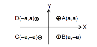
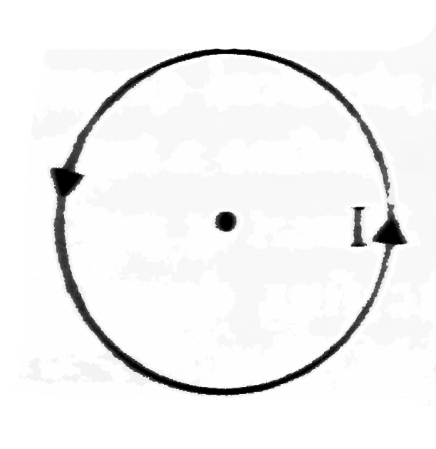
magnetic field at the centre of the square.View SolutionIn figure is shown a circular loop carrying current I. Show the direction of the magnetic field with the help of lines of force.
 View Solution
Knowledge Check
- Question 1 - Select One
In the given circuit diagram, the currents, I1=−0.3A,I4=0.8A and I5=0.4A, are flowing as shown. The currents I2,I3 and I6 respectively, are :
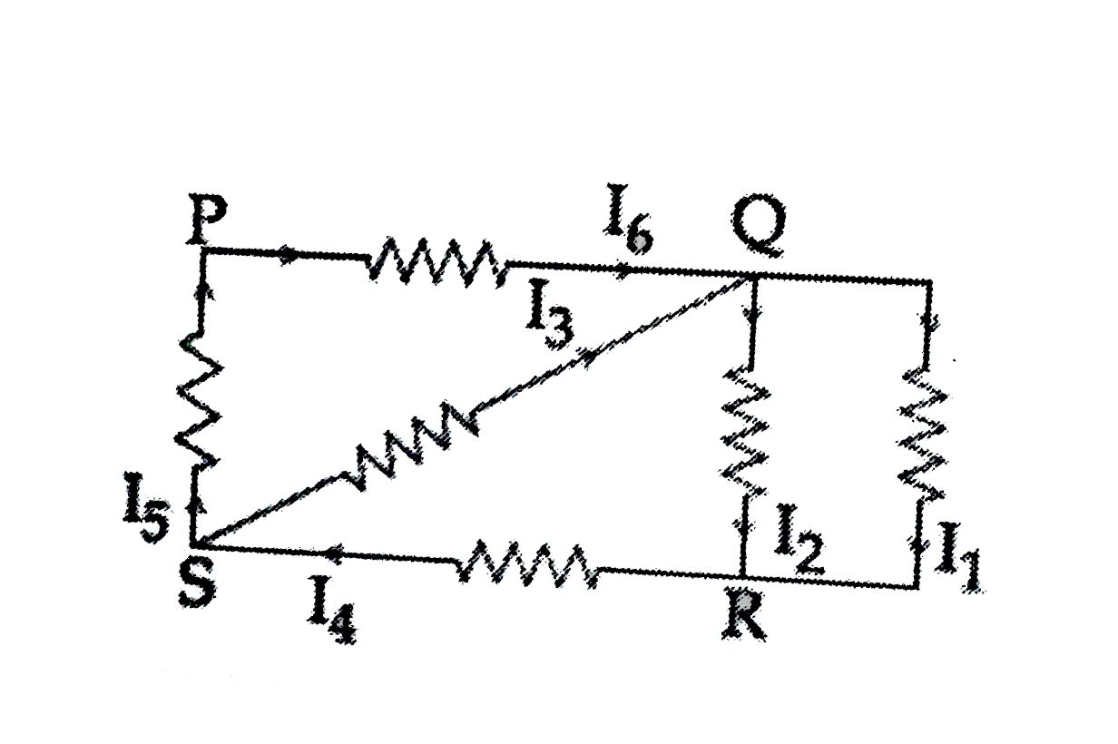 A1.1A,−0.4A,0.4AB1.1A,0.4A,0.4AC0.4A,1.1A,0.4AD−0.4A,0.4A,1.1A
 - Question 2 - Select One
In the given circuit diagram, the currents, I1=−0.3A,I4=0.8A and I5=0.4A, are flowing as shown. The currents I2,I3 and I6 respectively, are :
 A1.1A,−0.4A,0.4AB1.1A,0.4A,0.4AC0.4A,1.1A,0.4AD−0.4A,0.4A,1.1A
 - Question 3 - Select One
Figure. Shows two long wires carrying equal currents I1andI2 flowing in opposite directions. Which of the arrows labeled A to D correctely represents the direction of the magnetic field due to the wires at a point located at an equal distance d from each wire?
AABBCCDD
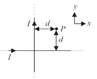
Two very long, straight, and insulated wires are kept at 90∘ angle from each other in xy-plane as shown in the figure. These wires carry currents of equal magnitude I, whose directions are shown in the figure. The net magnetic field at point will be:
 View Solution
Each of the eight conductors in the below figure carries 2.0 A of current into or out of the page . Two paths are indicated for the line integal ∮→B.d→s. What is the value of the integal for (a) path 1 and (b) path 2 ?
 View Solution
A closed cure encircles several conductors. The line integral ∫B.dI around this curve is 3.83×10⁻⁷T−m
a. What is the net current in the conductors?
b. If you were to integrate aroundthe curve in the opposite direction, what would be the value of the line integral?View SolutionFigure shows an end view of two long, parallel wires perpendicular to the xy plane, each carrying a current I, but in opposite directions.
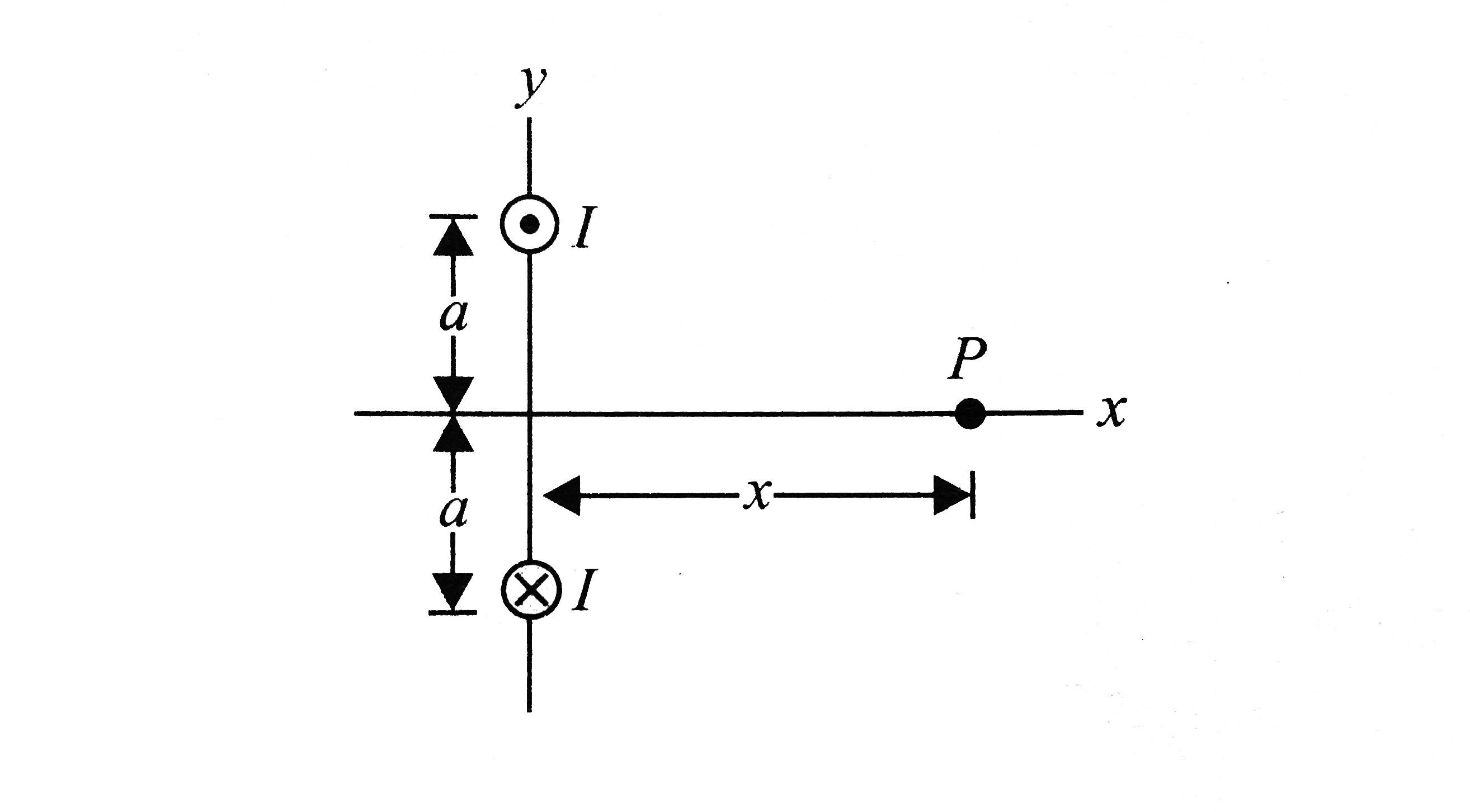
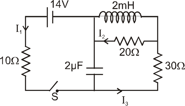
Graph the magnitude of →B at point on the x-axis.View SolutionIn the circuit shown, the switch is closed at t=0, the currents I1,I2 and I3 are
 View Solution
