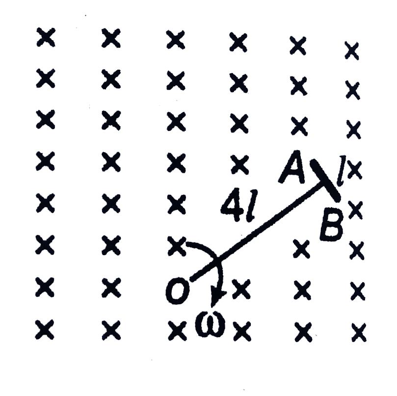
In the figure shown a T-shaped conductor moves with constant angular velocity ω in a plane perpendicular to uniform magnetic field B. The potential difference VA−VB is

zero
12Bωl2
2Bωl2
Bωl2
The correct Answer is:A
In AB,I is parallel to its v. Hence PD=0
Topper's Solved these Questions
- BOOK - DC PANDEYCHAPTER - ELECTROMAGNETIC INDUCTIONEXERCISE - Objective Questions3videos
ELECTROMAGNETIC INDUCTION
- BOOK - DC PANDEYCHAPTER - ELECTROMAGNETIC INDUCTIONEXERCISE - Level 1 Subjective21videos
ELECTROMAGNETIC INDUCTION
- BOOK - DC PANDEYCHAPTER - ELECTROMAGNETIC INDUCTIONEXERCISE - Level 1 Assertion And Reason10videos
ELECTROMAGNETIC INDUCTION
- BOOK - DC PANDEYCHAPTER - CURRENT ELECTRICITYEXERCISE - Medical entrances gallery97videos
CURRENT ELECTRICITY
- BOOK - DC PANDEYCHAPTER - ELECTROMAGNETIC WAVESEXERCISE - Sec C22videos
ELECTROMAGNETIC WAVES
Similar Questions
A conductor of length T'is rotated about one of its ends at a constant angular speed 'ω' in a plane perpendicular to a uniform magnetic field B. Plot graphs to show variations of the emf induced across the ends of the conductor with (i) angular speed o and (ii) length of the conductor i.
View SolutionA conductor is moving with velocity v in a region of uniform magnetic field B.The electric field at P inside conductor is
View Solution
Knowledge Check
- Question 1 - Select One
A metal rod of length 2m is rotating with an angular velocity of 100rad/sec in a plane perpendicular to a uniform magnetic field of 0.3T. The potential difference between the ends of the rod is
A30VB40VC60VD600V - Question 2 - Select One
A conducting rod of length l is falling with a velocity v perpendicular to a uniform horizontal magnetic field B. The potential difference between the two ends will be
A2 BlvBBlvC12BlvD12Bl2v2 - Question 3 - Select One
A conducing rod of length l is falling with a velocity v perpendicular to a unifrorm horizontal magnetic field B . The potential difference between its two ends will be
A2BlvBBlvC0.5BlvDB2l2v2
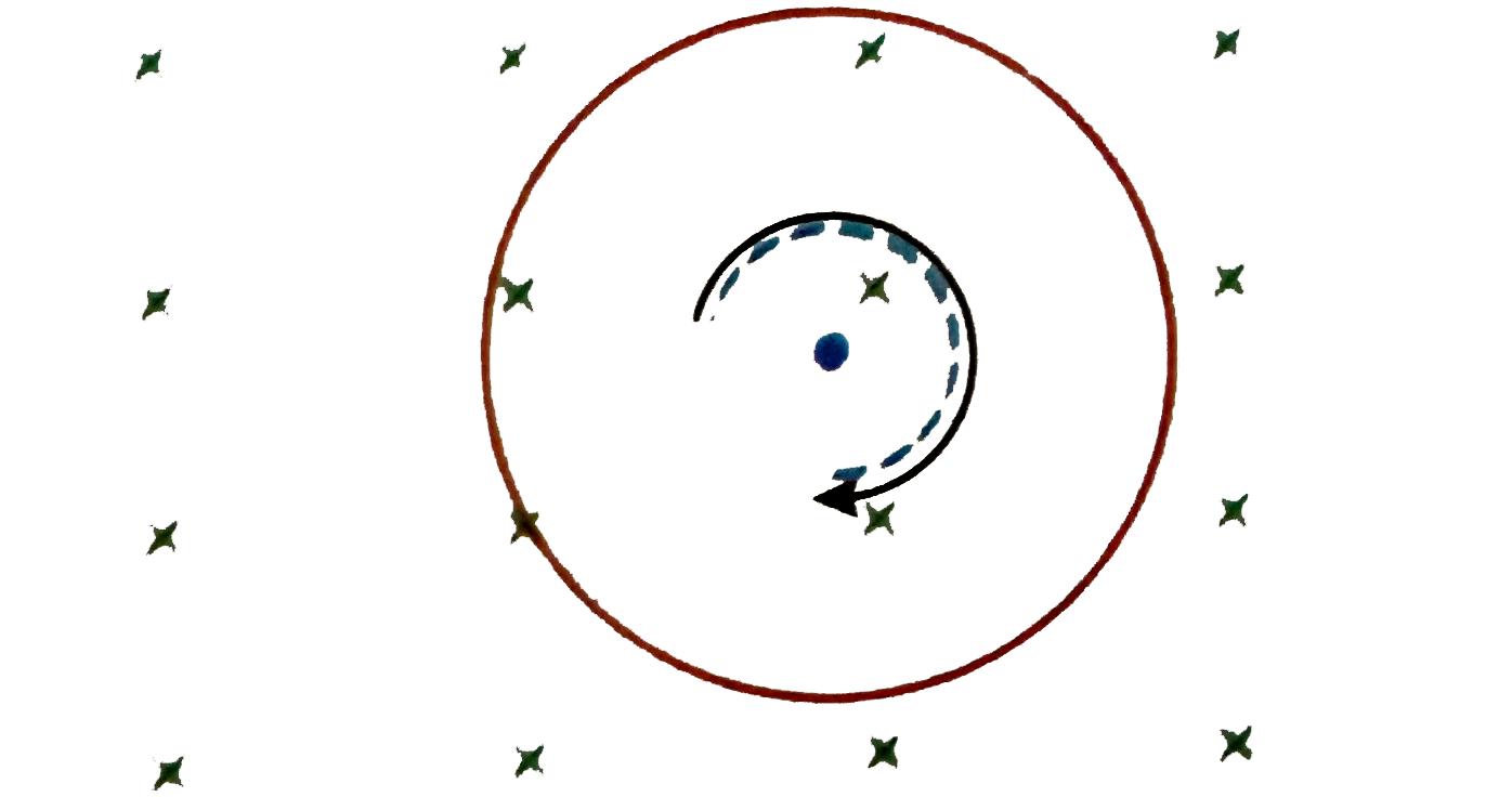
A non-conducting disk of radius R is rotating about its own axis with constant angular velocity ω in a perpendicular uniform magnetic field B as shown in figure. The emf induced between centre and rim of disk is
 View Solution
A conducting wheel in which there are four rods of lengthe l as shown in figure is rotating with angular velocity ω in a uniform magnetic field B. The induced potential difference between its centre and rim will be
 View Solution
A circular metal plate of radius R is rotating with a uniform angular velocity ω with its plane perpendicular to a uniform magnetic field B. Then the emf developed between the centre and the rim of the plate is :
View SolutionA circular metal plate of radius R is rotating with a uniform angular velocity ω with its plane perpendicular to a uniform magnetic field B. Then the emf developed between the centre and the rim of the plate is :
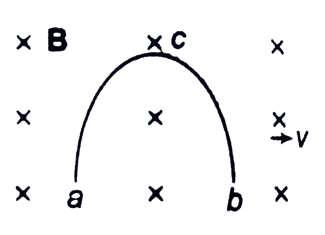
View SolutionA semi circular conducting ring acb of radius R moves with constant speed v in a plane perpendicular to uniform magnetic field B as shown in figure.

Identify the correct statement.View Solution

